background image

2.7  Setting the 0% and 100% Values

Procedure

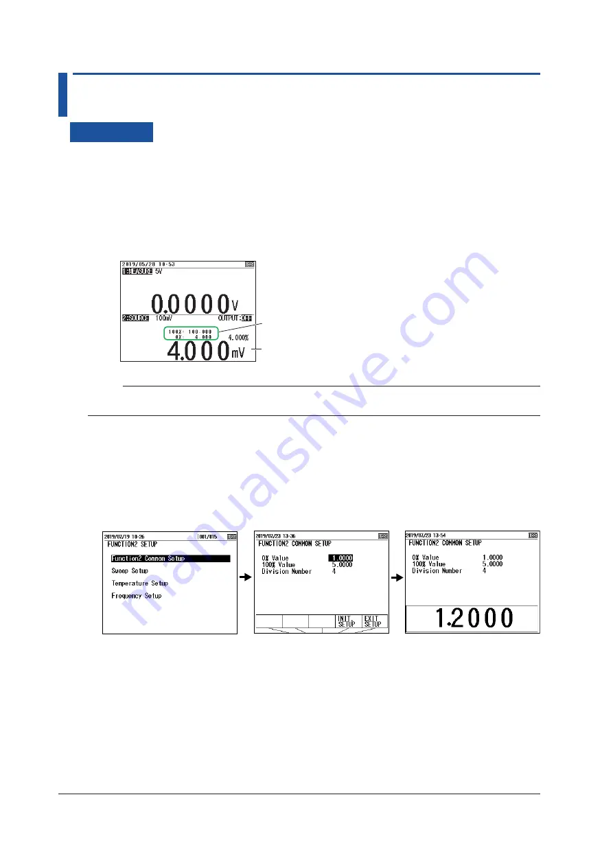
Setting Values Using the 0% and 100% Keys

1.

  With the source value and measurement value displayed, use the arrow keys to set the 0% 

source value.

2.

  Hold down the 

0%

 cursor key. The specified source value is assigned to the 0% value.

3.

  Use the arrow keys to set the 100% source value.

4.

  Hold down the 

100%

 cursor key. The specified source value is assigned to the 100% value.


When you hold down the 0% or 100% key, 

this value is assigned to 0% or 100%.

When you display the percentage value, 

you can check the 0% or 100% values.

Note

If you display the percentage on the screen using the DISPLAY key, you can view the assigned 0% and 

100% values.

Setting Values Using the Setup Menu

1.

  With the source value and measurement value displayed, press 

SETUP

 under Function 2.

2.

  Use the arrow keys to select 

Function2 Common Setup

, and then press 

ENTER

.

3.

  Use the arrow keys to select the 

0% Value

 value, and then press 

ENTER

. The settings are 

displayed at the bottom of the screen.

4.

  Use the arrow keys to set the 0% value, and then press 

ENTER

.

5.

  Likewise, set the 100% value.

6.

  Press the arrow key corresponding to 

EXIT SETUP

. The settings are confirmed, and a screen 

appears showing the source value and measurement value.


The cancel the settings, press 

ESC

 to return to the screen in step 2.


To initialize the settings, press the arrow key corresponding to 

INIT SETUP

.

2-16

IM CA500-01EN

Summary of Contents for CA500

Page 1: ...User s Manual CA500 CA550 Multifunction Process Calibrator IM CA500 01EN 1st Edition...

Page 2: ...he following sheet Document No Description PIM 113 01Z2 List of worldwide contacts Notes The contents of this manual are subject to change without prior notice as a result of continuing improvements t...

Page 3: ...ii IM CA500 01EN Revisions October 2019 1st Edition...

Page 4: ...he instrument This symbol appears on the instrument to indicate that the user must refer to the user s manual for special instructions The same symbol appears in the corresponding place in the user s...

Page 5: ...ys to select 20 ON and OFF appear in the selection menu 4 Use the arrow keys to select ON or OFF Confirming the Settings 5 Press the arrow key corresponding to EXIT SETUP The settings are confirmed an...

Page 6: ...Frequency and Pulse Source 2 12 2 7 Setting the 0 and 100 Values 2 16 2 8 Dividing and Generating the Source Values 2 18 2 9 Sweep Source 2 20 Chapter 3 Measurement 3 1 DC Voltage Measurement 3 1 3 2...

Page 7: ...er Supply 6 4 6 4 Setting the Decimal Symbol and CSV Separator 6 5 6 5 Setting the Date Display Format 6 6 6 6 Setting the Language 6 7 6 7 Formatting Initializing the Internal Memory 6 8 Chapter 7 US...

Page 8: ...arately RJ sensor sold separately DC voltage DC current resistance TC RTD pulse Block Diagram CPU CPU DC DC DC DC CPU TC A H L H L LOOP mA FUNCTION 2 part DC DC ADC Power Source Communication Port ADC...

Page 9: ...uare root operation 5 V 6 0000 V Maximum output current 10 mA 30 V 33 000 V Maximum output current 1 mA 1 5 V Range The interval between 0 and 100 is equally divided by four and the 0 25 50 75 and 100...

Page 10: ...mA 16 mA and 20 mA in 4 mA steps by pressing the UP or DOWN key This is convenient when calibrating the five points from 4 to 20 mA Square Root Output Function 4 20 mA Values corresponding to the squa...

Page 11: ...he device to be calibrated such as a resistance measuring instrument and RTD thermometer Therefore this instrument can be used only for instruments that measure pseudo resistance using a current for m...

Page 12: ...90 and IPTS 68 Connection Terminals This instrument is equipped with the following two types of terminals TC A TC mini plug A thermocouple is connected to the instrument using a thermocouple mini plug...

Page 13: ...200 0 C GOST R 8 625 2006 Cu100M 180 0 C to 200 0 C GOST R 8 625 2006 Complies also with JIS C 1604 Frequency Pulse signals are generated at the following frequencies Range Source Range Notes 500 Hz...

Page 14: ...or 4 20mA Simulate the number divisions is fixed to 4 Display Switching You can select the value to show on the main display of the function 2 display area between a physical value such as a voltage o...

Page 15: ...rom 100 to 0 sweep down 100 0 Output on Sweep start UP key Interval time 100 0 Output on Sweep start DOWN key Interval time Time Source value Time Source value Sweep time rise time Sweep time fall tim...

Page 16: ...ep start UP key Repetition Off Repetition On Output off OUTPUT key Time Source value Time Source value Interval time Operation While Sweeping Is in Progress If you press UP or DOWN while sweeping is i...

Page 17: ...variation of each step is given by Variation 100 source value 0 source value number of divisions Given 0 source value 1 V 100 source value 5 V number of divisions 4 5 V 1 V 4 1 V The source value is...

Page 18: ...s to each number from 1 to 10 on the CA500 and 1 to 20 on the CA550 When the output is turned on the specified source values are generated in order from source number 1 The source time of each source...

Page 19: ...oltage This function measures the following DC voltages Range Measurement Range Notes 100 mV 110 000 mV Input resistance 1 G or more 5 V 6 0000 V Input resistance Approx 1 M 50 V 55 000 V Input resist...

Page 20: ...ance of measurement lead cables and contact resistance Use this when you want to make accurate measurements Temperature Measurement Using Thermocouples Temperature is measured using the following ther...

Page 21: ...1 JPT100 PT100 3916 200 0 C to 510 0 C JIS C 1604 1989 JPt100 PT100 3850 200 0 C to 630 0 C JIS C 1604 1989 Pt100 PT100 3926 200 0 C to 630 0 C Minco Application Aid 18 PT200 200 0 C to 630 0 C IEC 60...

Page 22: ...to the specifications of the device to be calibrated to the 0 or 100 source value of this instrument you can determine the output value of the device to be calibrated for the source value For example...

Page 23: ...perature can also be shown Function Main display Sub display 1 Sub display 2 Sub display 3 DC voltage Measured value Percentage Percentage Measured value DC Current Measured value Percentage Percentag...

Page 24: ...get model number serial number and tag number The assigned information can be saved as CSV data along with source values measured values and errors Because measured values source values errors pass fa...

Page 25: ...value when the SAVE key is pressed are saved Auto Save in Step Sweeps or Program Sweeps The date and time information such as the specified function and range the source value and measured value of e...

Page 26: ...standard setting IPTS 68 ITS 90 Temperature unit C Frequency setting Amplitude voltage setting Pulse count setting TC measurement settings 0 value 100 value Contact output setting ON OFF Not saved wh...

Page 27: ...ng is changed on the Device Setup screen When the function or range is changed When the number of save data points exceeds 2000 When the power is turned off Auto Save in Step Sweeps Information such a...

Page 28: ...ATE FORMAT 0 YYYY MM DD 1 DD MM YYYY 2 MM DD YYYY Range Measurement range source range 0 VALUE 100 VALUE CONTACT contact I O 0 OFF 1 ON TC SETTING temperature setting Thermocouple terminal setting 0 T...

Page 29: ...urement range source range 0 VALUE 100 VALUE DIVISION NUMBER number of divisions CONTACT contact I O 0 OFF 1 ON TC SETTING temperature setting Thermocouple terminal setting 0 TC A 1 TC B TC B RJC sett...

Page 30: ...90 1 IPTS 68 Temperature unit 0 C FREQUENCY SETTING frequency setting Amplitude voltage setting Pulse count setting MODEL NO Model number TAG NO Tag number SERIAL NO Serial number CALIBRATION DATE Ca...

Page 31: ...to power off is automatically disabled the icon also disappears in the following situations Pulse count is in progress The output is on Sweeping is in progress Power is being supplied through USB Turn...

Page 32: ...per left of the screen the date and time on the LOAD screen and the date and time saved in CSV files from the CA550 Language You can select the language used on the screen from the following English J...

Page 33: ...Source Value 5 With the source value and measurement value displayed use the arrow keys to set the source value Source value Source range When the source range is 1 5V or 1 5V pressing UP or DOWN cha...

Page 34: ...can be used as a calibration signal for instruments that output the square root of input signals Values for square root operation are generated Source Value Voltages within each source range are gener...

Page 35: ...ue and measurement value displayed use the arrow keys to set the source value Source value Source range When the source range is 4 20mA 4 20mA or 4 20mA Simulate pressing UP or DOWN changes the source...

Page 36: ...mA are generated 4 20 mA Simulate Currents ranging from 0 to 20 mA that simulate transfer signals are generated This can be used to perform a loop check on the source value by connecting to a distribu...

Page 37: ...e The display returns to the source and measurement value display Setting the Source Value 5 With the source value and measurement value displayed use the arrow keys to set the source value Source val...

Page 38: ...0 01EN Description Source Range You can select from the following two source ranges Range Source Range 400 0 00 440 00 4000 0 0 4400 0 Note If the allowable measurement current exceeds the upper limit...

Page 39: ...to the source and measurement value display Setting the Source Value 5 With the source value and measurement value displayed use the arrow keys to set the source value Source value Reference junction...

Page 40: ...ection menu 13 Use the arrow keys to set the temperature scale Confirming the Settings 14 Press the arrow key corresponding to EXIT SETUP The settings are confirmed and a screen appears showing the so...

Page 41: ...C On and Off When using the TC B terminal set whether to perform RJC ON OFF ON If an external RJ sensor is connected the external RJ sensor is used to perform reference junction compensation If an ext...

Page 42: ...the RTD type The display returns to the source and measurement value display Setting the Source Value 5 With the source value and measurement value displayed use the arrow keys to set the source valu...

Page 43: ...PT500 200 0 C to 630 0 C PT1000 200 0 C to 630 0 C Cu10 100 0 C to 260 0 C Ni120 80 0 C to 260 0 C PT50 200 0 C to 630 0 C PT50G 200 0 C to 800 0 C PT100G 200 0 C to 630 0 C Cu50M 180 0 C to 200 0 C C...

Page 44: ...ULSE The display returns to the source and measurement value display Setting the Source Range 3 Under Function 2 press RANGE 4 Use the arrow keys to set the source range The display returns to the sou...

Page 45: ...ENTER If you set the number to 0 Continue will be selected Setting the Amplitude and the Number of Pulses 12 Press the arrow key corresponding to EXIT SETUP The settings are confirmed and the screen...

Page 46: ...tialize the settings pressing the arrow key corresponding to INIT SETUP Turning the Source On and Off 18 With the source value and measurement value displayed press OUTPUT ON OFF The source value set...

Page 47: ...ignals that this instrument generates is 50 Pulse Count Set the number of pulses to generate If you set the number to 0 the instrument continuously generates pulse signals at the specify frequency Con...

Page 48: ...creen using the DISPLAY key you can view the assigned 0 and 100 values Setting Values Using the Setup Menu 1 With the source value and measurement value displayed press SETUP under Function 2 2 Use th...

Page 49: ...OUTPUT ON OFF OUTPUT OFF on the screen changes to OUTPUT ON and are displayed 0 or 100 value is generated To turn off the source press OUTPUT ON OFF again Description 0 and 100 Values Set the values...

Page 50: ...to 4 5 Press the arrow key corresponding to EXIT SETUP The settings are confirmed and a screen appears showing the source value and measurement value The cancel the settings press ESC to return to th...

Page 51: ...DOWN key DOWN key 0 20 40 60 80 UP key DOWN key 100 The number divisions can be set in the range of 1 to 20 When the source range is 1 5V 1 5V 4 20mA 4 20mA or 4 20mA Simulate the number divisions is...

Page 52: ...w keys to set the rise time or fall time and press ENTER Setting the Interval Time 6 Select Interval Time and press ENTER The settings are displayed at the bottom of the screen 7 Use the arrow keys to...

Page 53: ...ON OFF to turn off the source If repeat is set to ON sweeping continues until you turn off the source Setting and Executing Step Sweeps 3 Select Step Sweep Setup and press ENTER Set the interval time...

Page 54: ...nding to INIT SETUP Executing a Step Sweep 11 With the source value and measurement value displayed press SWEEP under Function 2 several times to display STEP SWEEP on the screen The source value disp...

Page 55: ...hen the sweep is completed Setting the Source Value 8 Use the cursor keys to display page 2 2 of Program Sweep Setup 9 Select No 1 under Output Data ON and OFF appear 10 Use the arrow keys to select O...

Page 56: ...rce value and measurement value displayed press SWEEP under Function 2 several times to display PROGRAM SWEEP on the screen The source value display is set to the value assigned to source value No 1 P...

Page 57: ...appear in the selection menu 7 Use the arrow keys to set data save to ON or OFF When you set this to on the measurement values and source values are saved automatically when the sweep is completed Set...

Page 58: ...tings 16 Press the arrow key corresponding to EXIT SETUP The settings are confirmed and a screen appears showing the source value and measurement value The cancel the settings press ESC to return to t...

Page 59: ...rce voltage or current is the square root of each percentage Rise Time and Fall Time These are the times during which the source value is varied from 0 to 100 or from 100 to 0 You can specify 5 to 600...

Page 60: ...Time The time period during which the source value of each step is held You can specify 5 to 600 s Repeat The interval for the signal to rise and fall or to fall and rise is considered a cycle Set whe...

Page 61: ...source values in percentages If not all source values are assigned and there is a source number set off or a unused source number the instrument sweeps up to the number that a source value is assigne...

Page 62: ...any of the following keys while sweeping stops the sweeping FUNCTION2 RANGE2 ESC or OUTPUT Pressing any other keys except the power key does not affect the sweeping operation Some keys are disabled du...

Page 63: ...n options are displayed 2 Use the arrow keys to select V The display returns to the source and measurement value display Set the measuring range 3 Under Function 1 press RANGE 4 Use the arrow keys to...

Page 64: ...V 6 0000 V 50 V 55 000 V 0 Value and 100 Value Assign an output value specified according to the specifications of the device to be calibrated to the 0 or 100 measurement value of this instrument whic...

Page 65: ...nt value display Set the measuring range 3 Under Function 1 press RANGE 4 Use the arrow keys to set the measurement range The display returns to the source and measurement value display Setting the 0...

Page 66: ...asurement Range 50 mA 60 000 mA Loop Power Loop power can be generated during DC current measurement Transfer signals can be measured while supplying a constant voltage of 24 VDC to the two wire trans...

Page 67: ...isplay Setting the 0 and 100 Values when necessary 5 Set the 0 and 100 values according to section 3 7 Setting the 0 and 100 Values Setting the Wiring System 6 With the source value and measurement va...

Page 68: ...can select from the following two measurement ranges Range Measurement Range 400 0 00 440 00 4000 0 0 4400 0 Wiring Systems You can select from 2W two wire 3W three wire and 4W four wire This setting...

Page 69: ...ys to set the TC type The display returns to the source and measurement value display Setting the 0 and 100 Values when necessary 5 Set the 0 and 100 values according to section 3 7 Setting the 0 and...

Page 70: ...ettings 16 Press the arrow key corresponding to EXIT SETUP The settings are confirmed and the screen reverts to show the source value and measurement value The cancel the settings press ESC to return...

Page 71: ...o perform reference junction compensation Note The internal RJ sensor measures the temperature of the instrument s terminal When the temperature inside the instrument is high wait for the temperature...

Page 72: ...y Setting the 0 and 100 Values when necessary 5 Set the 0 and 100 values according to section 3 7 Setting the 0 and 100 Values Setting the Wiring System 6 With the source value and measurement value d...

Page 73: ...C PT100 3926 200 0 C to 630 0 C PT200 200 0 C to 630 0 C PT500 200 0 C to 630 0 C PT1000 200 0 C to 630 0 C Cu10 100 0 C to 260 0 C Ni120 80 0 C to 260 0 C PT50 200 0 C to 630 0 C PT50G 200 0 C to 80...

Page 74: ...and 100 values according to section 3 7 Setting the 0 and 100 Values Setting the Contact Input and Setting the Count Time of the Pulse Count when the measurement range is set to PULSE COUNT 6 With the...

Page 75: ...tes 500 Hz 1 00 Hz to 550 00 Hz frequency measuring 5000 Hz 1 0 Hz to 5500 0 Hz frequency measuring 50 kHz 0 001 kHz to 50 000 kHz frequency measuring PULSE COUNT 0 to 99999 The number of pulses is co...

Page 76: ...1 To initialize the settings pressing the arrow key corresponding to INIT SETUP Temperature Measurements Using a Thermocouple 1 With the source value and measurement value displayed press SETUP under...

Page 77: ...thermocouple 0 and 100 values 0 and 100 values Measured value Measured value display of the measured value display of the measured value display of the measured value display of the measured value Mea...

Page 78: ...s to show the source value and measurement value The cancel the settings press ESC to return to the screen and step 1 To initialize the settings pressing the arrow key corresponding to INIT SETUP Desc...

Page 79: ...easurement value displayed press AVERAGE under Function 1 The average maximum and minimum values are displayed on the FUNCTION 1 screen Maximum Average Minimum Description Moving average values for ev...

Page 80: ...a field instrument check the output value at each calibration point Apply a signal to the device to be calibrated using the source function of this instrument and measure the output signal on this in...

Page 81: ...choice The display returns to the source and measurement value display 3 Under Function 2 press RANGE 4 Use the arrow keys to set the source range The display returns to the source and measurement va...

Page 82: ...ation target Set the serial number of the calibration target Output settings are on pages 2 3 and 3 3 4 Set the interval time data save and device information Set data save to on Setting the Source Va...

Page 83: ...ESC to return to the screen and step 1 To initialize the settings pressing the arrow key corresponding to INIT SETUP Description A field instrument is calibrated using the source function measurement...

Page 84: ...an set the data separator of CSV files to comma semicolon or tab When opening a CSV file in Excel or the like check the data separator setting that was used when the data was saved If the operating sy...

Page 85: ...entries can be saved including the saved sweep data Memory numbers from 001 to 100 are automatically assigned to the data entries Saving is not possible beyond 100 data entries Delete unneeded data S...

Page 86: ...to the same file until any of the following conditions is met When the FUNCTION1 SETUP or FUNCTION2 SETUP is changed When the function or range of Function 1 and Function 2 is changed When the number...

Page 87: ...0 YYYY MM DD 1 DD MM YYYY 2 MM DD YYYY Range Measurement range source range 0 VALUE 100 VALUE CONTACT contact I O 0 OFF 1 ON TC SETTING temperature setting Thermocouple terminal setting 0 TC A 1 TC B...

Page 88: ...ource values and measurement values of each step are saved automatically CA500 The saved information is the same as that explained in Saving Data Manually and Section 5 1 A total of up to 100 data ent...

Page 89: ...x csv YYYYMMDDhhmm year month day hour and minute when the data entry was saved xx A sequence number starting from 00 that is assigned when the save date and time overlaps Saved Information The follow...

Page 90: ...libration date YYYY MM DD CALIBRATOR S N CA550 serial number No Calibration point number DATE Calibration date YYYY MM DD TIME Calibration time of the calibration point hh mm ss MEASURE Measurement va...

Page 91: ...ect the data you want to load and then press ENTER The screen displays the loaded source value and measurement value LOAD appears at the top of the screen Function 1 data Function 2 data Memory number...

Page 92: ...cription You can load saved data to view measurement values and source values and change the settings according to the loaded data settings Data That Can Be Loaded The following data can be loaded CA5...

Page 93: ...mation displayed on the PC is not updated automatically To update the information remove the USB cable or restart the CA550 USB Interface Specifications Electrical and mechanical specifications Compli...

Page 94: ...xx xx xxx Function1 settings Function2 settings Measurement source value Data Saved Using Step Sweep MODEL CA550 FILE TYPE 2 CSV SEPARATOR 0 DECIMAL POIINT 1 DATE FORMAT 0 RANGE 4 20mA Type K 0 VALUE...

Page 95: ...TIME FUNCTION2 FUNCTION1 ERROR PASS FAIL 1 xxxx xx xx xx xx xx xxx xx xx xxx xxx xx PASS 2 xxxx xx xx xx xx xx xxx xx xx xxx xxx xx PASS 3 xxxx xx xx xx xx xx xxx xx xx xxx xxx xx PASS 4 xxxx xx xx x...

Page 96: ...keys to select ON or OFF To finish entering the settings here proceed to step 7 Turning the Light Timer On and Off 5 User cursor keys to select Light Timer ON and OFF appear in the selection menu 6 U...

Page 97: ...that automatically turns off the screen light when about 10 minutes elapses after the last user interaction with the instrument To turn the screen light on again press the key Turning the Light screen...

Page 98: ...nding to EXIT SETUP The settings are confirmed and a screen appears showing the source value and measurement value Pressing ESC causes the instrument to discard the settings and return to the menu scr...

Page 99: ...y power supply Confirming the Settings 5 Press the arrow key corresponding to EXIT SETUP The settings are confirmed and a screen appears showing the source value and measurement value Pressing ESC cau...

Page 100: ...entering the settings here proceed to step 8 CSV Separator 6 Use the cursor keys to select CSV Separator COMMA SEMI COLON and TAB appear on the selection menu 7 Use the cursor keys to set the symbol...

Page 101: ...rming the Settings 6 Press the arrow key corresponding to EXIT SETUP The settings are confirmed and a screen appears showing the source value and measurement value Pressing ESC causes the instrument t...

Page 102: ...ss ENTER A list of options appears 5 Use the cursor keys to select the language you want to use and press ENTER Confirming the Settings 6 Press the arrow key corresponding to EXIT SETUP The settings a...

Page 103: ...ved Data to a PC CA550 Procedure 1 With the source value and measurement value displayed press MENU 2 Use the cursor keys to select File Format and then press ENTER A File Format screen appears 3 Pres...

Page 104: ...50 This instrument complies with Mass Storage Class Ver1 x The data saved in the internal memory of this device can be loaded into a PC It is not possible to delete the data in this instrument or writ...

Page 105: ...PC If the operating system of the PC connected to this instrument is Windows 8 1 you need to install a CDC system definition file for YOKOGAWA products in the PC For details on how to obtain the syst...

Page 106: ...g to 0 of FUNCTION2 Yes No SP Sets or queries the pulse count operation state Yes No SSC Sets or queries the FUNCTION2 display Yes No TC Sets or queries the pulse count time Yes Yes TE Sets or queries...

Page 107: ...r queries the current DCA source SIMULATE Yes Yes MO Starts or stops or queries the measurement Yes Yes ND Sets or queries the n and m values of the n m divided output Yes Yes NM Sets or queries the n...

Page 108: ...nsmission command format Return Response data format of a command with a response queries IDN Queries the CA500 or CA550 ID string Command IDN CRLF Return YOKOGAWA CA5xx XXXXXXXXX a aa aaa Parameters...

Page 109: ...rn xxxxxxxxx CRLF Parameters xxxxxxxxx Serial number 9 digits BU Sets or queries the burnout on off state Command BUm CRLF Answer BUm CRLF Command BU CRLF Return BUm CRLF Parameters m 0 Burnout disabl...

Page 110: ...LF Parameters m 0 No headers default value 1 With headers HD Holds or queries the measurement value display Command HDm CRLF Answer HDm CRLF Command HD CRLF Return HDm CRLF Parameters m 0 Display upda...

Page 111: ...Answer MFm n CRLF Command MFm CRLF Return MFm n CRLF Parameters m 0 FUNCTION1 1 FUNCTION2 for TC n Function 0 DCV 1 DCA 2 3 TC 4 RTD 5 Freq 7 OFF When the parameter is omitted m 0 is assumed MH Sets o...

Page 112: ...n 0 400 500 on the CA150 1 4000 5 k on the CA150 TC n 0 K 1 E 2 J 3 T 4 R 5 B 6 S 7 N 8 L 9 U 10 C 11 XK 12 A 13 D 14 G 15 Platinel II 16 PR20 40 RTD n 0 PT100 1 JPT100 2 PT100 3850 3 PT100 3926 4 PT...

Page 113: ...rnout de 99999 E 3 For no data d the decimal place is according to the set range e E 0 E 3 E 3 E 6 If FUNCTION2 is set to TC measurement the response to OD CrLf or OD CrLf is a TC measurement value To...

Page 114: ...3 E 6 For over range or burnout de 99999 E 3 For no data d the decimal place is according to the set range e E 0 E 3 E 3 E 6 FUNCTION2 header section f V voltage A current O resistance T temperature F...

Page 115: ...LSE f source range DCV 100mV 1 5V 5V 30V DCA 20mA 4 20mA 20mA SIMULATE OHM 400OHM 4000OHM TC K E J T R B S N L U C XK A D G Platinel II PR20 40 RTD PT100 JPT100 PT100 3850 PT100 3916 PT200 PT500 PT100...

Page 116: ...0 J 210 0 to 1200 0 T 250 0 to 400 0 N 200 0 to 1300 0 L 200 0 to 900 0 U 200 0 to 600 0 R 20 0 to 1767 0 S 20 0 to 1768 0 B 600 0 to 1820 0 C 0 0 to 2315 0 XK 200 0 to 800 0 A 0 0 to 2500 0 D W3Re W2...

Page 117: ...resolution are the same as the display range of the selected source range SL Sets or queries the value corresponding to 0 of FUNCTION2 Command SLm CRLF Answer SLm CRLF Command SL CRLF Return SLm CRLF...

Page 118: ...e CA150 1 4000 5 k on the CA150 TC m 0 K 1 E 2 J 3 T 4 R 5 B 6 S 7 N 8 L 9 U 10 C 11 XK 12 A 13 D 14 G 15 Platinel II 16 PR20 40 RTD m 0 PT100 1 JPT100 2 PT100 3850 3 PT100 3926 4 R 5 B 6 S 7 N 8 L 9...

Page 119: ...value resistance 2 Room temperature ERR13 results when the function is not set to TC or RTD TS Executes manual saving Command TS CRLF Answer TS OK CRLF TT Sets or queries the international temperatur...

Page 120: ...ameters m 0 Stop loop power supply default value 1 Start loop power supply WC Sets or queries the wiring system of resistance measurement Command WCm CRLF Return WCm CRLF Command WC CRLF Return WCm CR...

Page 121: ...ction to OFF stop on the CA150 1 Sets the function and range to the settings before stopping start on the CA150 The above action is executed on the CA500 and CA550 ND Sets or queries the number divisi...

Page 122: ...ved a command that cannot be executed in the instrument s current condition Err 16 Detected an error during adjustment Err 20 24 VLOOP measurement power supply error Err 23 Detected an overvoltage or...

Page 123: ...e is read bit3 Set to 1 when a measurement over range occurs Cleared in the following situations When the status byte is read When the function is changed When the range is changed bit2 Set to 1 when...

Page 124: ...urement 1 18 3 5 resistance source 1 13 resistance source of an RTD 1 15 2 10 rise time 2 20 2 27 RJC 1 5 1 14 3 9 Numerics Page 0 100 value 1 7 1 15 2 16 3 14 1 5 V range 1 2 1 5 V range 1 2 4 20 mA...

Page 125: ...Tag Number 2 25 TC A 1 5 1 14 temperature measurement RTD 1 14 3 10 temperature measurement TC 1 13 3 7 temperature scale 1 5 2 9 3 9 terminal B 1 6 thermoelectromotive force source 1 25 2 7 three wir...

Reviews: