


3
IM AQ6370D-02EN
3
Panel Keys and Knobs
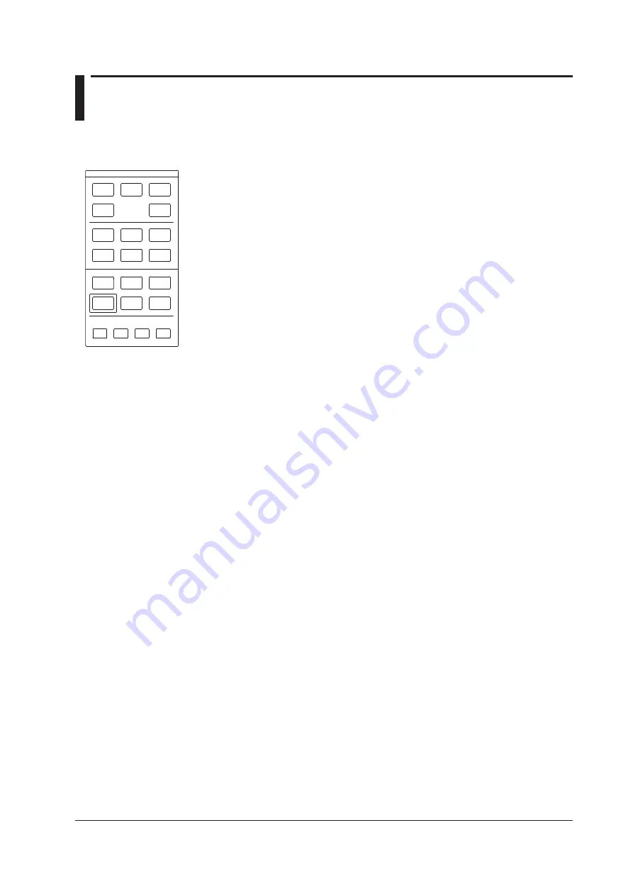
FUNCTION Section
The FUNCTION section contains 17 function keys and 4 auxiliary keys. When you press
a function key, information about the function is displayed on the soft key menu located
on the right side of the LCD display.
SWEEP
The SWEEP key contains functions related to sweeping. When you press the SWEEP
key, the soft key menu for sweeping appears.
CENTER
The CENTER key contains functions related to setting the center wavelength and center
frequency for measurements. The soft key functions change depending on whether the
screen display mode is wavelength display mode or frequency display mode.
SPAN
The SPAN key contains functions pertaining to settings for the wavelength span or
frequency span being measured. The soft key functions change according to whether the
screen display mode is wavelength display mode or frequency display mode.
LEVEL
The LEVEL key contains functions related to level axis settings.When you press the
LEVEL key, the soft key menu for setting reference level appears.
SETUP
The SETUP key contains functions related to measurement condition settings.
ZOOM
The ZOOM key contains the zoom function, which allows the user to freely enlarge or
reduce a measured waveform in order to check a small area of the measured waveform,
or to check the overall waveform.
This key is used to set the waveform enlarged/reduced display conditions.
DISPLAY
The DISPLAY key contains functions related to screen display.This key is used to set the
screen to upper/lower 2-split display mode (split mode).
TRACE
The TRACE key contains functions related to trace mode settings.
MARKER
The MARKER key contains functions related to markers.
PEAK SEARCH
The PEAK SEARCH key contains functions for searching for peaks and bottoms in
measured waveforms.
ANALYSIS
The ANALYSIS key contains functions related to measured waveform analysis.
FUNCTION
CENTER
SWEEP
SPAN
LEVEL
ZOOM
SETUP
MARKER
DISPLAY
PEAK
SEARCH
TRACE
ANALYSIS
USER
MEMORY
FILE
SYSTEM
ADVANCE
PROGRAM
OREMOTE
UNDO/
LOCAL
HELP
COPY
PRESET


