background image


<5.  Basic Operating Procedures>

51

IM 01E24A01-01EN

5.3  Display Mode and Setting 

Mode

The device runs in the Display Mode when the power 
is turned on.  For check or change of parameters, the 
Setting Mode must be activated. The following procesure 
explains how to change to the Setting Mode. For the 
function of IR switches, read Subsection 5.2.1.

[Procedure]

1)   Turn on the power and wait for several seconds to 

move to display mode.

F0513.ai

0.00000m/s

0.00000

l/min


00 : 00

PRV

VEL
FLB

SET

SFT

INC

2)   Keep touching [SET] switch for two seconds. The 

screen moves to the menu of Operation Level.

F0514.ai

Operation level

 Maintenance

 Specialist

 Exit


00 : 00

SET

SFT

INC

3)   Select an appropreate operation level by moving the 

cursor with [INC] or [DEC] switch.


Passcode is not necessary for “Operator”. For 
“Maintenance” and “Specialist”, passcode is 

necessary for each.


For passcode setting, [SFT] is for position change,  
and [INC] is for number, then twice [SET] is for entry 

completion. 

The default passcode at the factory shipment is set to 

“0000”.

F0515.ai

Pass code

  ****

 0000

 0000 

9999


00 : 00

SET

SFT

INC

4)   When the Operation Level is determined, the screen 

moves to “Device setup” as the Setting Mode where 

parameters can be configured.

5)   After completing parameter setting, push [ESC] 

switch. The screen returns to the Display Mode.

[Passcode Confirmation and Change]

The confirmation and change of the passcode are 
allowed only by parameter setting from the display unit.

Display Menu Path:

Device setup ► Detailed setup ► Access cfg ► Chg mainte

Device setup ► Detailed setup ► Access cfg ► Chg special

(1)  Passcode for “Maintenance” operation level


To change the passcode (Maintenance code), 
“Maintenance” or “Specialist” as the operational level 
is required. 

(2)  Passcode for “Specialist” operation level


To change the passcode (Specialist code), 
“Maintenance” or “Specialist” as the operational level 
is required. 

IMPORTANT

Display Menu Path:

Device setup ► Wizard

When parameters are changed in the Wizard of 
Easy setup, “Setting download” in the menu of 
each parameter must be executed after parameter 
is changed. Without the execution, any parameter 
changed is not stored into the device.

NOTE

If 10 minutes past without operation in the Setting 
Mode, the screen goes back to the Display Mode.
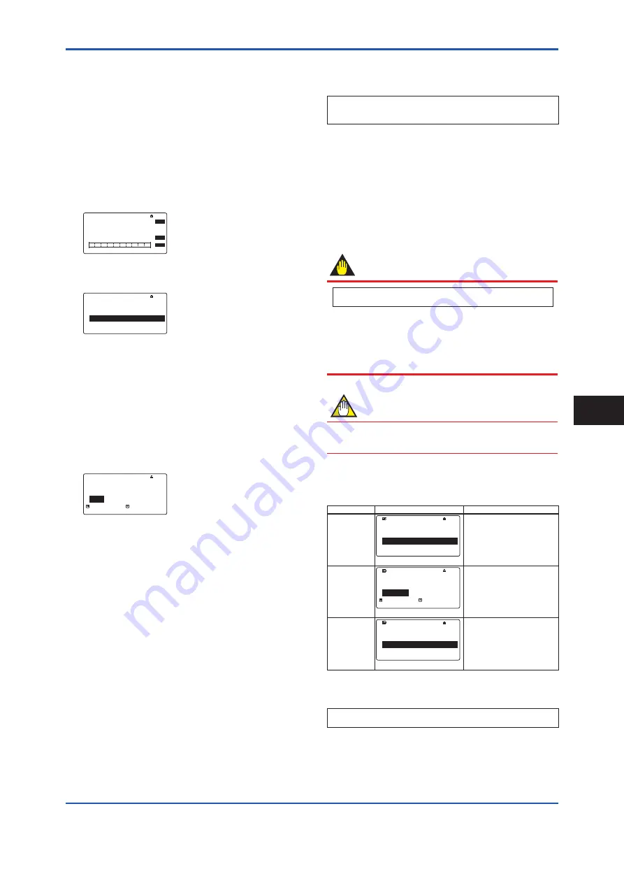
Parameter form

There are three types of parameter form below.

Type

Example of display

Contents

Select type

F0516.ai

Unit

 m

3

 l(liter)

 cm

3


00 : 00

SET

SFT

INC

Select the adequate data 
from among alternatives 
which are detemined in 
advance.

Numeric type

F0517.ai

Span

  +7200.00

  +2200.00

  +0.00001 +999999


00 : 00

SET

SFT

INC

Specify the data with a 

combination of number and a 

decimal point into each digit.

Alphanumeric 

type

F0518.ai

Tag No

  FT-1234

 FT-1234


00 : 00

SET

SFT

INC

Configure the data with a 
combination of alphanumeric 
characters. (Tag No., Special 

unit, etc…)

The alphanumeric type indicates alphanumeric 
characters in the following order. 

0123456789ABCDEFGHIJKLMNOPQRSTUVWXYZabcdefghijklmnopqrstu

vwxyz!"#$%&'()*+,-./:;<=>?@[\]^_`{|}~"space"

Basic Operating Procedures

5

Summary of Contents for ADMAG TI Series

Page 1: ...g to Remote Sensor and Remote Transmitter Sensor Side 42 4 6 Input and Output 45 5 Basic Operating Procedures 5 1 Operation by Display unit 48 5 2 Display and Basic Configuration 48 5 3 Display Mode and Setting Mode 51 5 4 Parameter Setting from Display Panel 52 5 5 microSD Card Setting 53 5 6 BRAIN Configuration Tool 54 5 7 HART Configuration Tool 54 5 8 Modbus Configuration Tool 55 5 9 FOUNDATIO...

Page 2: ...tic Flowmeter HART Communication Type IM 01E24A02 02EN ADMAG TI Series AXG AXW Magnetic Flowmeter Modbus Communication Type IM 01E21A02 05EN ADMAG TI Series AXG AXW Magnetic Flowmeter FOUNDATION Fieldbus Communication Type IM01E21A02 03EN ADMAG TI Series AXG1A Magnetic Flowmeter BRAIN Communication Type IM 01E22C02 01EN ADMAG TI Series AXG1A Magnetic Flowmeter HART Communication Type IM 01E22C02 0...

Page 3: ... personnel safety Do not modify this product YOKOGAWA will not be liable for malfunctions or damage resulting from any modification made to this product by the customer The product should be disposed of in accordance with local and national legislation regulations Regarding This User s Manual This manual should be provided to the end user The contents of this manual are subject to change without p...

Page 4: ...nance of the magnetic flowmeter must be performed by expert engineer or skilled personnel No operator shall be permitted to perform procedures relating to installation wiring and maintenance Wiring work should be done adequate wire sleeve crimp and torque force Use terminal with insulating cover for the power supply wiring and protective grounding wiring Do not pull the wires too much strongly in ...

Page 5: ...may damage the product s protection The flowmeter should be installed away from electrical motors transformers and other power sources in order to avoid interference with measurement WARNING Install an external switch or circuit breaker as a means to turn the power off capacitance 15A conforming to IEC60947 1 and IEC60947 3 Locate this switch either near the product or in other places facilitating...

Page 6: ...power Power Supply Code 1 AC Type Rated Power Supply 100 to 240 V AC 50 60 Hz DC Type Rated Power Supply 100 to 120 V DC Power Supply Code 2 AC Type Rated Power Supply 24 V AC 50 60 Hz DC Type Rated Power Supply 24 V DC Power Consumption Integral Type 13 W Remote Type with AXG4A 13 W Remote Type with AXG1A 32 W Note Power Consumption is independent of communication and I O specification Note For A...

Page 7: ...on our investigation The Purchaser shall bear the responsibility for repair costs even during the warranty period if the malfunction is due to Improper and or inadequate maintenance by the purchaser Failure or damage due to improper handling use or storage which is out of design conditions Use of the product in question in a location not conforming to the standards specified by YOKOGAWA or due to ...

Page 8: ...A JA M0 F0 1 pc Other code 0 pc 2 DA JA 2 pcs M6 0 pc Other code 1 pc 2 1 Model and Specifications Check As shown in Figure 2 1 to Figure 2 5 the model suffix code serial number meter factor fluid specification and device information are found on the name plate located on the outside of the housing And this product can check their information from parameters Read the user s manual of applicable co...

Page 9: ...e particle board attached until the flowmeter is install to the pipe Select a storage location that fulfils the following conditions A place where it will not be exposed to rain or water A place subject to minimal vibrations or shocks Temperature and humidity levels should be as follows Temperature 10 to 70 C Humidity 5 to 80 RH no condensation The preferred ambient temperature and humidity levels...

Page 10: ...ing the product in a place subject to shocks or vibrations 3 1 Piping Design Precautions IMPORTANT Design piping correctly referring to the following to prevent damage to sensors and to assure accurate measuring NOTE This section describes the remote sensor as an example The same attention must be paid to the integral flowmeter 1 Location IMPORTANT Install the flowmeter in a location where it is n...

Page 11: ...ANT Do not install the flowmeter where fluid conductivity tends to become uneven If chemicals are fed near the upstream side of a magnetic flowmeter they may affect the flow rate s indications To avoid this situation it is recommended that the chemical feed ports be located on the downstream side of the flowmeter If it is unavoidable that chemicals must be fed on the upstream side provide a suffic...

Page 12: ...e possibility of air bubbles F0305 ai Correct Incorrect Valve Correct Incorrect Figure 3 1 5 Avoiding Air Bubbles Mounting orientation IMPORTANT If electrodes are perpendicular to the ground air bubbles near the top or precipitates at the bottom may cause measurement errors Ensure that the terminal box of a remote sensor and transmitter of an integral flowmeter are mounted above the piping to prev...

Page 13: ...for a long term after installation If this situation is unavoidable take care of the flowmeter by observing the following Confirmation of sealing conditions for the flowmeter Confirm that the terminal box screw and cable entries are well sealed Equip the conduit piping with drain plugs or waterproof glands to prevent moisture or water from penetrating into the flowmeter through the conduit Regular...

Page 14: ...he flowmeter IMPORTANT If it is impossible to match the direction of the arrow mark the direction of the cable entry can be changed Read Section 3 5 In case the fluid being measured flows against the arrow direction change the value from Forward to Reverse at the parameter Flow direct Read the user s manual of the applicable communication type for AXW AXW4A AXG1A or the hardware software edition f...

Page 15: ...09 ai Screw Gasket Grounding ring Figure 3 3 1 Mounting of grounding ring Installation Natural hard rubber lining type and Metal pipe When a magnetic flowmeter with natural hard rubber lining is installed to metal pipe without lining installation method without grounding ring is recommended With grounding wire supplied by customer connect between the pipe and the sensor mini flange or between the ...

Page 16: ...nal box For grounding in detail read Subsection 4 4 3 In the case grounding ring is used for gasket A customer pipe side be sure to use non asbestos joint sheet gasket PTFE sheathed non asbestos joint sheet gasket optional code BSF or gasket with the equivalent hardness Installation without grounding ring Customer pipe Metal Customer pipe Metal F0312 ai With grounding wire connect between the pipe...

Page 17: ...tal mounting Figure 3 3 2 Mounting Procedure for Wafer Type sizes 25 32 and 40 mm 1 0 1 25 and 1 5 in F0315 ai Centering device four units Nut Through bolt Piping side flange Gasket Mini flange Housing Vertical mounting Horizontal mounting These items can be ordered optionally If they are provided by the user choose nuts and bolts in compliance with the flange ratings Figure 3 3 3 Mounting Procedu...

Page 18: ...thin sensor Natural Soft Rubber Polyurethane Rubber lining No gasket Standard Natural Hard Rubber lining Non asbestos gasket PTFE sheathed non asbestos gasket or the equivalent in hardness Gasket types for user s flange Non asbestos gasket PTFE sheathed non asbestos gasket Optional code BSF or the equivalent in hardness Flange Rating JIS 10K ASME Class 150 EN PN10 JIS 20K ASME Class 300 EN PN16 EN...

Page 19: ... and outer diameters that do not protrude inside the piping by referring to Subsection 3 3 3 WARNING All gaskets used for piping of magnetic flowmeters should be prepared by customers except in some cases For the following cases be sure to use a gasket between the grounding ring and the lining flare section to prevent fluid leaks Size 50 to 400 mm 2 to 16 in natural hard rubber lining and with gro...

Page 20: ...eter with PTFE or natural hard rubber lining is installed to metal pipe without lining the installation method without grounding ring is recommended Size 25 to 125 mm 1 to 5 in PTFE lining and without grounding ring are specified it is recommended to use no gasket between the pipe and the sensor With grounding wire supplied by customer connect between the pipe and the sensor flange or between the ...

Page 21: ...r gasket chloroprene rubber gasket or gasket with the equivalent hardness For gasket B sensor side use fluororubber gasket optional code GA GC or GD or gasket with the equivalent hardness It is recommended to use gasket with same hardness for gasket A and B Grounding ring Customer pipe Plastic Customer pipe Plastic A B F0322 ai A B Gasket A to be supplied by customer Gasket B to be supplied by cus...

Page 22: ...68 4 400 169 6 to 251 4 126 4 to 176 9 141 1 to 203 4 210 9 to 305 4 Tightening torque values for PTFE Natural Hard Rubber Natural Soft Rubber lining in lbf Gasket types within sensor Natural Soft Rubber lining No gasket Standard PTFE Natural Hard Rubber lining Non asbestos gasket PTFE sheathed non asbestos gasket or the equivalent in hardness Gasket types for user s flange Non asbestos gasket PTF...

Page 23: ...o 278 8 Tightening torque values for Polyurethane Rubber lining in lbf Gasket types within sensor No gasket Standard Gasket types for user s flange Non asbestos gasket PTFE sheathed non asbestos gasket or the equivalent in hardness Flange Rating JIS 10K ASME Class 150 EN PN10 JIS 20K ASME Class 300 EN PN16 EN PN40 JIS F12 Thread Standards Size in Metric screw Metric screw Unified screw Metric scre...

Page 24: ... 11 6 18 8 to 31 3 125 14 2 to 23 6 12 0 to 19 4 16 6 to 27 6 13 0 to 21 2 9 5 to 15 8 15 9 to 26 5 Tightening torque values for PTFE lining in lbf Gasket types within sensor Fluororubber gasket Optional codes GA GC or GD Gasket types for user s flange Fluororubber gasket chloroprene rubber gasket or the equivalent in hardness Flange Rating JIS 10K ASME Class 150 JIS 20K ASME Class 300 EN PN16 EN ...

Page 25: ...7 1 321 301 350 350 412 406 359 330 400 401 475 469 410 381 Unit inch Size Natural Hard Rubber Natural Soft Rubber Polyurethane Rubber Lining PTFE Natural Hard Rubber Natural Soft Rubber Polyurethane Rubber Lining Wafer Flange Inner Diameter for Effective Sealing øA Outer Diameter for Effective Sealing øB Recommended Inner Diameter of Gasket Minimum Inner Diameter of Gasket 2 Inner Diameter for Ef...

Page 26: ...her Screw U bolt Figure 3 4 1 2 inch Pipe Vertical Mounting 1 Fix the product on the mounting fixture using four screws 2 Fix the mounting fixture with the product installed on a 2 inch pipe using a U bolt Horizontal Pipe Mounting F0326 ai Mounting fixture 2 inch pipe Nut U bolt Washer Screw Figure 3 4 2 2 inch Pipe Horizontal Mounting 1 Fix the product on the mounting fixture using four screws 2 ...

Page 27: ...nting by the same process of AXG1A Please refer 3 4 3 for the process IMPORTANT Mounting fixture on equipment intended to be mounted on a wall or ceiling shall withstand a force of four times the weight of the equipment AXFA11 3 4 kg 7 5 lb 3 5 Changing Direction of Cable Entry IMPORTANT The following types can not be changed direction of cable entry after delivery Submersible Type Suffix code W F...

Page 28: ...ower to the flowmeter Using the wrench loosen the cover locking screw 1 See Figure 3 6 1 and Figure 3 6 2 clockwise to unlock the cover Upon shipment from the manufacturing plant the cover is locked Hold the flowmeter with your hand Remove the cover by rotating it counterclockwise WARNING When opening and closing the cover be sure to handle the cover carefully so that there are no damage and forei...

Page 29: ...lectric shocks and maintain performance do not remove safety cover 3 Installing the Cover Install the cover to the flowmeter by rotating the cover clockwise Tighten cover locking screw 1 See Figure 3 6 1 and Figure 3 6 2 counterclockwise using a hexagonal wrench nominal size 3 to lock the cover IMPORTANT When closing the cover close it with both hands until the cover does not turn in order to brin...

Page 30: ...CAUTION Terminate all the cable finish with crimp terminal of a round or rod shape depending on the shape of the terminal block and connect them reliably Always route the power and output signal cables in separate steel conduit tubes except when the power supply voltage is 24 V and four core cables are used for wiring For the remote type route the excitation cable and the signal cable in separate ...

Page 31: ...mp terminal Figure 4 2 1 Cable Finish for Excitaiton Cable NOTE For excitation cable and power cable always use a crimp terminal with an insulation cover Use crimp tools supplied by the manufacturer of the crimp terminal you want to use to connect the crimp terminal and cable Use crimp tools that are appropriate for the diameter of the cable to be connected 4 2 2 Dedicated Signal Cable AX01C F0402...

Page 32: ...plicable explosion protection type as listed in Table 1 1 This product is of watertight construction as stipulated in JIS C 0920 It is shipped with a wiring bracket waterproof gland waterproof gland with union or a plastic gland attached only in cases where an optional specification is selected for the cable entry Cable gland has the following kinds depending on the type and size Integral Type Flo...

Page 33: ...waterproof glands are recommended Do not over tighten the glands or damage to the cables may result Tightness of the gland can be checked by confirming that the cable is held firmly in place For working on the conduit or the flexible tubes G1 2 remove the waterproof gland and attach them directly to the cable entry 1 Waterproof Gland Integral Flowmeter Optional code EG2 EG3 Cable Waterproof gland ...

Page 34: ...asket Washer Tightening gland When working on conduit or flexible tube G1 2 only Cable G1 2 F0411 ai Remote Transmitter AXG1A AXFA11 Optional code EU5 AXG1A EU AXFA11 Gasket Washer Tightening gland When working on conduit or flexible tube G1 2 only Cable G1 2 F0412 ai 3 Plastic Gland Integral Flowmeter Optional code EP2 EP3 Plastic gland Gasket F0413 ai Remote Sensor Optional code EP F0414 ai Plas...

Page 35: ...or flexible tube G3 4 Extension plug x2 Cable G3 4 G1 2 Conversion plug x5 F0418 ai 4 3 2 Conduit Wiring When wiring the conduits utilize the waterproof gland to prevent water from flowing in through the conduit Place the conduit pipe on an angle as shown in the following figures Install a drain valve at the low end of the vertical pipe and open the valve regularly To prevent noise please do not u...

Page 36: ...or in other places facilitating easy operation Affix a Power Off Equipment label to this external switch or circuit breaker WARNING For explosion protection type products please be sure to read the user s manual of the applicable explosion protection type as listed in Table 1 1 Wiring Procedure 1 Check the product s power is off then remove the terminal cover transparent 2 Wire the power supply ca...

Page 37: ...le Cable length m ft Usable voltage range V F0425 ai Figure 4 4 3 Supply Voltage and Power Supply Cable Length AXG1A Remote Transmitter 3 Setting Power Supply Frequency IMPORTANT Set the local commercial power frequency in order to eliminate the effect of induction noise from the power supply For detailed parameter setting read the user s manual of the applicable communication type for AXW AXW4A A...

Page 38: ...ring fluid Moreover the potential must be the same as the ground The magnetic flowmeter is equipped with an grounding ring that makes a connection with the charge of the measured fluid for grounding and protects the lining Grounding rings are supplied with the products when specified with dedicated optional code Grounding Resistance 10 Ω or less Class C requirements Note When lightning protection ...

Page 39: ... matter Replace the cover in case the treads receive damages Replace the O ring if there is any scarring or transformation And apply silicone based grease at the O ring in case of the shortage and exhaustion of grease IMPORTANT When closing the cover close it with both hands until the cover does not turn in order to bring the housing and cover into tight contact Tighten while confirming that the c...

Page 40: ...Output Description Figure 4 4 11 Terminal Configuration AXW4A Remote Transmitter BRAIN HART Communication and I O code Connection Terminal BRAIN HART I O1 I O2 I O3 I O4 DA JA Iout1 Active P Sout1 Passive DE JE Iout1 Active P Sout1 Passive Sin No voltage P Sout2 Passive DG JG Iout1 Active P Sout1 Passive Sin No voltage P Sout2 Active Without resistor Modbus Communication and I O code Connection Te...

Page 41: ...t Two inputs PULSE OUT P Sout1 P Sout1 Pulse output EXCITATION EX1 EX2 Excitation current output POWER SUPPLY N L Power supply Functional grounding Protective grounding Outside of the terminal BRAIN HART Communication and I O code Connection Terminal BRAIN HART ALM Passive So11 So12 Passive Iout1 Active MIO Si11 Si12 No voltage P Sout1 Passive D0 J0 D2 J2 IinActive D3 J3 P Sout2 Passive D4 J4 P So...

Page 42: ...LARM OUT N L POWER SUPPLY EX2 EX1 EXCITATION P P PULSE OUT SIGNAL SI1 SI2 COM STATUS IN SO1 COM SO2 STATUS OUT Figure 4 4 15 Terminal Configuration AXFA11 Remote Transmitter Table 4 4 2 Terminal Symbols AXFA11 Remote Transmitter Terminal Symbol Description SIGNAL C SA A B SB Flow signal input ALARM OUT AL AL Alarm output STATUS OUT SO1 SO2 COM Status output Two outputs CURRENT OUT I I Current outp...

Page 43: ...ng plant the cover is unlocked Hold the sensor with your hand and remove the cover by turning it in the direction of the arrow as shown below F0441 ai 1 Figure 4 5 1 Removing the Terminal Box Cover Remote Sensor 2 Terminal Configuration When the cover is removed the connection terminals will be visible as shown below Remote Sensor To be wired to Remote Transmitter Non Explosion Protection Use F044...

Page 44: ... shown in the figure below AXG1A transmitter Transmitter Remote sensor F0444 ai SA A B SB C EX1 EX2 Taping A B Taping C EX1 EX2 Individually tape and insulate the shields corresponding to SA and SB on the remote sensor side Remote sensor EX2 EX1 A B C AX01C dedicated signal cable Excitation cable Figure 4 5 4 Wiring Diagram AXG1A Remote Transmitter 3 Connection with AXFA11 Remote Transmitter Conne...

Page 45: ...600 V vinyl insulated cable Cable cross section area 2 mm2 or larger Grounding Resistance 100 Ω or less Class D requirements F0446 ai CAUTION The grounding should satisfy grounding resistance requirement 100 Ω or less Class D grounding For explosion protection type the grounding must satisfy the domestic electrical requirements as regulated in each country F0447 ai In case grounding rings are used...

Page 46: ...Active current output lout Active pulse output P Sout Connection of an electronic counter Observe that maximum allowable voltage and voltage polarity are correct when wiring Load resistance 1 kΩ or more Internal power supply 24 V DC 20 Maximum pulse rate 10 000 pulses s Maximum frequency output rate 12 500 Hz P Sout 24 V Transmitter 0 V P Sout Electronic Counter Load Resistance F0449 ai Figure 4 6...

Page 47: ...iter observe that maximum allowable current voltage polarity and output current level are correct Load resistance External instruments 1 kΩ or more Internal power supply 24 V DC 20 P Sout 24 V Transmitter 0 V P Sout Load Resistance F0453 ai Figure 4 6 6 Connection diagram Active status output P Sout Passive status output P Sout or Sout So11 or So12 ALM Because of connecting to a transisiter observ...

Page 48: ...nal without voltage Loading voltage during the switching status Close may result in damage on the electrical circuit The status input is used for connecting to the following no voltage contacts Switching status Resistance Closed 200 Ω or less Open 100 kΩ or more Transmitter Sin Sin F0456 ai Figure 4 6 9 Connection diagram Status input Sin Wiring 4 ...

Page 49: ...p the cover closed and operate the setting switches from the outside of the glass window If dirt dust or other substances surfaces on the glass of display cover wipe them clean with a soft dry cloth The operation with dirty gloves may cause a switch response error NOTE The language on the display is set to English as default at the factory shipment Select the adequate language referring to the Sub...

Page 50: ...h 2 Explanation of display example F0502 ai Device address Baud rate Transmission mode R RTU A ASCII Stop bit 1 1 bit 2 2 bit Parity N None O Odd E Even Example R 001 19200 E 1 5 2 2 Basic Configuration for Display For paramter setting from display panel configurable parameters differ by the three operational levels specfied in Table 5 2 2 and a passcode is needed to enter into Setting mode No pas...

Page 51: ...e F0506 ai 0 50000 50 0 12 00 m s mA 00 00 VEL FLP AO1 SET SFT INC F0511 ai 00 00 FNL SET SFT INC Normal Long tag 1234567 TAG12345 LTG TAG Indicate 32 characters of the Long Tag in the first line Indicate 16 characters in the first half of 32 characters of the Long Tag in the second and third lines 4 line F0507 ai 0 50000 50 0 12 000 m s mA Normal 00 00 VEL AO1 FNL SET SFT INC FLP F0512 ai 00 00 F...

Page 52: ...wed only by parameter setting from the display unit Display Menu Path Device setup Detailed setup Access cfg Chg mainte Device setup Detailed setup Access cfg Chg special 1 Passcode for Maintenance operation level To change the passcode Maintenance code Maintenance or Specialist as the operational level is required 2 Passcode for Specialist operation level To change the passcode Specialist code Ma...

Page 53: ...he procedure of changing the flow rate unit as Select type parameter according to the specification of HART protocol The flow rate unit needs to be specified with Physical unit and Time unit individually When the flow rate unit needs to be set l min select l litter at the Physical unit and min at the Time unit Display Menu Path Device setup Detailed setup Pro var Volume Unit Device setup Detailed ...

Page 54: ...INC Specify the Tag No Move cursor with INC and DEC according to the menu path above and select the Order info then push SET F0527 ai Tag No FT 1234 FT 1234 00 00 SET SFT INC For Tag No up to 8 characters can be entered from display panel The switch s functionality of setting the Flow rate span is as below Plus minus and mumeric change INC Movement on digits SFT Determination of parameter SET Avai...

Page 55: ...ble 1 1 For explosion protection type the configuration tool should be connected at the safe site of no explosive atmosphere 5 7 HART Configuration Tool The connection of the HART configuration tool FieldMate Versatile Device Management Wizard is shown as below Read the user s manual of HART communication type as listed in Table 1 1 for the detailed parameter setting via HART communication NOTE Fo...

Page 56: ...ice and confirm the revision by the following parameter HART Communication Menu Path Device root menu Detailed setup Device information HART setup Fld dev rev 2 Device Type Manager DTM and Device Revision When configuring the parameters by FieldMate use the DTM Device Type Manager of the following table DTM Name AXW4A HART7 DTM AXG1A FDT2 0 HART7 DTM DTM Revision AXGWA 5 6 4 0 or later AXG1A 5 8 1...

Page 57: ...wer must be maintained F0532 ai Terminator Terminator Fieldbus power supply ADMAG TI HOST 5 9 2 FOUNDATION fieldbus Configuration Tool and Device Revision 1 If the host supports DD Device Description the DD of the AXG AXW needs to be installed Check if host has the following directory under its default DD directory If you do not have the DD or capabilities files you can download them from our web ...

Page 58: ...ing the valve Each time that the fluid being measured is changed be sure to carry out zero adjustment with the new fluid 6 2 Zero Adjustment from Display Unit A procedure of executing zero adjustment is as follows Display Menu Path Device setup Diag Service Autozero Execute Device setup Diag Service Autozero Result Zero value Enter the Setting Mode Read Section 5 3 For FOUNDATION fieldbus type set...

Page 59: ... 6 When opening the cover wait for more than 20 minutes after turning off the power This work must be carried out by the trained personnel having knowledge of safety standard To preserve the safety do not touch the electrical circuit and the cables except the setting switches When installing the cover in order to contact the housing and the cover be sure to screw it firmly into the housing without...

Page 60: ... Simulation Switch Only for FOUNDATION fieldbus communication The simulation function simulates the input of a function block and lets it operate as if the data was received from the transducer block It is possible to conduct testing for the downstream function blocks or alarm processes A SIMULATE_ENABLE switch is mounted in the transmitter amplifier This is to prevent the accidental operation of ...

Page 61: ... 6 is set to 1 the resulting the device address is 64 1 26 0 25 0 24 0 23 0 22 0 21 0 20 Setting of Line Termination Switch SW2 This switch is only available for the product with Modbus communication Line terminations of two ends on the bus are required to communicate Modbus One termination mode can be set using the line termination switch SW2 See Figure 6 3 1 Table 6 3 6 Line termination switch S...

Page 62: ...s where the optional codes C1 or C2 have been specified the output direction will be set to Low i e 2 4 mA Modification of the burnout direction must be carried out using the burnout switch i e Switch 1 1 See Figure 6 3 4 Table 6 3 8 Burnout switch Switch 1 1 Position of Switch Burnout Direction Burnout Output Description 1 2 ON L OFF H High 21 6 mA When optional code C1 or C2 is not specified the...

Page 63: ...n when making switch settings 1 Setting of Burnout Switch The burnout function sets the direction of current output in situations where the CPU has become damaged Upon shipment from the manufacturing plant the burnout direction is set to High i e 25 mA however in cases where the optional codes C1 have been specified the output direction will be set to Low i e 0 mA Modification of the burnout direc...

Page 64: ...r of pulse width modulation 1 was detected Contact Yokogawa service center F 022 PWM 2 stop Error of pulse width modulation 2 was detected Contact Yokogawa service center F 023 Opt bd mismatch Mismatch of option board was detected Contact Yokogawa service center F 024 Opt bd EEP FAIL Failure of EEPROM option board was detected Contact Yokogawa service center F 025 Opt bd A D FAIL Failure of A D op...

Page 65: ...T VALUE and configuration of AI2 Lo Lo Lim AI2 LO_LO_LIM AI2 Lo Lo Pri AI2 LO_LO_PRI N 370 AI2 Hi Alarm High Alarm has occurred Check the AI2 Output Value AI2 OUT VALUE and configuration of AI2 Hi Lim AI2 HI_LIM AI2 Hi Pri AI2 HI_PRI N 371 AI2 Lo Alarm Low Alarm has occurred Check the AI2 Output Value AI2 OUT VALUE and configuration of AI2 Lo Lim AI2 LO_LIM AI2 Lo Pri AI2 LO_PRI N 372 AI3 HH Alarm...

Page 66: ... MODE_BLK Target to Auto or other mode C 301 AI1 Man Mode AI1 Block is in Man mode Change the AI1 Block Mode Target AI1 MODE_BLK Target to Auto or other mode C 302 AI1 Not Schedule AI1 Block is not scheduled ScheduleAI1 Block C 303 AI1 Simulate Act AI1 block is in simulation mode Change the AI1 Simulation En Disable AI1 SIMULATE SIMULATE_ ENABLE to Disabled C 304 AI2 O S Mode AI2 Block is in O S m...

Page 67: ...t to Auto or other mode C 349 DI3 Man Mode DI3 Block is in Man mode Change the DI3 Block Mode Target DI3 MODE_BLK Target to Auto or other mode C 350 DI3 Not Schedule DI3 Block is not scheduled ScheduleDI3 Block C 351 DI3 Simulate Act DI3 block is in simulation mode Change the DI3 Simulation En Disable DI3 SIMULATE SIMULATE_ ENABLE to Disabled C 352 AR O S Mode AR Block is in O S mode Change the AR...

Page 68: ...nt output 2 Check current output 2 is test mode or not S 098 Pls 1 fix It was detected that fixied value is set to Pulse output 1 Check pulse output 1 is test mode or not S 099 Pls 2 fix It was detected that fixied value is set to Pulse output 2 Check pulse output 2 is test mode or not S 100 AI fix It was detected that fixied value is set to Current input Check current input is test mode or not C ...

Page 69: ...or Modbus communication type Add trademark informations HART Modbus Revise the table for blanking plug quantity Add the installation location precautions Add the WARNING for explosion protection type Add the explanation of cable for Modbus communication Add the table for connection terminal for Modbus communication type Add the explanations for Modbus communication Add the explanation of Modbus co...

Reviews: