background image


YMC Europe GmbH 

Operation 

YMC Pilot 

30 / 49 


Low pressure chromatography column 

6.4.2 

Slurry column packing under flow 


  The column is packed with the slurry method under flow as follows: 

1.  Remove the adjustable end piece  Chapter 6.3.1, p. 27. 

2.  Tighten the O-ring of the fixed end piece  Chapter 6.1, p. 26. 

3.  Connect the pump / system with the tubing to the fixed end piece. 

4.  Start the pump. 

5.  Fill the glass body with solvent or buffer until 2-3 cm above the frit of the fixed 

end piece (bottom-up). 

  This ensures that no air is trapped under or inside the frit.  

6.  Close the valve on the tubing of the fixed end piece.  

7.  Connect the pump to the adjustable end piece. 

8.  Flush  the  piston  of  the  adjustable  end  piece  with slurry  solvent  until  the  frit  in 

the adjustable end piece is wetted completely.  

9.  Disconnect the pump from the adjustable end piece.  

10.  Pour the homogenous and / or degassed slurry into the glass body. 

11.  Rinse the inner wall of the column body with slurry solvent to remove particles 

from the walls.  

  By removing particles from the inner wall of the column body, a correct seal 

with the O-ring is guaranteed.  

12.  Fill the glass column up to the edge of the column body with slurry solvent.  

13.  Loosen the O-ring of the adjustable end piece.  

14.  Insert the adjustable end piece with loosened O-ring into the column. 

  By  inserting the adjustable end piece  with loosened  O-ring into  the solvent, 

the risk of air bubbles below the frit is reduced.  

  Check that no air bubbles are below the frit. 

15.  Turn the cylinder screws with the hex-wrench through the closing disc into the 

column disc. This way, the column is closed.  

16.  Tighten the O-ring of the adjustable end piece.  

17.  Open the valve in the tubing on the adjustable end piece.  

18.  Turn  the  piston  of  the  adjustable  end  piece  in  the  down  direction  until  the 

tubing is completely filled with liquid.  

  The tubing is now free of air.  

19.  Connect the pump with the tubing to the adjustable end piece.  

20.  Open the valve in the tubing of the fixed end piece.  

21.  Start the flow (top-down).  

22.  Increase  the  flow  rate  stepwise  until  the  desired  pressure  /  flow  rate  is 

reached.  Wait  after  every  step  until  the  pressure  is  constant.  Afterwards,  the 
flow rate can be further increased.  

  Consider the manufacturer´s recommendations for the packing material.  

  The  flow  rate  should  be  considerably  (>20%)  higher  than  the  required 

operating flow rate.  

Summary of Contents for Pilot

Page 1: ...YMC Pilot In order to avoid personal injuries and damage to equipment please read this manual carefully and act on the recommendations given Keep this manual accessible for the user at all times Vers...

Page 2: ...YMC Europe GmbH Sch ttmannshof 19 46539 Dinslaken Deutschland 49 02064 427 0 Info ymc de www ymc de YMC Europe GmbH YMC Pilot 2 49 Low pressure chromatography column...

Page 3: ...Adjustable end piece 15 3 4 2 Piston front 18 3 4 3 Fixed end piece 19 3 4 4 Column body 21 4 Delivery 22 4 1 Delivery contents 22 4 2 Delivery inspection 22 5 Requirements for operation 23 5 1 Safet...

Page 4: ...eplacement 40 7 4 2 O ring plunger replacement 40 7 4 3 Replacing the glass body 41 8 Troubleshooting 42 9 Storage packaging and transport 44 9 1 Storage 44 9 2 Transport 44 10 Disposal 45 11 Appendix...

Page 5: ...oured signal word fields Always read the full text of the warning in order to effectively protect yourself from damage The following signal word fields are marked by different colours and signal words...

Page 6: ...of the action step to check whether the step has been performed correctly 2 Another action step Figures within instructions A figure is only related to the action step which is listed directly below t...

Page 7: ...tmospheric pressure at the intended maximum temperature 40 C Every use which is outside these specifications is defined as not intended use The intended use includes the compliance with the advice and...

Page 8: ...ended personal protective equipment The following protective equipment is required Symbol PPE Phase of life Action Protective gloves Operation Column packing Column unpacking Initiation Cleaning Safet...

Page 9: ...epending on the column version 3 2 Specifications PED fluid group Group 1 referred to EU Guideline 2014 68 EU PED safety requirement Article 4 3 of EU Guideline 2014 68 EU Available versions AB versio...

Page 10: ...65x55 45x42 48x44 60x50 65x55 Maximum co lumn height mm 1750 1750 1800 1920 2100 2100 2150 2270 1depending on packing material and packing method 3 2 2 Specifications SR version Length glass body mm...

Page 11: ...ical resistance of the column can be concluded Such statements are based on our current technical knowledge and experiences as well as on existing literature and the information from the commodity pro...

Page 12: ...loromethane Good Limited Good Unstab le Unstab le Good Limited 0 1 M EDTA 3 Good Good Good Good Good Good Good 1 M Acetic acid 6 Good Good Good Good Good Good Good Ethanol Good Good Good Good Good Goo...

Page 13: ...phosphate Good Good Limited Good Good Cyclohexane Good Good Good Good Good Dichloromethane Good Good Good Good Good 0 1 M EDTA 3 Good Good Good Good Good 1 M Acetic acid 6 Good Good Limited Good Good...

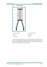
Page 14: ...l parts listed for the column body and the end pieces are in the appendix The glass column consists of the adjustable end piece 1 the column body 2 the fixed end piece 3 and the column stand The colum...

Page 15: ...piece the internal and external spindle the plunger the frit and the O ring The tubing passes through the internal spindle to the plunger With the handle bar in the closing disc the piston can be adj...

Page 16: ...tersunk screw 3 Set screw 17 Frit 4 Tension nut 18 O ring frit 5 Teflon disc 19 Handle bar 6 Set screw 20 Cylinder screw 7 Connection nut outer spindle 21 Internal spindle AEP 8 Adapter rotary handle...

Page 17: ...liding disc small 6 Coupler plunger 23 Sliding disc big 7 Distributor plate 24 Threaded insert eye bolts 8 O ring coupler 25 Eye bolt 9 Pressure piece 26 Connection nut outer spindle 10 Sealing washer...

Page 18: ...4 O ring frit The piston front design is the same for the adjustable and the fixed end pieces The piston front consists of the plunger 3 and the pressure piece 1 which is located on springs on the plu...

Page 19: ...By turning the tension nut the O ring is compressed or relaxed and this way the seal is tightened or loosened The closing disc FEP is connected with the column disc FEP via cylinder screws 3 4 3 1 Fi...

Page 20: ...EP 14 Cylinder screw 3 Tension nut 15 Threaded insert 4 Connection nut inner spindle 16 Coupler plunger 5 Set screw 17 Sealing washer 6 Tubing 18 O ring coupler 7 Teflon disc 19 Distributor plate 8 Cy...

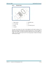
Page 21: ...Rod 5 Main pillar 3 Glass body 6 Castor The glass body is fixed between the column disc AEP and the column disc FEP by the rods The column body is equipped with wheels The two end pieces can be insert...

Page 22: ...lity Control If ordered especially separately Material certificates statements of conformity 4 2 Delivery inspection YMC recommends retaining and storing the original packaging and the foam cushion so...

Page 23: ...lumn only with pressures within the stated specifications Otherwise there is a risk of injury and material damage CAREFUL The temperature range which is used must not exceed fall below the given speci...

Page 24: ...ring work on the glass column wear the prescribed personal protective equipment WARNING Glass column under high pressure Eye or skin injuries possible due to remaining pressure in the tubing or in the...

Page 25: ...bottom up 4 When the column is filled with liquid completely close gate valve 3 5 Build up the testing pressure with a flow rate of 25 50 mL min The testing pressure is the pressure limit of the colum...

Page 26: ...he direction of the external spindle or the connection nut outer spindle The O ring is squeezed O ring is sealed when a constant black line appears in the glass body The O ring is loosened as follows...

Page 27: ...s 1 Turn the adjustable end piece in up direction as far as it will go 2 Loosen the O ring of the adjustable end piece by turning the tension nut in up direction 3 Remove the cylinder screws from the...

Page 28: ...packing method to the manufacturer s packing material information Improper packing conditions can cause damage or completely destroy the material ATTENTION Avoid the use of a magnetic stirrer Dependin...

Page 29: ...mn The slurry is prepared as follows 1 Mix the solvent or buffer with the appropriate amount of packing material in a suitable container see manufacturer s recommendations The total volume of the slur...

Page 30: ...with the O ring is guaranteed 12 Fill the glass column up to the edge of the column body with slurry solvent 13 Loosen the O ring of the adjustable end piece 14 Insert the adjustable end piece with lo...

Page 31: ...r until 2 3 cm above the frit in the fixed end piece bottom up This ensures that no air is trapped under or inside the frit 6 Close the valve in the tubing of the fixed end piece 7 Pour the homogenous...

Page 32: ...sed Consider the manufacturer s recommendations for the packing material The flow rate should be considerably 20 higher than the required operating flow rate The column bed is visually compressed 24 C...

Page 33: ...asher 4 Threaded insert 11 Cylinder screw 5 Nut 12 Coupling disc 6 Column disc AEP 13 O ring glass body 7 Rod The packing adapter is assembled as follows 1 Remove the adjustable end piece Chapter 6 3...

Page 34: ...ment CAREFUL Packing material Eye and skin injuries possible through contact with packing material Wear the prescribed personal protective equipment The glass column is unpacked under flow as follows...

Page 35: ...perating pressure Only authorised and qualified personnel should carry out the maintenance WARNING Incorrect replacement of spare parts Severe injuries due to breakage possible if unauthorised spare p...

Page 36: ...the contamination three different procedures can be used 1 Regeneration 2 Sterilisation 3 Depyrogenation Regeneration Regeneration removes inorganic and organic contamination which binds to the chroma...

Page 37: ...ents lipopolysaccharides and other lipophilic substances Very good Good 7 2 Cleaning and maintenance plan The specified maintenance plan here is to be regarded as a general recommendation Depending on...

Page 38: ...pment CAREFUL Packing material Eye and skin injuries possible through contact with packing material Wear the prescribed personal protective equipment Devices required Wetted and lint free rags Collect...

Page 39: ...r wall of the column body 4 Clean the column body with an authorised cleaning agent and a wetted lint free rag 5 Put a collection vessel below the column body 6 Connect the pump to the tubing from the...

Page 40: ...ghten on the opposite sites Take care during assembly of the glass body that all parts are correctly aligned 7 4 1 Frit replacement The frits in the adjustable and fixed end pieces are replaced as fol...

Page 41: ...te sites 3 Remove the cap nuts and washers 4 Remove the column disc from the column body Remove the O ring glass body 5 Remove the glass body carefully 6 Position the new glass body on the O ring glas...

Page 42: ...Stressed column packing Peak shape of the eluted substances deteriorates Dead volume at the column inlet See fault description Dead volume occurred Partially clogged frit Frit replacement Chapter 7 4...

Page 43: ...eck if solvent leaks between glass body and O ring 2 Check contact surface of the glass body and the sealing surface for impurities 3 Check the torque and the concentric arrangement of the parts Tubin...

Page 44: ...ld be stored as follows unpacked cleaned dry empty 9 2 Transport We recommend the use of the original wooden box for transportation If you are no longer in possession of the box please pack the column...

Page 45: ...sposal YMC Pilot 45 49 Low pressure chromatography column 10 Disposal For the disposal of the glass column it has to be disassembled and disposed according to the national and other applicable environ...

Page 46: ...PI140 500 Glass body Borosilicate glass 3 33 4 140 PI140 850 Glass body Borosilicate glass 3 3 5 200 PI200 500 Glass body Borosilicate glass 3 3 6 200 PI200 850 Glass body Borosilicate glass 3 3 7 300...

Page 47: ...mm Countersunk screw frit PEEK 5 100 PI100AB115PE 10 Frit PE 6 100 PI100AB102E O ring frit EPDM 7 100 140 200 300 PI034 AB Connector PVDF PEEK PTFE 8 100 140 200 300 PI034 DS Sealing washer connector...

Page 48: ...5 100 PI100SR110SS 10 Frit Stainless steel 1 4404 6 100 PI100SR102K O ring frit Kalrez 7 100 140 200 300 PI034 SR Connector Stainless steel 1 4404 8 100 140 200 300 PI034 DS Sealing washer connector...

Page 49: ...lass body replacement 41 P Packaging 44 Packing 28 Packing adapter 33 Personal protective equipment 8 Pressure test 24 Protective equipment 8 R Resistance chemical 11 S Signal word 5 Signal word field...

Reviews: