


A.2 Drive Specifications
Note:
1.
Perform rotational Auto-Tuning to obtain the performance specifications given below.
2.
For optimum performance life of the drive, install the drive in an environment that meets the required specifications.
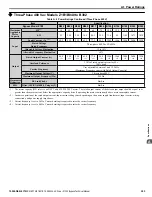
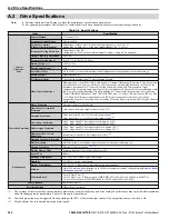
Table A.5 Specifications
Item
Specification
Control
Character-
istics
Control Method
V/f Control (V/f)
Frequency Control Range
0.01 to 240 Hz
Frequency Accuracy
(Temperature Fluctuation)
Digital input: within ±0.01% of the max output frequency (-10 to +50 °C)
Analog input: within ±0.1% of the max output frequency (25 °C ±10 °C)
Frequency Setting Resolution
Digital inputs: 0.01 Hz
Analog inputs: 1/1000 of the maximum output frequency setting (10 bit unsigned)
Output Frequency Resolution
0.001 Hz
Frequency Setting Signal
0 to 10 V, 0 to 20 mA, 4 to 20 mA
140% at 3 Hz
Speed Control Range
1:40
Accel/Decel Time
0.0 to 6000.0 s (4 selectable combinations of independent acceleration and deceleration settings)
Braking Torque
Approximately 20%
V/f Characteristics
User-selected programs and V/f preset patterns possible
Main Control Functions
Momentary Power Loss Ride-Thru, Speed Search, Overtorque/Undertorque Detection, 4 Step Speed (max),
Accel/Decel Switch, S-curve Accel/decel, 3-Wire Sequence, Auto-Tuning (Stationary for Line-to-Line
Resistance, Rotational for V/f Control), Cooling Fan on/off Switch, Slip Compensation, Torque
Compensation, Frequency Jump, Upper/lower Limits for Frequency Reference, DC Injection Braking at Start
and Stop, Overexcitation Braking, High Slip Braking, PI Control (with sleep function), Energy Saving
Control, MEMOBUS/Modbus Comm. (RS-422/RS-485 max, 115.2 kbps), BACnet Comm. (RS-485 max.
115.2 kbps), Fault Restart, Application Presets, KEB, Overexcitation Deceleration, Overvoltage
Suppression, Sequence Timer Operation, Secondary PI Control, Bypass Operation, HOA Keypad, Dynamic
Noise Control
Protection Functions
Motor Protection
Electronic thermal overload relay
Momentary Overcurrent
Protection
Drive stops when rated output current exceeds 175%
Overload Protection
Drive stops after 60 s at 110% of rated output current
Drive stops after 0.5 s at 140% of rated output current
Overvoltage Protection
208 V: Stops when DC bus voltage exceeds approx. 410 V
480 V: Stops when DC bus voltage exceeds approx. 820 V
Undervoltage Protection
208 V: Stops when DC bus voltage falls below approx. 190 V
480 V: Stops when DC bus voltage falls below approx. 440 V
Momentary Power Loss
Ride-Thru
Immediately stop after 15 ms or longer power loss
Heatsink Overheat Protection
Thermistor
Stall Prevention
Stall Prevention is available during acceleration, deceleration, and during run.
Ground Protection
DC Bus Charge LED
Remains lit until DC bus voltage falls below 50 V
Environment
Area of Use
Indoors
Ambient Temperature
-10 °C to +40 °C NEMA Type 1 Enclosure
Humidity
95% RH or less (no condensation)
Storage Temperature
-20 °C to 70 °C (short-term temperature during transportation)
Altitude
Up to 1000 meters without derating, up to 3000 m with output current and voltage derating.
for details.
Vibration/Shock
10 to 20 Hz at 9.8 m/s
2
20 to 55 Hz at 5.9 m/s
2
(Drive models CIMR-Z
o
2A0011 to 2A0031 and 4A0005 to 4A0027) or
2.0 m/s
2
(Drive Models CIMR-Z
o
2A0046 to 2A0396 and 4A0034 to 4A0590)
Safety Standard
IEC/EN 61800-5-1
Protection Design
NEMA Type 1 enclosure
and with changing motor temperature. Contact Yaskawa for consultation.
<2> Overload protection may be triggered when operating with 100% of the rated output current if the output frequency is less than 6 Hz.
<3> May be shorter due to load conditions and motor speed.
A.2 Drive Specifications
304
YASKAWA ELECTRIC SIEP YAIZ1B 01E YASKAWA AC Drive – Z1000 Bypass Technical Manual


