


PI feedback value
PI
Feedback
Detection
Loss Level
(b5-13)
PI Feedback
Loss Detection Time
(b5-14)
No FbL
detection
FbL detection
Time
PI Feedback
Loss Detection Time
(b5-14)
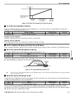
Figure 5.13 PI Feedback Loss Detection
n
b5-12: PI Feedback Loss Detection Selection
Enables and disables the feedback loss detection and sets the operation when a feedback loss is detected.
No.
Parameter Name
Setting Range
Default
b5-12
PI Feedback Loss Detection Selection
0 to 5
0
Setting 0: Digital Output Only
A digital output set for “PI feedback low” (H2-
oo
= 3E
<1>
) will be triggered if the PI feedback value is below the detection
level set to b5-13 for the time set to b5-14 or longer. A digital output set for “PI feedback high” (H2-
oo
= 3F
<1>
) will be
triggered if the PI feedback value is beyond the detection level set to b5-36 for longer than the time set to b5-37. Neither a
fault nor an alarm is displayed on the HOA keypad and the drive will continue operation. The output resets when the feedback
value leaves the loss detection range.
Setting 1: Feedback Loss Alarm
If the PI feedback value falls below the level set to b5-13 for longer than the time set to b5-14, a “FBL - Feedback Low” alarm
will be displayed and a digital output set for “PI feedback low” (H2-
oo
= 3E
<1>
) will be triggered. If the PI feedback value
exceeds the level set to b5-36 for longer than the time set to b5-37, a “FBH - Feedback High” alarm will be displayed and a
digital output set for “PI feedback high” (H2-
oo
= 3F
<1>
) will be triggered. Both events trigger an alarm output
(H1-
oo
= 10). The drive will continue operation. The alarm and outputs reset when the feedback value leaves the loss detection
range.
Setting 2: Feedback Loss Fault
If the PI feedback value falls below the level set to b5-13 for longer than the time set to b5-14, a “FbL - Feedback Low” fault
will be displayed. If the PI feedback value exceeds the level set to b5-36 for longer than the time set to b5-37, a “FbH - Feedback
High” fault will be displayed. Both events trigger a fault output (H1-
oo
= E
<1>
) and cause the drive to stop the motor.
Detection remains active when PI is disabled by digital input (H1-
oo
= 19).
Setting 3: Digital Output Always
Same as Setting 0, except that PI must be active and the drive must be running.
Setting 4: Alarm Always
Same as Setting 1, except that PI must be active and the drive must be running.
Setting 5: Fault Always
Same as Setting 2, except that PI must be active and the drive must be running.
<1> Details on this function can be found in the standard Z1000 Programming Manual (SIEPC71061645) at
www.yaskawa.com.
n
b5-13: PI Feedback Low Detection Level
Sets the feedback level used for PI feedback low detection. The PI feedback must fall below this level for longer than the time
set to b5-14 before feedback loss is detected.
No.
Name
Setting Range
Default
b5-13
PI Feedback Low Detection Level
0 to 100%
0%
5.2 b: Application
YASKAWA ELECTRIC SIEP YAIZ1B 01E YASKAWA AC Drive – Z1000 Bypass Technical Manual
133
5
Programming


