1.
1. Check the E2-02 and E2-03 values in Verify Mode or Parameter Setting Mode.
2.
Operate the motor in Drive Mode with the following conditions:
Do not disconnect the wiring between the motor and drive.
Do not lock the motor shaft with a mechanical brake or other device.
The maximum motor load should be 30% of the rated load.
Maintain a constant speed of 30% of E1-06 (base frequency, default value = maximum frequency) or higher for one second
or longer.
3.
After the motor is stopped, recheck the E2-02 and E2-03 values in Verify Mode or Parameter Setting Mode.
4.
Confirm that the input data is correct.
Note:
1.
If the aforementioned conditions are not met before using the motor for the first time, there will be large discrepancies between the
values set for the motor rated slip (E2-02), motor no-load current (E2-03), the motor test report, and the default values based on o2-04,
Drive Model Selection and C6-01, Drive Duty Rating.
2.
If midway initialization is performed, restart the entire tuning procedure from the beginning.
3.
Use the following guidelines for a general-purpose motor: Motor rated slip (E2-02): 0.5 Hz to 3 Hz; Motor no-load current (E2-03):
30% to 65% of the rated current. Generally speaking, for larger motor capacities, the rated slip is smaller and the no-load current as a
percentage of the rated current is smaller.
Refer to Defaults by Drive Model and Duty Rating ND/HD on page 588
Stationary Auto-Tuning for Line-to-Line Resistance and PM Motor Stator Resistance
• Perform when entering motor data manually while using motor cables longer than 50 m.
• If the motor cables have been replaced with cables more than 50 m long after Auto-Tuning has already been performed, use
Stationary Auto-Tuning for line-to-line resistance.
WARNING! Electrical Shock Hazard. When executing Stationary Auto-Tuning for Line-to-line resistance, voltage is applied to the motor
even before it rotates. Do not touch the motor until Auto-Tuning is completed. Failure to comply may result in injury or death from electrical
shock.
n
Notes on Inertia Tuning and ASR Gain Auto-Tuning
WARNING! Electrical Shock Hazard. When executing Inertia Tuning or ASR Gain Auto-Tuning, voltage is applied to the motor even before
it rotates. Do not touch the motor until Auto-Tuning is completed. Failure to comply may result in injury or death from electrical shock.
• Perform both tuning methods with the machine connected to the motor, but without the load applied.
• The motor will rotate during the Auto-Tuning process. Make sure the areas around the motor and connected machinery are
clear.
• The drive will let the system rotate at a certain speed while superimposing a sine wave test signal. Make sure this tuning
process does not cause any problem or malfunction in the machine before using it.
• Ensure the motor-mounted brake is fully released if installed.
• Connected machinery should be allowed to rotate the motor.
u
Auto-Tuning Interruption and Fault Codes
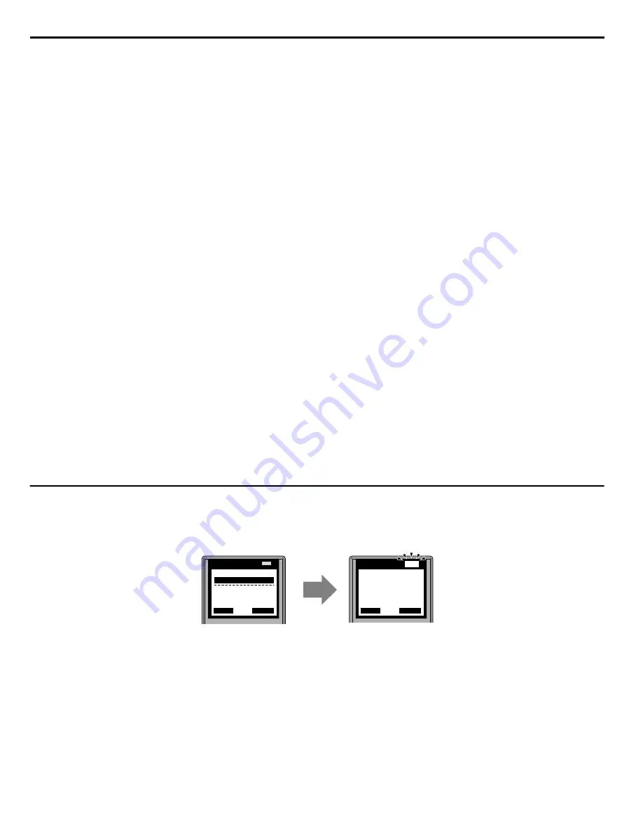
If tuning results are abnormal or the STOP key is pressed before completion, Auto-Tuning will be interrupted and a fault code
will appear on the digital operator.
B
LO
RE
ESC
RUN
STOP
ENTER
RESET
DIGITAL OPERATOR JVOP-180
A
LO
RE
ESC
RUN
STOP
ENTER
RESET
DIGITAL OPERATOR JVOP-180
ALM
ALM
- A.TUNE -
X.XX Hz/ X.XXA
DRV
Tune Proceeding
Rdy
FWD
<
<<
<<< >>>
>>
>
- MODE -
Er-03
STOP key
DRV
FWD
RESET
A – During Auto-Tuning
B – Auto-Tuning Aborted
Figure 4.13 Auto-Tuning Aborted Display
4.7 Auto-Tuning
162
YASKAWA ELECTRIC SIEP C710636 04D U1000 Industrial MATRIX Drive Technical Manual
Summary of Contents for U1000 iQpump Drive
Page 705: ......


