
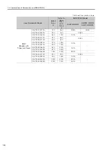


3.2 Ratings and Specifications
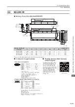
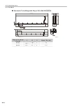
3.2.7 Force-Motor Speed Characteristics
3-10
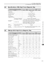
*1.
These values are for operation in combination with a SERVOPACK when the temperature of the armature wind-
ing is 100
°
C. The values for other items are at 20
°
C. These are typical values.
*2.
The rated forces are the continuous allowable force values at a surrounding air temperature of 40
°
C with an alu-
minum heat sink of the dimensions given in the following table.
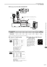
•
Heat Sink Dimensions
•
200 mm
×
300 mm
×
12 mm: SGLGW-40A140C and -60A140C
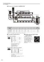
•
300 mm
×
400 mm
×
12 mm: SGLGW-40A253C and -60A253C
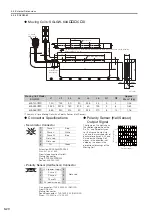
•
400 mm
×
500 mm
×
12 mm: SGLGW-40A365C and -60A365C
*3.
To externally connect dynamic brake resistor, select hardware option specification 020 for the SERVOPACK.
However, you cannot externally connect dynamic brake resistor if you use the following SERVOPACKs (maxi-
mum applicable motor capacity: 400 W).
•
SGD7S-R70
A020 to -2R8
A020
•
SGD7W-1R6A20A020 to -2R8A20A020
•
SGD7C-1R6AMAA020 to -2R8AMAA020
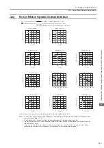
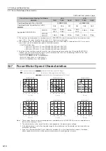
3.2.7
Force-Motor Speed Characteristics
Note: 1. These values (typical values) are for operation in combination with a SERVOPACK when the temperature of
the armature winding is 100°C.
2. The characteristics in the intermittent duty zone depend on the power supply voltage.
3. If the effective force is within the allowable range for the rated force, the Servomotor can be used within the
intermittent duty zone.
4. If you use a Servomotor Main Circuit Cable that exceeds 20 m, the intermittent duty zone in the torque-
motor speed characteristics will become smaller because the voltage drop increases.
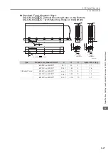
Combined Magnetic Way, SGLGM-
40
C
-M
60
C
-M
Combined Serial Converter Unit, JZDP-
-
255
256
257
261
262
263
Applicable SERVOPACKs
SGD7S-
1R6A,
2R1F
2R8A,
2R8F
3R8A
1R6A,
2R1F
3R8A
7R6A
SGD7W-
SGD7C-
1R6A
2R8A
5R5A
1R6A
5R5A
7R6A
Continued from previous page.
Linear Servomotor Moving Coil Model
SGLGW-
40A
60A
140C
253C
365C
140C
253C
365C
S
GLGW-40A140C
0
1
2
3
4
5
A
B
A
B
A
B
S
GLGW-40A25
3
C
0
1
2
3
4
5
S
GLGW-40A
3
65C
0
1
2
3
4
5
A
B
A
B
A
B
S
GLGW-60A25
3
C
S
GLGW-60A140C
5
4
3
2
1
0
S
GLGW-60A
3
65C
5
4
3
2
1
0
5
4
3
2
1
0
0
200
400
600
800
0
100
200
3
00
400
500
0
250
150
200
50
100
200
400
600
800
0
0
0
400
240
3
20
80
160
240
480
720
960
1200
Force (N)
Motor
s
peed (m/
s
)
Force (N)
Motor
s
peed (m/
s
)
Force (N)
Motor
s
peed (m/
s
)
Force (N)
Motor
s
peed (m/
s
)
Force (N)
Motor
s
peed (m/
s
)
Force (N)
Motor
s
peed (m/
s
)
(da
s
hed-dotted line
s
): With
s
ingle-pha
s
e 100-V input
(dotted line
s
): With
s
ingle-pha
s
e 200-V input
(
s
olid line
s
): With three-pha
s
e 200-V input
Intermittent duty zone
Continuou
s
duty zone
A :
B :