


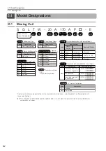
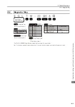


5.1 Model Designations
5.1.3 Precautions on Moving Coils with Polarity Sensors (Hall Sensor)
5-4
5.1.3
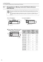
Precautions on Moving Coils with Polarity Sensors
(Hall Sensor)
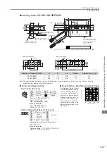
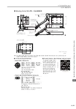
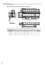
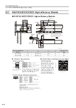
When you use a Moving Coil with a Polarity Sensor (Hall Sensor), the Magnetic Way must cover
the bottom of the polarity sensor (hall sensor). Refer to the example that shows the correct instal-
lation.
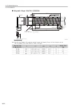
When determining the length of the Moving Coil’s stroke or the length of the Magnetic Way, con-
sider the total length of the Moving Coil and the polarity sensor (hall sensor). Refer to the follow-
ing table.
Correct Installation
Incorrect Installation
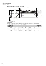
Total Length of Moving Coil with
Polarity Sensor (Hall Sensor)
Note
Moving Coil
Polarity sensor
(hall sensor)
Magnetic Way
Moving Coil
movement direction
Edge of Magnetic Way
Polarity sensor
(hall sensor)
Edge of Magnetic Way
Magnetic Way
Polarity sensor
(hall sensor)
Moving Coil
L
L1
A
Moving Coil
Model
SGLTW-
Length of
Moving
Coil,
L1 [mm]
Length of
Polarity
Sensor
(Hall Sensor),
A [mm]
Total
Length,
L [mm]
20A170AP
170
34
204
20A320AP
315
349
20A460AP
460
494
35A170AP
170
34
204
35A320AP
315
349
35A460AP
460
494
35A170HP
170
34
204
35A320HP
315
349
50A170HP
170
34
204
50A320HP
315
349
40A400BH
40A400BP
394.2
26
420.2
40A600BH
40A600BP
574.2
26
600.2
80A400BH
80A400BP
394.2
26
420.2
80A600BH
80A600BP
574.2
26
600.2