5
Basic Specifications
5.6 Alterable Operating Range
5-11
173124-1CD
HW1482991
MPL300
II
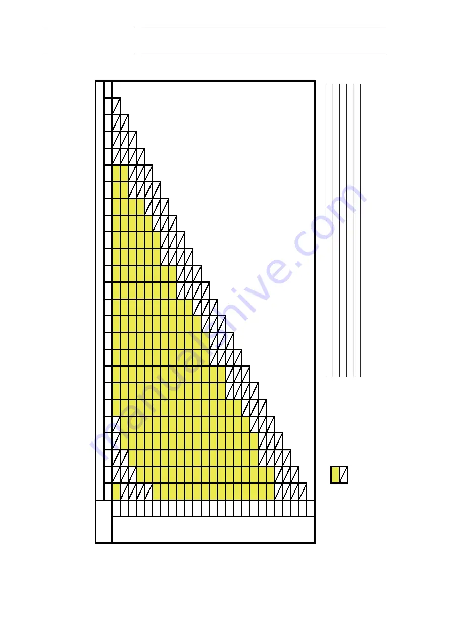
Table 5-3: Settable Angle for S-Axis Stopper
180
165
150
135
120
105
90
75
60
45
30
15
0
-15
-30
-45
-60
-75
-90
-105
-120
-135
-150
-165
-180
-180
-165
-150
-135
-120
-105
-90
-75
-60
-45
-30
-15
0
15
30
45
60
75
90
105
120
135
150
165
180
: Settable angle
: Disabled angle
+ Direction Angles
- Direction Angles
This table can be used when installing two mechanical stoppers on the S-axis.
The vertical axis of the table shows the angles in the positive direction, and the horizontal axis of the table
shows the angles in the negative direction.
For example, if one stopper is to be installed at a 180 degree angle in the positive direction, the other one
can be installed within the range of +/-105 degree angles: since more than 60 degrees of interval is required
to mount two stoppers, the chart indicates that the other angles are inappropriate for the installation.
Exception: The top left cell indicates the mountability of one stopper.
38 of 100


