4-13
162068-1CD
162068-1CD
MH-SERIES
POSITIONER
4 Installation
4.4 Tailstock Column Installation
5. To find the
X value
in the tailstock mounting formula for the drive
assembly, locate the drive assembly model name in
4.4.2
Type II Installation
To install the tailstock of a Type II assembly onto a cell base or floor,
proceed as follows:
1. Ensure the proper position for the headstock assembly per system
layout. The headstock must permanently anchored to the floor/base.
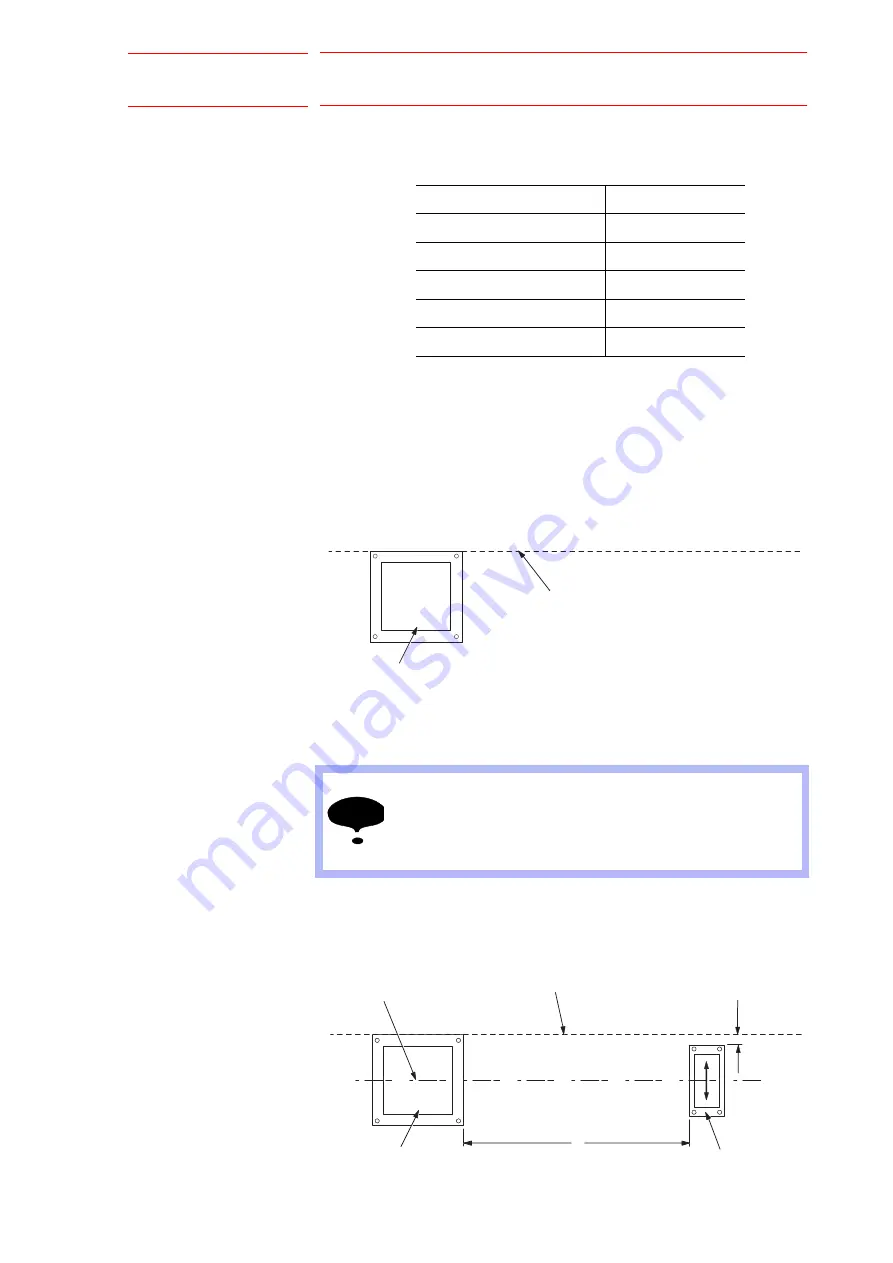
2. Using a carpenter’s chalk string, strike a chalk line on the floor from
the edge of the headstock base towards location of the tailstock.
Fig. 4-22: Strike Chalk Line
3. Position the tailstock on the floor across from the headstock.
4. Use the chalk line and the center line of each component as guides for
placement of the tailstock column on the floor.
5. To position the tailstock accurately on the bearing center line, make
two measurements from the tailstock base to the chalk line and adjust
the base as necessary.
Fig. 4-23: Tailstock Placement - Type II
Table 4-6: MotoMount Offset (X Value)
Type I System
X - value
MHT95 - mm
8
MHT180 - mm
8
MHT505 - mm
57
MHT1605 - mm
168
MHT3105 - mm
145
NOTE
Keeping the center line of each component aligned is not
critical. However, the closer the bearings of both
components are aligned with one another, the greater the
degree of misalignment allowed with other system
components.
CHALKLINE
HEADSTOCK
COLUMN BASE
CHALK LINE
225 MM
(8.85 IN.)
TAILSTOCK
RISER BASE
D
HEADSTOCK/TAILSTOCK
BEARING CENTERLINE
39/101


