4.4 Start-Up Flowcharts
DAN G ER!
E le c tric a l S h o c k Hazard. D o n o t c o n n e c t o r d is c o n n e c t w irin g w hile the p o w e r is on. F ailure to c o m p ly w ill re s u lt in de a th or
s e rio u s injury. B e fo re s e rv ic in g , d is c o n n e c t a ll p o w e r to th e equipm en t. T h e in te rn a l c a p a c ito r re m a in s c h a rg e d e v e n a fte r th e p o w e r
s u p p ly is tu rn e d off. The c h a rg e in d ic a to r LE D w ill e x tin g u is h w h en the D C b u s volta ge is b e lo w 5 0 Vdc. To p re v e n t e le c tric shock, w ait
a t le a s t five m in u te s a fte r a ll in d ic a to rs are O F F a n d m e a s u re the D C bu s v olta ge le v e l to con firm s afe level.
Note: A lw ays perform m otor rotation direction setup prior to setting the encoder rotation direction.
♦ PG Encoder Setup
■ PG Encoder Resolution Setup
Set the encoder resolution (incremental signal in the case o f absolute encoders with Sin/Cos channels) in parameter F1-
01
.
■ PG Encoder Rotation Direction Setup
Perform the following steps to make sure the PG encoder rotation direction is set up correctly in the drive:
If information about the signal sequence of the PG encoder is available:
1. Check the sequence of PG encoder phases A and B when the motor drives the elevator in up direction.
2. If the PG encoder A phase leads phase B, make sure F1-05 is set to 0.
3. If the PG encoder B phase leads phase A, make sure F1-05 is set to 1.
If no information about the signal sequence of the PG encoder is available:
1. Turn the motor manually in elevator up direction while checking the value of monitor U1-05.
2. If the value in U1-05 is positive, the set PG encoder direction is correct.
3. If the value in U1-05 is negative, alter the setting of parameter F1-05.
Note: A lw ays set the m otor rotation direction prior to the encoder rotation direction. Refer to
M o to r R otation D ire c tio n Setup on
page 90.
♦ Digital Operator Display Unit Selection
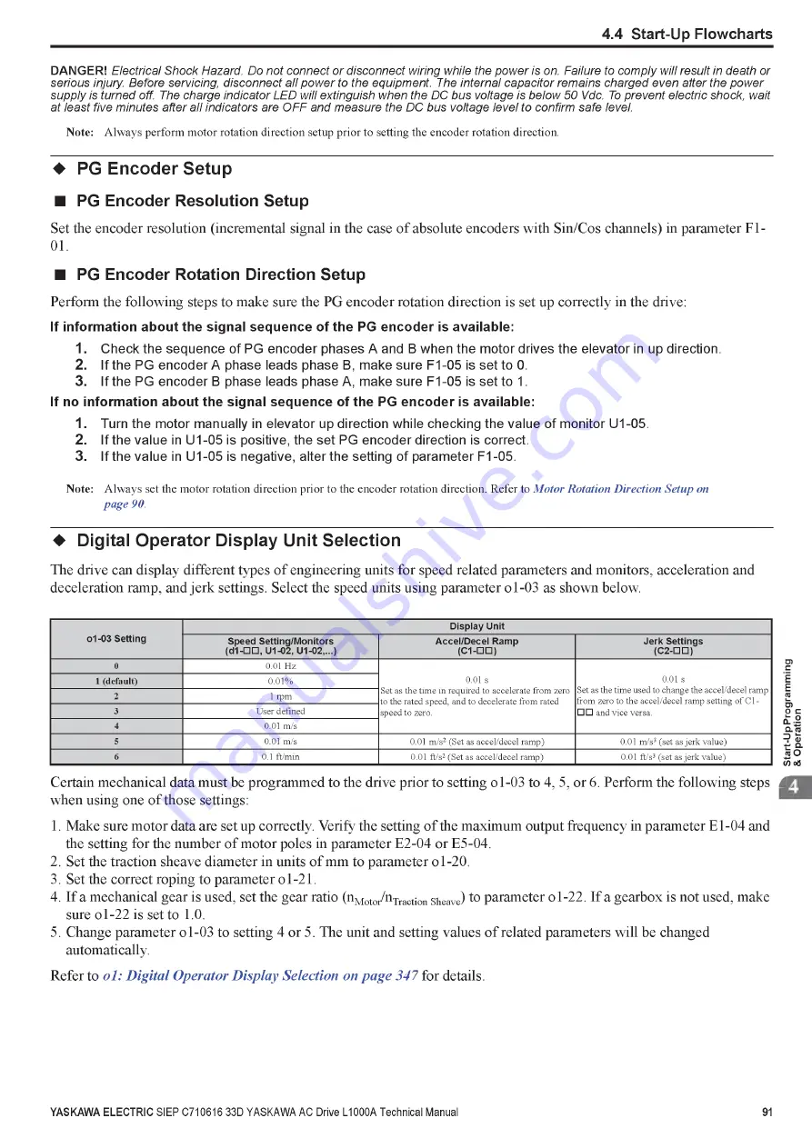
The drive can display different types of engineering units for speed related parameters and monitors, acceleration and
deceleration ramp, and jerk settings. Select the speed units using parameter o1-03 as shown below.
o1-03 Setting
Display Unit
Speed Setting/Monitors
( d l- п п , U1-02, U1-02,...)
Accel/Decel Ramp
(С 1-П П )
Jerk Settings
(С 2-П П )
0
0.01 Hz
0.01 s
Set as the tim e in required to accelerate from zero
to the rated speed, and to decelerate from rated
speed to zero.
0.01 s
Set as the time used to change the accel/decel ramp
from zero to the accel/decel ramp setting o f C1-
□ □ and vic e versa.
1 (default)
0.01%
2
1 rpm
3
User defined
4
0.01 m/s
5
0.01 m/s
0.01 m /s2 (Set as accel/decel ramp)
0.01 m /s3 (set as jerk value)
6
0.1 ft/min
0.01 ft/s2 (Set as accel/decel ramp)
0.01 ft/s3 (set as jerk value)
Certain mechanical data must be programmed to the drive prior to setting o1-03 to 4, 5, or 6 . Perform the following steps
Y
4
when using one o f those settings:
1. Make sure motor data are set up correctly. Verify the setting of the maximum output frequency in parameter E1-04 and
the setting for the number o f motor poles in parameter E2-04 or E5-04.
2. Set the traction sheave diameter in units of mm to parameter o1-20.
3. Set the correct roping to parameter o1-21.
4. If a mechanical gear is used, set the gear ratio (nMotor/nTraction Sheave) to parameter o1-22. If a gearbox is not used, make
sure o 1-22 is set to 1.0 .
5. Change parameter o1-03 to setting 4 or 5. The unit and setting values o f related parameters will be changed
automatically.
Refer to
o1: Digital Operator Display Selection on page 347
for details.
YASKAWA ELECTRIC SIEP C710616 33D YASKAWA AC Drive L1000A Technical Manual
91
St
art
-U
p
P
ro
g
ra
m
m
in
g
&
O
p
e
ra
ti
o
n


