5-35
A.
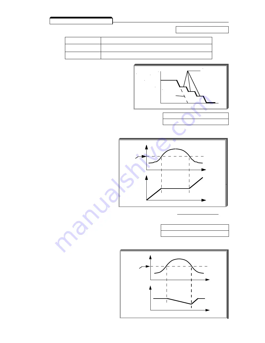
n092 : Stall Prevention During Deceleration
Factory setting: 0
Setting
Function
0
Stall prevention during deceleration enabled
1
Stall prevention during deceleration disabled
Stall prevention during deceleration
automatically adjusts the deceleration rate
while monitoring the DC bus voltage to
prevent overvoltage during deceleration.
When the motor load is large or decel
time is short, actual decel time may be longer
than the set value because of stall prevention.
B.
n093 : Stall Prevention Level During
Factory setting: See Table A3-1
Acceleration
Range: 30 - 200 %
This parameter determines the actual Drive output current level during an acceleration condition.
Set in percent of Drive rated output current.
A setting of " 200 " disables stall
prevention during acceleration.
During acceleration, if the output
current exceeds the value in n093 ,
acceleration stops and frequency is
maintained. When the output current
goes below the value set in n093 ,
acceleration resumes.
In the constant horsepower region
[actual output frequency
≥
max.
voltage frequency (n013 )], the stall
prevention level during acceleration is
changed by the following formula:
Stall prevention level during
= Stall prevention level during accel x
Max. voltage frequency
accel (constant horsepower)
Actual output frequency
5.23 STALL PREVENTION
TIME
FREQUENCY
SET
DECEL
TIME
Controls the
deceleration
time needed to
prevent over-
voltage fault.
C.
n094 : Stall Prevention Level At Set Speed
Factory setting: 160%
Range: 30 - 200 %
This parameter determines the actual Drive output current level while operating at set speed
(frequency). Set in percent of Drive rated output current (see Appendix 2).
A setting of " 200 " disables stall
prevention at set speed. During
running at set speed, if the output
current exceeds the value set in n094
, the drive will begin to decelerate.
When the output current goes below
the value set in n094 , acceleration
begins, up to the set frequency.
t
t
MOTOR
CURRENT
OUTPUT
FREQ.
Constant
n074
setting
Parameter
n094
Setting
t
t
MOTOR
CURRENT
OUTPUT
FREQ.
Constant
n073
setting
Parameter
n093
Setting
Summary of Contents for GPD315/V7-4X
Page 1: ...GPD 315 V7 and V7 4X Technical Manual...
Page 4: ......
Page 20: ...xvi...
Page 22: ......
Page 40: ...1 18...
Page 52: ...3 2...
Page 56: ...4 4...
Page 101: ...5 45 PID Block Diagram...
Page 130: ...A1 8...
Page 134: ...A3 2...
Page 136: ...A4 2...
Page 146: ...A6 6...
Page 150: ...A7 4...
Page 154: ...A8 4...
Page 158: ......
Page 160: ......


