5.4 Fault Detection
YASKAWA ELECTRIC
TOEP C710687 02B FSDrive-MV1000 Instructions
159
T
ro
ubles
hoo
ting
5
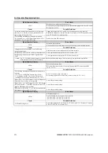
Digital Operator Display
Fault Name
PGo
PG Disconnect (for Control Mode with PG)
No PG pulses are received for longer than the time set to F1-14.
Cause
Possible Solutions
PG cable is disconnected.
Reconnect the cable.
PG cable wiring is incorrect.
Correct the wiring.
PG has no power.
Check the power line to the PG encoder.
PG encoder brake is clamped shut.
Ensure the motor brake releases properly.
Digital Operator Display
Fault Name
PGoH
PG Hardware Fault (detected when using a PG-X3 option card)
PG cable is not connected properly.
Cause
Possible Solutions
PG cable is disconnected.
Reconnect the cable.
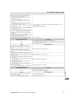
Digital Operator Display
Fault Name
SEr
Too Many Speed Search Restarts
The number of Speed Search restarts exceeded the number set to b3-19.
Cause
Possible Solutions
Speed Search parameters are set to the wrong
values.
• Reduce the detection compensation gain during Speed Search (b3-10).
• Increase the current level when attempting Speed Search (b3-17).
• Increase the detection time during Speed Search (b3-18).
• Repeat Auto-Tuning.
Digital Operator Display
Fault Name
SYNC
Commercial Synchronous Switching Error
An error was detected during commercial synchronous switching. (The synchronous switching
signal is ON)
Cause
Possible Solutions
The drive input main circuit voltage (frequency)
is not detected correctly.
• Check the main circuit wiring and input voltage detection circuit on the drive side.
• Connect the drive-side main circuit wiring correctly (positive phase).
Match the phase connected to the motor with a commercial power phase, with the drive input
and output phases.
• Replace the input voltage detection circuit.
Commercial synchronous switching is not
completed within the time limit (n7-76).
• Check that the switching command and switching answers are operating correctly.
• Review the command sequence to the switches.
Check the power state and load state if voltage synchronization is not achieved.
• Switch in a state with a small power fluctuation.
• Revise the run state to that the load fluctuation is reduced.
• Perform adjustment of the synchronization in the setting parameters (n7-
).
The switch performs an operation different from
the command (DO) from the drive.
• Check that the switching command and switching answers are operating correctly.
• Review the command sequence to the switches.
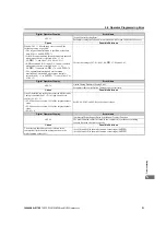
Digital Operator Display
Fault Name
TME
Transformer Temperature Fault
The temperature of the transformer has exceeded the protection level set to L8-87.
Cause
Possible Solutions
Cooling fan fault possibly due to inadequate
cooling airflow
If the cooling airflow is inadequate, replace the cooling fan.
The intake filter is soiled.
Clean the intake filter.
Parameter setting error
Check the parameter settings.
Thermistor fault and disconnected signal line
If the problem occurs even at a low temperature, for example immediately after switching on the
power, contact Yaskawa or your nearest sales representative.
Digital Operator Display
Fault Name
TME1
Transformer Temperature Fault 1
The temperature of the transformer has exceeded the temperature fault level.
Cause
Possible Solutions
Cooling fan fault possibly due to inadequate
cooling airflow.
If the cooling airflow is inadequate, replace the cooling fan.
The intake filter is soiled.
Clean the intake filter.
Parameter setting error
Check the parameter settings.
Thermistor fault and disconnected signal line
If the problem occurs at a low temperature, for example immediately after applying power,
contact Yaskawa or your nearest sales representative.
Summary of Contents for FSDrive-MV1000 Series
Page 8: ...8 YASKAWA ELECTRIC TOEP C710687 02B FSDrive MV1000 Instructions...
Page 106: ...3 9 Wiring Check 106 YASKAWA ELECTRIC TOEP C710687 02B FSDrive MV1000 Instructions...
Page 210: ...6 7 Spare Parts 210 YASKAWA ELECTRIC TOEP C710687 02B FSDrive MV1000 Instructions...
Page 222: ...B 1 European Standards 222 YASKAWA ELECTRIC TOEP C710687 02B FSDrive MV1000 Instructions...


