background image

12

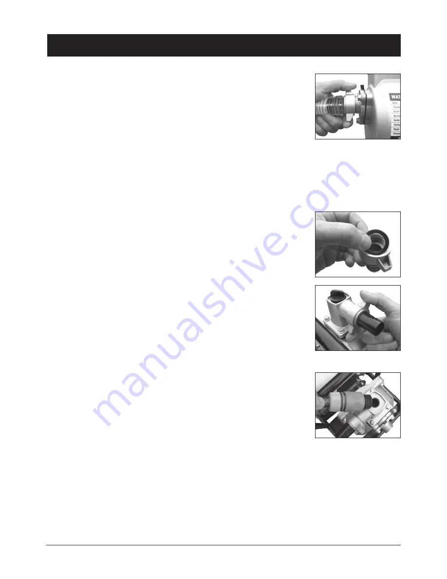
6.   Align and screw the collar onto the thread of the suction inlet (8) port of the  

pump (Fig. 5).

Note:

 Ensure the collar is tightly fastened onto the suction inlet (8); failure to do so 

may result in an air leak.

Discharge Outlet
Connecting Hose or Pipe to the Discharge outlet (not included)
Note: 

Keep all hoses short and as straight as possible, failure to do so may decrease the pumps performance.

Caution: 

All connections must be air tight, failure to do so may result in an air leak which can prevent the pump 

from priming. It is recommended that a thread sealant (not included) and/or Teflon tape (not included) is used on 
threads to ensure a water tight seal and prevent any leakage.
1.   Insert a hose adapter (24) into one of the collars (22).

Note:

 Ensure that an o-ring (21) is fitted into the collar (22) (Fig. 6), failure to do so 

may result in an air leak.
2.   Add thread sealant (not included) and/or Teflon tape (not included) on to the 

discharge outlet (9).

3.  Align and screw the collar onto the thread of the discharge outlet (9) port of the 

pump (Fig. 7).

Note:

 Ensure the collar is tightly fastened onto the discharge outlet (9); failure to do so 

may result in an air leak.

Priming

Priming the pump prepares the motor for safe operation.

Caution:

 Do not run the pump dry, this may result in damage to the pump.

1.   Unscrew the priming cap (11) by turning anti-clockwise. Using a hose, fill the pump 

by pouring water into the priming plug hole (Fig. 8).

2.   Ensure that the pump and suction line are full.
3.   Replace the priming cap (11) and ensure it is secure.
4.   Fully open any shut off mechanisms (eg: spray nozzle, valves etc.) in the input and output hose or pipe so that 

the air can escape without obstruction.

SETUP & INSTALLATION (cont.)

Fig. 5

Fig. 7

Fig. 8

Fig. 6

Summary of Contents for YW20PTP

Page 1: ...2 Stroke Petrol Transfer Pump Model YW20PTP 1013...

Page 2: ...S 4 KNOW YOUR PRODUCT 5 PACK CONTENTS 8 DESCRIPTION OF SYMBOLS 8 GENERAL SAFETY INSTRUCTIONS 9 ADDITIONAL SAFETY INSTRUCTIONS FOR PUMPS 10 SET UP INSTALLATION 11 OPERATION 13 MAINTENANCE 16 SPARE PART...

Page 3: ...3...

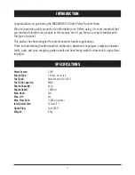
Page 4: ...ous water transfer applications These include draining flooded laundries bathrooms basements or garages emptying rainwater tanks pools and spas emptying garden ponds and transferring water for domesti...

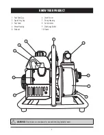
Page 5: ...CT 1 Fuel Tank Cap 2 Spark Plug Cap 3 Fuel Tank 4 Motor Housing 5 Exhaust 6 Drain Screw 7 Pump Housing 8 Suction Inlet 9 Discharge Outlet 10 Frame 1 3 10 8 WARNING This product is not suitable for use...

Page 6: ...6 KNOW YOUR PRODUCT cont 11 12 16 15 13 14 17 11 Priming Cap 12 Throttle Lever 13 Air Filter 14 Fuel Lever 15 Choke Lever 16 Recoil Starter 17 Engine Kill Button...

Page 7: ...g Socket Wrench Screwdriver 19 8 x10 Open Spanner 20 Fuel Mixing Bottle 21 Flat O Ring x2 22 Collar x2 23 Hose Clamp x3 24 Hose Adaptor x2 25 Filter Strainer Assembly KNOW YOUR PRODUCT cont 18 19 20 2...

Page 8: ...ssembly 2 x Flat O Ring 2 x Collar 2 x Hose Adaptor 1 x Instruction Manual Hp min no l kW p hr Read instruction manual Per hour Revolutions or reciprocation per minute Horse power No load speed kiloWa...

Page 9: ...mes Proper footing and balance enables better control of the pump in unexpected situations d Use safety equipment Always wear eye protection Dust mask non skid safety shoes and hard hat must be used f...

Page 10: ...The muffler becomes very hot during operation and remains hot for a while after stopping the engine Exhaust may contain chemicals that may cause cancer or reproductive harm This appliance is not inten...

Page 11: ...ne to prevent the pipe from collapsing due to pressure from suction Caution All connections require being air tight failure to do so can result in an air leak which can prevent the pump from priming I...

Page 12: ...ng 21 is fitted into the collar 22 Fig 6 failure to do so may result in an air leak 2 Add thread sealant not included and or Teflon tape not included on to the discharge outlet 9 3 Align and screw the...

Page 13: ...plug cap 2 Pre Operation Inspections Air Filter The air filter 13 must always be in perfect working order to prevent debris and dust from being sucked into the engine thus reducing the efficiency and...

Page 14: ...efer to the specs of the spark plug manufacture To remove install and inspect the spark plug refer to the maintenance section of this instruction manual page 16 Starting the Engine 1 Turn the fuel lev...

Page 15: ...discharge outlet 1 To increase the speed of the engine and water flow move the throttle lever 12 upwards towards the H indicator Fig 14 2 To decrease the speed of the engine and water flow move the th...

Page 16: ...st be intact and clean if not either clean or replace the filter 3 Replace the filter filter cover and nut Removing installing and inspecting the spark plug 1 Remove the spark plug cap 2 2 Remove the...

Page 17: ...e Check Fuel Tank Adjust inlet and exhaust valves Recommended Check Maintenance Chart Item Inspect and tighten all nuts and bolts Air Filter Fuel Tank Nozzle Fuel lines Spark Plug Remove carbon in com...

Page 18: ...lve to on position Low quality or deteriorated old fuel oil mix Use only fresh 91 octane unleaded fuel oil mix Dirty muffler exhaust Check and clean Choke adjusted incorrectly Move choke lever to CLOS...

Reviews: