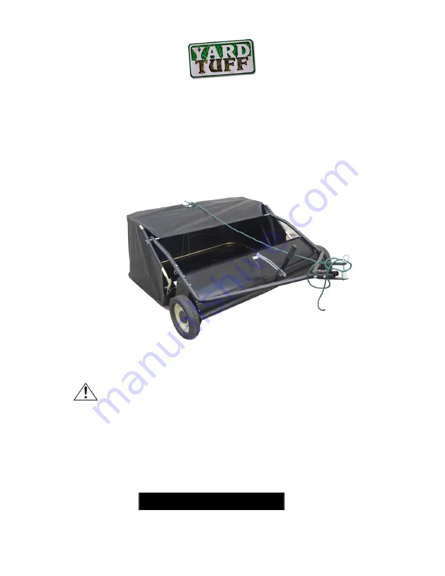
background image


48” Sweeper 

OWNER’S MANUAL 


WARNING:


Read carefully and understand all 

ASSEMBLY AND OPERATION INSTRUCTIONS


before operating. Failure to follow the safety rules and other basic safety 
precautions may result in serious personal injury. 


11022010

Item# SP-48 

Summary of Contents for SP-48

Page 1: ...L WARNING Read carefully and understand all ASSEMBLY AND OPERATION INSTRUCTIONS before operating Failure to follow the safety rules and other basic safety precautions may result in serious personal in...

Page 2: ...contacted us to determine if it can or should be performed on the product For technical questions please call 1 952 938 5222 TECHNICAL SPECIFICATIONS Item Description Hopper Capacity 14 5 Cubic Feet T...

Page 3: ...fety apparel and equipment Use safety goggles or safety glasses with side shields which comply with current national standards or when needed a face shield Use as dust mask in dusty work conditions Th...

Page 4: ...ght 5 Hitch Bracket 6 Sweeper Housing Assembly 7 Front Support Rod 8 Bag Arm Tube 2 9 Bag Frame Strap 10 Hopper Support Rod 2 11 Lower Hopper Side Tube Right 12 Lower Hopper Side Tube Left 13 Upper Ho...

Page 5: ...t M8x55 Hex Bolt M8x40 Hex Bolt M6x40 Hex Bolt M8x20 Hex Bolt M8x16 Nylon Lock Nut M8 Nylon Lock Nut M6 Hex Bolt M6x12 Big Flat Washer 8 K L M N O P Q R Y Z 1 1 2 5 4 2 2 2 1 4 Angle Bracket Adjustabl...

Page 6: ...H and left hand L H are determined from the operator s position while seated on the tractor Figure 1 Assemble the angle bracket to the sweeper housing using a M8 16 hex bolt F and a Nylon Lock Nut M8...

Page 7: ...itch brackets to the hitch tubes using two M8 x 55 hex bolts B and M8 nylon lock nuts G The bolts should straddle the front hitch tube bolt Do not tighten yet At this time tighten the four bolts faste...

Page 8: ...own in figure 6 Use two M8 40 hex bolts C and M8 Nylon Lock nut G Do not tighten yet Figure 7 Insert a M8 20 hex bolt E through the angle bracket Assemble onto the bolt in order the adjustable polo sp...

Page 9: ...uring the height adjustment handle Figure 8 Insert the carriage bolt M8 30 through the height adjustment handle Assemble onto the bolt in order the bolt the height adjustment handle the wear washer th...

Page 10: ...lide the tube through the two loops sewn to the top rear seam inside the hopper bag Figure 11 Insert the two upper hopper side tubes through the stitched flaps on each side of the hopper bag Figure 11...

Page 11: ...ube onto the ends of the lower hopper side tubes Fasten together using plastic plugs Figure 13 Place the assembled lower hopper tubes into the bottom of the hopper bag Figure 13 Attach the ends of the...

Page 12: ...front edge of the bag bottom Figure 14 Assemble the bag frame strap to the lower hopper side tubes using two 6x37 clevis pins Q and 2 R pins O Figure 15 Secure the bag corners around the lower hopper...

Page 13: ...Tip the hopper onto its back to assemble the two hopper support rods Place the ends of each rod into the upper and lower rear hopper tubes bending the rod just enough to fit into the holes in the tube...

Page 14: ...ope to the top center of the hopper bag frame Figure 19 To assemble the hopper bag to the sweeper slide the ends of the bag arm tubes into the ends of the sweeper s hitch tubes and secure with two 6 4...

Page 15: ...hitch brackets to the tractor hitch arranging the 3 4 spacers so that the bottom of the sweeper bag is approximately level and 5 to 7 above the ground See figure 21 for tractor hitches that are 10 to...

Page 16: ...Page of 20 16 22 21...

Page 17: ...ing the sweeper MAINTENANCE Maintain your sweeper It is recommended that the general condition of any sweeper be examined before it is used Keep your sweeper in good repair by adopting a program of co...

Page 18: ...Page of 20 18 DIAGRAM PARTS LIST...

Page 19: ...racket 1 17 Inside Star Washer 2 56 Hitch Bracket Straight 1 18 Dust Cover Retainer 2 57 Height Adjustment Handle 1 19 Brush Shaft Bushing 2 58 Bag Arm Tube 2 20 Brush Shaft 1 59 Front Support Rod 1 2...

Page 20: ...Page of 20 20 WARRANTY One year limited warranty TG PO BOX 202 Hopkins MN 55343 Made in China...

Reviews: