20 | RMB/ENERGIE GmbH
assembly
Operation manual CHP 5.0 - 30.0 | Status 01.2020
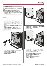
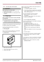
5.3.4 Screwing the control cabinet in position
A
Open the control cabinet.
A
Mark the drill hole positions on the wall.
A
Drill the holes for the screws.
A
Screw the control cabinet onto the wall.
A
Observe the minimum distances.
D
“5.2.2 Installation room” (page 15).
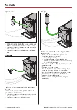
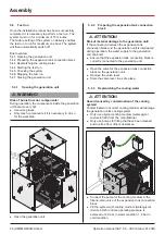
5.3.5 Screwing the expansion tank connection
block in position
A
Mark the drill hole positions on the wall.
A
Drill the holes for the screws.
A
Screw the expansion tank connection block onto the
wall.
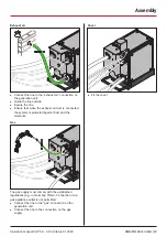
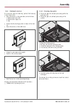
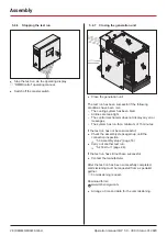
5.3.6 Connecting the generation unit
When connecting the system to the heating system it is
necessary to follow the appropriate hydraulic diagram.
D
“12.2 Hydraulic diagrams” (page 35).
Always match the connections to the identifiers on the
generation unit.
Pay attention the to connection sizes and type when
connecting the lines.
Generation unit connection sizes
Connection
Connection size and type
CHP
5.0 - 7.2
CHP
11.0 - 20.0
CHP
25.0 - 30.0
Buffer water
return line
1” male
thread
1” male
thread
1” male
thread
Buffer water
supply line
1” male
thread
1” male
thread
1” male
thread
Expansion
tank
3/4” male
thread
3/4” male
thread
3/4” male
thread
Condensate
3/4” male
thread
3/4” male
thread
3/4” male
thread
Flue gas
DN 80
DN 80
DN 80
Exhaust air
DN 100
DN 100
DN 160
Gas
1/2” female
thread
1/2” female
thread
1” male
thread
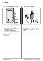
A
Remove the cover.
If necessary, the entire rear cover can be released and
removed.

