background image

1-6

1. SAFETY PRECAUTIONS

CL600 Operator's Manual

10. Always wear protective goggles and gloves when 

servicing or repairing the tractor or the loader. 

11. When servicing or replacing pins in cylinder ends, 

bucket, etc., always use a brass drift and 
hammer. Failure to observe the preceding 
practice can result in injury from flying metal 
fragments.

12. Do not remove the loader from the tractor without 

an approved bucket support.

13. Use only Yanmar genuine parts to prevent the 

result of severe accidents.

14. To prevent serious injury or death, assemble, 

remove and install the loader as explained in the 

Operator's Manual

.

Stored loader and attachments can fall and cause 
serious injury or death. Securely support the loader 
and attachments to prevent from falling.

1. Detach the loader or attachments on a solid and 

level ground.

2. Keep a child and bystanders away from stored 

loader and attachments.

3. Loader frame must be equipped with bucket or 

attachment to provide necessary balance for 
storage.

4. Do not loosen hydraulic fittings or hoses while 

storing the loader.

5. Do not climb or lean on the loader stored on 

stand.

The rubber products have a deteriorative character. 
The deteriorated rubber product may cause such as 
fluid leakage, fire, burn injury.

Safety Alert Symbol

The loader safety decals illustrated in this section are 
provided in critical areas on the loader so that people 
including the operator can always remain aware of 
potential hazards. The loader safety decals contain 
the words DANGER, WARNING and CAUTION 
together with the safety alert symbol. DANGER and 
WARNING stand for the most serious hazards. The 

Operator's Manual 

also contains special safety 

messages that explain potential hazards about which 
the operator must remain cautious. The messages 
are presented together with the word CAUTION and 
the safety alert symbol.

Care of DANGER, WARNING and 
CAUTION Decals

1. Always keep all the DANGER, WARNING and 

CAUTION decals clean and clearly legible.

2. Clean the DANGER, WARNING and CAUTION 

decals with soap and water, and wipe dry with 
clean soft cloth.

3. Replace damaged or missing DANGER, 

WARNING and CAUTION decals with new 
decals available from YOUR LOCAL YANMAR 
TRACTOR DEALER.

4. If a component that has DANGER, WARNING 

and CAUTION decals is replaced with a new 
decal, ensure that the new decal is on the same 
location as on the replaced component.

5. Make sure the new DANGER, WARNING and 

CAUTION decals are smoothly affixed on a clean 
and dry surface. Squeeze out trapped air.

6. Safe Practices for Storing the Loader

7. Change the Rubber Products, such as Hydraulic Hose, for Every 2 Years

8. Understand the Tractor and the Loader Safety Decals

Summary of Contents for CL Series

Page 1: ...national Pkwy Adairsville GA 30103 http www yanmar com OPERATOR S MANUAL CL Series CL600 LOADER for Lx410 450 490 Version 1 0 Code No 0A052 U00601 ENGLISH Yanmar America Corporation 101 International...

Page 2: ...Operator s Record Owner s Name Owner s Address Owner s Phone Number Dealer Seller Name Dealer Seller Address Dealer Seller Phone Number NOTE...

Page 3: ...ly The Operator s Manual is organized with sections arranged in a particular order so that the operator can better understand the safety messages and the controls on the tractor and the loader to help...

Page 4: ...ars 1 6 8 Understand the Tractor and the Loader Safety Decals 1 6 Safety Alert Symbol 1 6 Care of DANGER WARNING and CAUTION Decals 1 6 Decals Location 1 7 1 Specifications Table 3 1 1 Overview 4 1 2...

Page 5: ...e 7 1 Tightening Torque 7 1 Check the Hydraulic Hoses 7 1 2 First 10 Hours 7 1 Tighten the Loader Mount Bolt 7 1 3 Every 50 Hours 7 2 Check the Loader Mount Bolt Tightening Torque 7 2 Check the Hydrau...

Page 6: ...tor s safety is involved Please read and strictly observe the message that follows the safety alert symbol DANGER WARNING CAUTION NOTICE WARNING READ AND FOLLOW ALL INSTRUCTIONS IN THE OPERATOR S MANU...

Page 7: ...itional protection including non slip safety boots or shoes protective goggles and gloves etc as appropriate or required by applicable local laws and regulations Wear ear protection in a noisy environ...

Page 8: ...l lighting and marking requirements 14 Consult local utilities before beginning work Know the location of and avoid contact with all underground cables pipelines overhead wires and other hazards in th...

Page 9: ...o not under any circumstances lift the loader higher than necessary to clear the ground Always carry loads low to the ground 4 Move slowly and carefully Avoid rough terrain 5 Operate on Slopes Incline...

Page 10: ...ff the engine Remove the key from the starter key switch 1 Do not walk or work under a raised loader bucket or attachment unless the preceding component is securely supported and held in a stable posi...

Page 11: ...ge fire burn injury Safety Alert Symbol The loader safety decals illustrated in this section are provided in critical areas on the loader so that people including the operator can always remain aware...

Page 12: ...s seat only Lock pins must be installed and secured before operation When parking choose flat and hard ground Lower the bucket to the ground set brakes before leaving tractor Before disconnecting hyd...

Page 13: ...arms should be at low position during transport of tractor Do not transport or move round or square bales with the bucket TO AVOID SERIOUS INJURY OR DEATH CAUSED BY FALLING LOADS Load on raised bucke...

Page 14: ...Before operating the loader always verify the following on both the right and left sides of the unit Both hooks must be inserted into the V groove on the bucket side Both handles must be situated in t...

Page 15: ...EALER for technical assistance When ordering a part component let YOUR LOCAL YANMAR TRACTOR DEALER know the loader serial number Find the serial number and enter the serial number in the following tab...

Page 16: ...in mm 29 9 760 D Maximum Dump Angle degree 45 E Reach with Bucket on Ground in mm 74 3 1886 F Maximum Rollback Angle degree 40 G Digging Depth in mm 7 5 190 Rising Time to Full Height w o Load sec 4...

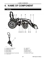
Page 17: ...ent control lever 3 Mast assembly 4 Boom assembly 5 Bucket cylinder 6 Quick hitch assembly latch pin handles 7 Loader bucket 8 Loader stand 9 Indicator 10 Boom lift cylinder 11 Loader mount 12 Mast mo...

Page 18: ...ch assembly latch pin handles Use to lock and unlock the loader bucket 7 Loader bucket The loader bucket is for scooping carrying and dumping the load 8 Loader stand Use the loader stand to support th...

Page 19: ...nd the right loader mounts 12 Mast mounting pin Use the mast mounting pins to secure the mast assembly to the loader mounts 13 Hydraulic quick couplers Use the hydraulic quick couplers to connect the...

Page 20: ...t are in good condition Do not under any circumstances operate the loader without first installing and raising the Roll Over Protective Structure ROPS Do not under any circumstances operate the loader...

Page 21: ...us personal injury or death In order to ensure the safety of the operator and the stability of the tractor always use Ballast Box BB200 as follows Condition Required 3 Point Hitch approximate Weight l...

Page 22: ...r 495 lb 225 kg 583 lb 265 kg IMPORTANT Avoid damage Avoid exceeding the maximum load ratings indicated on the tires Always fill the tire with the liquid above the rim level to prevent corrosion avoid...

Page 23: ...the loader bucket at the float position right dumps the loader bucket rearward raises the loader boom left curl the loader bucket IMPORTANT Avoid damage Do not attempt to operate the tractor at high s...

Page 24: ...h lines 3 and 4 Allow the transmission hydraulic oil to flow back and forth between the lines The implement control lever may be left in the float position Use the Implement Control Lever Lock The fol...

Page 25: ...figure below of the bucket during load lifting to prevent load spillage P1100362_2 eps a A b P5 3 top view_1 INCORRECT CORRECT 2022022 eps NOTE Do not be concerned if the bucket is not completely fill...

Page 26: ...ssible to avoid tipping over The preceding action is particularly relevant when a wheel drops into a rut Avoid injury or death from roll over accidents Move and turn the tractor at low speeds Watch fo...

Page 27: ...ing of surface material with the stockpile material The float position reduces the chance of surface gouging when removing snow or other similar materials 2021713 FLOAT SURFACE MATERIAL 2021713 202203...

Page 28: ...h Make additional passes until the desired depth is reached During each pass use the implement control lever to control the bucket position while at the working depth The preceding practice allows the...

Page 29: ...at right angles to the ditch Take a bite as big as the tractor can handle without lugging down Leave dirt which drifts over the side of the bucket for a final clean up Pile dirt on the high side for e...

Page 30: ...is a danger of the tractor rolling over or upending The object can also fall off or slide down along the boom and hit the operator When performing any of the operations described above always move and...

Page 31: ...or s Manual A Transmission hydraulic oil filler cap B Dipstick Check the Wheel Bolt Tightening Torque When a tire is replaced and the tire tread width is adjusted ensure at the following intervals tha...

Page 32: ...ing to start or operate the loader Failure to complete the operations can result in personal injury and can shorten the service life of the tractor the loader and the components 1 Check all the compon...

Page 33: ...icult to see always use a piece of cardboard or wood to protect body parts when searching for leaks do not under any circumstances use hands or any body part to detect pressurized oil leaks use a magn...

Page 34: ...in contact with the ground Dump the bucket until the tip of the bucket C rests on the ground 15 Continue dumping the bucket until the front wheels are slightly off the ground 16 Shut off the engine 17...

Page 35: ...ough the hydraulic quick couplers A 23 Place the hoses above the right section of the boom A Hydraulic quick couplers 1 Store the loader in a clean dry location preferably indoors Make sure that the l...

Page 36: ...ucket 12 As necessary lift or lower the boom until the mast fulcrum B of the mast assemblies engages the pivot C located on the loader mounts A Implement control lever B Mast fulcrum mast assembly C P...

Page 37: ...ucket A Saddle of attachment B Mounting plate of quick hitch assembly Make sure that the mounting plate of quick hitch assembly is seated securely in the bucket saddle and that the bucket saddle is in...

Page 38: ...addle 9 Slowly move back the tractor away from the dismounted bucket Maintenance An over center latch system is used to secure bucket to the quick hitch assembly Always keep the parts of the system cl...

Page 39: ...ed in the hydraulic system operate the implement control lever several times to bleed air Check whether there is air leak in pump inlet line contact YOUR LOCAL YANMAR TRACTOR DEALER 2 Loader rises too...

Page 40: ...ether the hydraulic fittings or hoses are worn out or damage contact YOUR LOCAL YANMAR TRACTOR DEALER Check whether the hydraulic fittings or hoses are connected properly connect the hydraulic fitting...

Page 41: ...whether the hydraulic cylinder seals are worn out or damaged replace hydraulic cylinder seals 2 A problem other than 1 above 2 Other problems Check whether the implement control valve is worn out or d...

Page 42: ...to the location of the overhead lift Carefully remove all the components from the shipping pallet Make sure that all the components listed in 2 Kit Contents below are in the assembly area and easily...

Page 43: ...ge nut for Front grille 58 to 72 78 to 98 3 BOLT 16 45 16 Flange bolt 16 45 mm L 1 7 in 224 253 304 343 4 BOLT 16 80 4 Flange bolt M16 80 mm L 3 1 in 224 253 304 343 5 BRACKET R CMP 1 Loader mount R 6...

Page 44: ...s close enough to connect the hoses to the hydraulic quick couplers on the tractor 4 c Connect the loader hoses to the hydraulic quick couplers on the tractor A Loader B Overhead lift C Plug tractor s...

Page 45: ...is engaged to the loader mount s pivot F E Mast fulcrum F Loader mount s pivot 4 f Make sure that the mast fulcrum does not slip out move the implement control lever to the Lower position The precedin...

Page 46: ...NOTE...
Page 47: ...Operator s Record Owner s Name Owner s Address Owner s Phone Number Dealer Seller Name Dealer Seller Address Dealer Seller Phone Number NOTE...

Page 48: ...national Pkwy Adairsville GA 30103 http www yanmar com OPERATOR S MANUAL CL Series CL600 LOADER for Lx410 450 490 Version 1 0 Code No 0A052 U00601 ENGLISH Yanmar America Corporation 101 International...

Reviews: