background image

PERIODIC MAINTENANCE

3TNV88F Service Manual

5-7

Periodic Maintenance Procedures

PERIODIC MAINTENANCE 
PROCEDURES

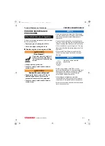
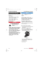
Perform the following maintenance after the initial 
50 hours of operation.

• Replace engine oil and engine oil filter

• Check and adjust cooling fan V-belt

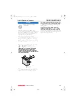
Replace engine oil and engine oil filter

WARNING

Burn Hazard!

• If you must drain the engine oil 

while it is still hot, stay clear of 
the hot engine oil to avoid being 
burned. 

• Always wear eye protection. 

• Failure to comply could result in death or 

serious injury.

WARNING

Sudden Movement Hazard!

• Engaging the transmission or PTO at an 

elevated engine speed could result in 
unexpected movement of the equipment. 

• Failure to comply could result in death or 

serious injury.

NOTICE

• Only use the engine oil specified. Other engine 

oils may affect warranty coverage, cause internal 
engine components to seize and/or shorten 
engine life.

• Prevent dirt and debris from contaminating the 

engine oil. Carefully clean the oil cap/dipstick and 
the surrounding area before you remove the cap.

• Never mix different types of engine oil. This may 

adversely affect the lubricating properties of the 
engine oil.

• Never overfill. Overfilling may result in white 

exhaust smoke, engine overspeed or internal 
damage.

NOTICE

• Always be environmentally 

responsible. 

• Follow the guidelines of the EPA or other 

governmental agencies for the proper disposal of 
hazardous materials such as engine oil, diesel 
fuel and engine coolant. Consult the local 
authorities or reclamation facility.

• Never dispose of hazardous materials 

irresponsibly by dumping them into a sewer, on 
the ground, or into ground water or waterways.

• Failure to follow these procedures may seriously 

harm the environment.

After Initial 50 Hours of Operation

3TNV88F_SVM_A4.book  7 ページ  2012年7月26日 木曜日 午後6時4分

Summary of Contents for 3TNV88F

Page 1: ...3TNV88F INDUSTRIAL ENGINES SERVICE MANUAL INDUSTRIAL ENGINES 3TNV88F SERVICE MANUAL 0BTN4 G00400 PRINTED IN JAPAN ...

Page 2: ...vement We reserve the right to make any change at any time without notice YANMAR and are registered trademarks of YANMAR CO LTD in Japan the United States and or other countries All Rights Reserved No part of this publication may be reproduced or used in any form by any means graphic electronic or mechanical including photocopying recording taping or informa tion storage and retrieval systems with...

Page 3: ...ies 2 1 Safety 3 1 General Service Information 4 1 Periodic Maintenance 5 1 Engine 6 1 Fuel System 7 1 Cooling System 8 1 Lubrication System 9 1 Starter Motor 10 1 Alternator 11 1 Electronic Control System 12 1 Electric Wiring 13 1 Failure Diagnosis 14 1 3TNV88F_SVM_A4 book i ページ 2012年7月26日 木曜日 午後6時4分 ...

Page 4: ...TABLE OF CONTENTS ii TNV DI Service Manual This Page Intentionally Left Blank 3TNV88F_SVM_A4 book ii ページ 2012年7月26日 木曜日 午後6時4分 ...

Page 5: ...ions in this manual are for a typical engine some specifications and components may be different from your engine Refer to the documentation supplied by the optional equipment manufacturer for specific service instructions YANMAR products are continuously undergoing improvement This Service Manual might not address possible field modifications to the equipment Contact an authorized YANMAR industri...

Page 6: ...INTRODUCTION 1 2 3TNV88F Service Manual This Page Intentionally Left Blank 3TNV88F_SVM_A4 book 2 ページ 2012年7月26日 木曜日 午後6時4分 ...

Page 7: ...aler or Distributor 2 4 What YANMAR will Do 2 4 What is not Covered by this Warranty 2 4 Warranty Limitations 2 5 Warranty Modifications 2 5 Questions 2 5 Emission System Warranty 2 6 YANMAR Co Ltd Limited Emission Control System Warranty USA Only 2 6 Your Warranty Rights and Obligations 2 6 Manufacturer s Warranty Period 2 6 Warranty Coverage 2 7 Warranted Parts 2 7 Exclusions 2 8 Owner s Warrant...

Page 8: ...YANMAR WARRANTIES 2 2 3TNV88F Service Manual This Page Intentionally Left Blank 3TNV88F_SVM_A4 book 2 ページ 2012年7月26日 木曜日 午後6時4分 ...

Page 9: ...is provided for these specific parts only the cylinder block cylinder head crankshaft forging connecting rods flywheel flywheel housing camshaft timing gear and gear case The warranty period for both the standard limited warranty and the extended limited warranty by duration or operation hours begins on the date of delivery to the original retail purchaser and is valid only until the applicable wa...

Page 10: ... the YANMAR product covered by this warranty found to be defective in material and or workmanship Such repairs and or replacements will be made at a location designated by YANMAR at no cost to the purchaser for parts or labor What is not Covered by this Warranty This warranty does not cover parts affected by or damaged by any reason other than defective materials or workmanship including but not l...

Page 11: ...be brought within one 1 year after the cause of action accrues or it shall be barred Some states and countries do not allow certain limitations on warranties or for breach of warranties This warranty gives you specific legal rights and you may also have other rights which vary from state to state and country to country Limitations set forth in this paragraph shall not apply to the extent that they...

Page 12: ... no charge to you including diagnosis parts and labor Manufacturer s Warranty Period The model year 1998 or later certified and labeled non road compression ignition engines are warranted for the periods listed below If any emission related part on your engine is found to be defective during the applicable warranty period the part will be replaced by YANMAR If your engine is certified as And its m...

Page 13: ...anted part during the warranty period Any replacement part which is functionally identical to the original equipment part in all respects may be used in the maintenance or repair of your engine and shall not reduce YANMAR s warranty obligations Add on or modified parts that are not exempted may not be used The use of any non exempted add on or modified parts shall be grounds for disallowing a warr...

Page 14: ...cluding receipts covering maintenance on your non road compression ignition engine but YANMAR cannot deny warranty solely for the lack of receipts or for your failure to ensure the performance of all scheduled maintenance YANMAR may deny your warranty coverage of your non road compression ignition engine if a part has failed due to abuse neglect improper maintenance or unapproved modifications You...

Page 15: ...3TNV88F Service Manual 3 1 3TNV88F Service Manual Section 3 SAFETY Page Safety Statements 3 3 Safety Precautions 3 4 3TNV88F_SVM_A4 book 1 ページ 2012年7月26日 木曜日 午後6時4分 ...

Page 16: ...SAFETY 3 2 3TNV88F Service Manual This Page Intentionally Left Blank 3TNV88F_SVM_A4 book 2 ページ 2012年7月26日 木曜日 午後6時4分 ...

Page 17: ...t has a label attached to it make sure you order the new part and label at the same time DANGER DANGER indicates a hazardous situation which if not avoided will result in death or serious injury WARNING WARNING indicates a hazardous situation which if not avoided could result in death or serious injury CAUTION CAUTION indicates a hazardous situation which if not avoided could result in minor or mo...

Page 18: ...tain conditions When you remove any fuel system component to perform maintenance such as changing the fuel filter place an approved container under the opening to catch the fuel Never use a shop rag to catch the fuel Vapors from the rag are flammable and explosive Wipe up any spills immediately Wear eye protection The fuel system is under pressure and fuel could spray out when you remove any fuel ...

Page 19: ...ey switch to the ON position for 10 to 15 seconds or until the fuel coming out of the air bleed port is free of bubbles to allow the electric fuel pump to prime the system If the unit has a mechanical fuel pump operate the fuel priming pump several times until the fuel coming out of the air bleed port is free of bubbles Failure to comply will result in death or serious injury DANGER Crush Hazard W...

Page 20: ... as required by the task at hand Never wear jewelry unbuttoned cuffs ties or loose fitting clothing when you are working near moving rotating parts such as the cooling fan flywheel or PTO shaft Always tie back long hair when you are working near moving rotating parts such as a cooling fan flywheel or PTO shaft Never operate the engine while wearing a headset to listen to music or radio because it ...

Page 21: ...epair the damage Failure to comply could result in death or serious injury WARNING Shock Hazard Turn off the battery switch if equipped or disconnect the negative battery cable before servicing the electrical system Check the electrical harnesses for cracks abrasions and damaged or corroded connectors Always keep the connectors and terminals clean Failure to comply could result in death or serious...

Page 22: ... engine speed WARNING Be sure to use the E ECU in conjunction with the engines whose models or serial numbers are specified by YANMAR Other E ECU engine combinations than specified will void the engine warranty Improper use or misuse of the E ECU may result in death or serious injury due to an abrupt and unexpected increase in engine speed WARNING Replacing the fuel injection pump involves rewriti...

Page 23: ...replaced as an assembly CAUTION To refuel the engine oil refuel slowly after removing the dipstick and both caps If you refuel rapidly the oil intrusion to the intake occurs through the PCV valve of the valve cover It will result in an oil hammer at engine start which may cause damage to the engine NOTICE Only use diesel fuels recommended by YANMAR for the best engine performance to prevent engine...

Page 24: ...e rain NOTICE Observe the following environmental operating conditions to maintain engine performance and avoid premature engine wear The standard range of ambient temperatures for the normal operation of YANMAR engines is from 5 F 15 C to 113 F 45 C If the ambient temperature exceeds 113 F 45 C the engine may overheat and cause the engine oil to break down If the ambient temperature is below 5 F ...

Page 25: ... coolant NOTICE Never overfill the engine with engine oil Always keep the oil level between the upper and lower lines on the oil cap dipstick NOTICE For maximum engine life YANMAR recommends that when shutting the engine down you allow the engine to idle without load for five minutes This will allow the engine components that operate at high temperatures such as the turbocharger if equipped and ex...

Page 26: ...er to clean the engine NOTICE Never use high pressure water or compressed air at greater than 28 PSI 193 kPa 19686 mmAq or a wire brush to clean the radiator fins Radiator fins damage easily NOTICE Never attempt to adjust the low or high idle speed limit screw This may impair the safety and performance of the machine and shorten its life If the idle speed limit screws require adjustment see your a...

Page 27: ...pump must be replaced replace it as an assembly only Do not replace individual components NOTICE Do not loosen or remove the four bolts retaining the fuel injection pump drive gear to the fuel injection pump hub Do not disassemble the fuel injection pump drive gear from the hub Correct fuel injection timing will be very difficult or impossible to achieve NOTICE The starter motor can be damaged if ...

Page 28: ...adequate charging and shorten the belt life Use the specified belt NOTICE Agricultural or other chemicals especially those with a high sulfur content can adhere to the IC regulator This will corrode the conductor and result in battery over charging boiling and charging malfunctions Consult YANMAR before using the equipment in such an environment or the warranty is voided NOTICE Make sure that the ...

Page 29: ...charger or have it repaired by a qualified repair facility NOTICE Never attempt to modify the engine s design or safety features such as defeating the engine speed limit control or the diesel fuel injection quantity control Modifications may impair the engine s safety and performance characteristics and shorten the engine s life Any alterations to this engine may void its warranty Be sure to use Y...

Page 30: ...id the YANMAR Limited Warranty NOTICE Never use a steel wire brush to clean fuel injectors Damage to the nozzle and other components is likely to result NOTICE Allow the engine to warm up for at least five minutes and the idle speed of the engine to return to normal before engaging the transmission or any PTOs Engaging the transmission or PTO at an elevated engine speed could result in an unexpect...

Page 31: ...ide the couplers may cause corrosion resulting in malfunction of the E ECU Avoid plugging unplugging the connector more than approx 10 times Frequent plugging unplugging of the connector may cause contact failure of the connector pins resulting in malfunction of the E ECU Do not use the E ECU that has ever suffered drop impact NOTICE Never permit anyone to operate the engine or driven machine with...

Page 32: ...SAFETY 3 18 3TNV88F Service Manual Safety Precautions This Page Intentionally Left Blank 3TNV88F_SVM_A4 book 18 ページ 2012年7月26日 木曜日 午後6時4分 ...

Page 33: ...nents 4 7 Main Electronic Control Components and Features 4 8 Function of Cooling System Components 4 10 Diesel Fuel 4 11 Diesel Fuel Specifications 4 11 Filling The Fuel Tank 4 15 Priming the Fuel System 4 16 Engine Oil 4 17 Engine Oil Specifications 4 17 Engine Oil Viscosity 4 17 Checking Engine Oil 4 18 Adding Engine Oil 4 18 Engine Oil Capacity Typical 4 18 Engine Coolant 4 19 Engine Coolant S...

Page 34: ...of Model Number 4 22 Engine General Specifications 4 22 Principal Engine Specifications 4 23 Engine Service Standards 4 24 Tightening Torques for Standard Bolts and Nuts 4 25 Abbreviations and Symbols 4 27 Symbols 4 27 Unit Conversions 4 28 3TNV88F_SVM_A4 book 2 ページ 2012年7月26日 木曜日 午後6時4分 ...

Page 35: ...t 7 Side filler port engine oil 8 Engine oil cooler 9 Fuel injection pump 10 Engine oil filter 11 Intake manifold 12 Dipstick engine oil 13 Fuel filter 14 Fuel return to fuel tank 15 Fuel inlet 16 Top filler port engine oil 17 Rocker arm cover 18 EGR valve 19 Flywheel 20 Starter motor 21 Exhaust manifold 22 Alternator Figure 4 1 Engine oil drain plug location may vary based on oil pan options 0450...

Page 36: ...ation of labels nameplates on direct injection model engines Engine Nameplate Typical Figure 4 3 Model Engine nameplate EPA ARB certification label 3TNV88F On the top of the locker arm cover cooling fan end Figure 4 2 2 On the top of the locker arm cover flywheel end Figure 4 2 1 045044 00X01 1 2 M O D E L D I S P L A C E M E N T E N G I N E N O MADE IN JAPAN 043923 00X00 3TNV88F_SVM_A4 book 4 ページ...

Page 37: ...it is necessary to identify which regulations a particular engine complies with We have listed several different types of labels you might find on your engine EPA CARB Labels Typical EPA EPA and CARB REFER TO OWNER S MANUAL FOR MAINTENANCE SPECIFICATIONS AND ADJUSTMENTS EMISSION CONTROL INFORMATION ULTRA LOW SULFUR FUEL ONLY THIS ENGINE COMPLIES WITH U S EPA REGULATIONS FOR M Y NONROAD AND STATION...

Page 38: ...ine Family field The following is an explanation of the Engine Family designation C YDX L 1 64 M 3 N Method of air aspiration Number of cylinders Engine speed specifications Displacement l Non road off road engine YANMAR diesel Model year C 2012 D 2013 E 2014 F 2015 3TNV88F_SVM_A4 book 6 ページ 2012年7月26日 木曜日 午後6時4分 ...

Page 39: ... filter assembly and then returned to the coolant pump inlet Fuel filter The fuel filter removes contaminants and sediments from the diesel fuel Periodic replacement of the fuel filter is necessary See the Periodic Maintenance Schedule on page 5 5 for the replacement frequency Please note that the word diesel is implied throughout this manual when the word fuel is used Fuel filter water separator ...

Page 40: ...r lever The accelerator sensor serves as the governor lever to provide the speed command signal voltage signal to the E ECU for engine speed control It is installed in the operator cabin of the driven machine Constant speed engines for e g generator use do not require accelerator sensors because the engine speed can be shifted via a switch on the operator s console Optional CAN communication capab...

Page 41: ... on the engine coolant temperature When the coolant temperature reaches a predetermined value this feature returns the engine speed to the normal low idle setting thus reducing the warm up time High idling speed down Optional Decreases the high idling speed depending on the engine coolant temperature When the coolant temperature falls to a predetermined value this feature returns the engine speed ...

Page 42: ...cooling fan circulates air through the radiator the heat is transferred to the air Radiator cap The radiator cap controls the cooling system pressure The cooling system is pressurized to raise the boiling point of the engine coolant As the engine coolant temperature rises the system pressure and the coolant volume increases When the pressure reaches a preset value the release valve in the radiator...

Page 43: ... fuel should not exceed 0 05 by volume Keep the fuel tank and fuel handling equipment clean at all times Poor quality fuel can reduce engine performance and or cause engine damage Fuel additives are not recommended Some fuel additives may cause poor engine performance Consult your YANMAR representative for more information The ash content must not exceed 0 01 by volume The carbon residue content m...

Page 44: ...odiesel Concentrations that are higher than 7 of biodiesel higher than B 7 can have an adverse affect on the engine s performance its integrity and or durability The risk of problems occurring in the engine increases as the level of biodiesel blend increases The following negative affects are exemplary and typical for the usage of high concentrated biodiesel blends Biodiesel can accelerate the oxi...

Page 45: ...required to inspect clean and adjust the fuel injector every 1000 operating hours 3 Replacement of the following parts before using the recommended biodiesel Fuel hose If not already installed a water separator needs to be built in O ring of fuel filter O ring of water separator Please refer to the attached list of exchange parts for details 4 Please use only biodiesel fuel that is appropriate to ...

Page 46: ...h 300 Part No 129236 59010 Part name FO T CMP Number 1 Cap fuel injection nozzle Part No 119593 59581 124060 77680 Part name CAP CLIP Number 1 1 Fuel injection nozzle Fuel injection nozzle No 13 Length 115 Part No 129486 59581 Part name FO T CMP Number 2 Fuel injection nozzle Fuel injection pump No 17 Length Formed pipe Part No 129636 59561 Part name FO T CMP Number 1 Fuel oil filter No need Becau...

Page 47: ...tion or shortly after shutdown Before you operate the engine check for fuel leaks Replace rubberized fuel hoses every two years or every 2000 hours of engine operation whichever comes first even if the engine has been out of service Rubberized fuel lines tend to dry out and become brittle after two years or 2000 hours of engine operation whichever comes first Failure to comply will result in death...

Page 48: ...ntenance such as changing the fuel filter and draining the fuel filter water separator or replacing a fuel system component To prime the fuel system 1 Turn the key to the ON position for 10 15 seconds This will allow the electric fuel pump to prime the fuel system 2 Never use the starter motor to crank the engine in order to prime the fuel system This may cause the starter motor to overheat and da...

Page 49: ...n Petroleum Institute ACEA classification Association des Constructeurs Européens d Automobilies JASO Japanese Automobile Standards Organization Note Be sure the engine oil engine oil storage containers and engine oil filling equipment are free of sediment and water Change the engine oil after the first 50 hours of operation and then every 250 hours thereafter Select the oil viscosity based on the...

Page 50: ... 4 6 4 and hand tighten Over tightening may damage the cap Engine Oil Capacity Typical Note These are the engine oil capacities associated with a deep standard oil pan The oil capacity will vary dependant upon which optional oil pan is used Refer to the operation manual provided by the driven machine manufacturer for the actual engine oil capacity of your machine The following are the engine oil c...

Page 51: ...t Hot engine coolant may splash and burn you Failure to comply could result in death or serious injury CAUTION Coolant Hazard Wear eye protection and rubber gloves when you handle long life or extended life engine coolant If contact with the eyes or skin should occur flush eyes and wash immediately with clean water Failure to comply may result in minor or moderate injury NOTICE Only use the engine...

Page 52: ...YANMAR recommends that soft distilled or demineralized water be used to mix with coolants Never mix extended or long life coolants and conventional green coolants Never mix different types and or colors of extended life coolants Replace the coolant every 1000 engine hours or once a year Filling Radiator with Engine Coolant Fill the radiator and reserve tank as follows This procedure is for filling...

Page 53: ... connected and there are no cracks or damage If the hose is damaged the engine coolant will leak out instead of going into the reserve tank 7 Run the engine until it is at operating temperature Check the level of engine coolant in the reserve tank When the engine is running and the engine coolant is at normal temperature the coolant level in the tank should be at the FULL HOT mark Figure 4 7 6 If ...

Page 54: ...feeding pressure 20 10 kPa net after engine break in has been performed with the cooling fan air cleaner and muffler installed to the engine With cooling fan air cleaner muffler YANMAR standard After the engine break in period Output allowable deviation 3 1 PS 0 7355 kW 1 hp SAE Society of Automotive Engineers 0 7457 kW 3 TNV 88 F E 0 00 Customer code Rated RPM Electronic governor Eco governor EPA...

Page 55: ...ounterclockwise viewed from flywheel end Cooling system Liquid cooled with radiator Lubricating system Forced lubrication with trochoid pump Normal oil pressure at rated engine speed 0 34 0 54 MPa Normal oil pressure at low idle speed 0 06 MPa Starting system Electric starting starter motor DC12 V 1 7 kW Alternator 12 V 40 A Recommended battery capacity 12 V 413CCA Dimensions L W H 588 577 634 mm ...

Page 56: ...0 min 1 rpm 483 513 PSI 3 33 3 53 MPa 34 36 kgf cm 384 414 PSI 2 65 2 85 MPa 27 29 kgf cm See Troubleshooting By Measuring Compression Pressure on page 14 4 Deviation between cylinders 29 43 PSI 0 2 0 3 MPa 2 3 kgf cm Oil pressure switch operating pressure 5 8 8 8 PSI 0 04 0 06 MPa 0 4 0 6 kgf cm Thermostat Valve opening temperature Full opening lift temperature See Thermostat on page 8 9 157 F 16...

Page 57: ... 80 torque when tightened to aluminum alloy Item Nominal thread diameter pitch Tightening torque Remarks Hexagon bolt 7T and nut M6 1 0 mm 7 9 ft lb 87 104 in lb 9 8 11 8 N m 1 0 1 2 kgf m Use 80 of the value at left when the tightening part is aluminum Use 60 of the value at left for 4T bolts and lock nuts M8 1 25 mm 17 21 ft lb 200 251 in lb 22 6 28 4 N m 2 3 2 9 kgf m M10 1 5 mm 33 40 ft lb 44 ...

Page 58: ...therwise specified Pipe joint bolt M8 9 12 ft lb 112 148 in lb 12 7 16 7 N m 1 3 1 7 kgf m M10 14 19 ft lb 173 225 in lb 19 6 18 734 N m 2 0 3 5 kgf m M12 18 25 ft lb 24 5 34 3 N m 2 5 3 5 kgf m M14 29 36 ft lb 39 2 49 0 N m 4 0 5 0 kgf m M16 36 43 ft lb 49 0 58 8 N m 5 0 6 0 kgf m Item Nominal thread diameter pitch Tightening torque Remarks 3TNV88F_SVM_A4 book 26 ページ 2012年7月26日 木曜日 午後6時4分 ...

Page 59: ...g gram gal gallon U S gal hr gallon U S per hour gal min gallon U S per minute GL gear lubricant hp horsepower U S hr hour I D inside diameter ID identification IDI indirect injection in inch in Aq inches Aqueous water in Hg inches Mercury in lb inch pound j joule JASO Japanese Automobile Standards Organization k kelvin kg kilogram kgf cm kilogram force per square centimeter kgf m kilogram force p...

Page 60: ...g kg 2 20500 lb g 0 03527 oz lbf 4 4480 N lbf 0 4536 kgf N 0 2248 lbf N 0 1020 kgf kgf 2 2050 lbf kgf 9 8070 N ft lb 1 3558 N m ft lb 0 1383 kgf m in lb 0 1130 N m in lb 0 0115 kgf m kgf m 7 2330 ft lb kgf m 86 8000 in lb kgf m 9 8070 N m N m 0 7376 ft lb N m 8 8510 in lb N m 0 1020 kgf m PSI 0 0689 bar PSI 6 8950 kPa PSI 0 0703 kg cm bar 14 5030 psi bar 100 0000 kPa bar 29 5300 inHg 60 F kPa 0 14...

Page 61: ...enance USA Only 5 4 EPA ARB Installation Requirements USA Only 5 4 Periodic Maintenance Schedule 5 5 Periodic Maintenance Procedures 5 7 After Initial 50 Hours of Operation 5 7 Every 50 Hours of Operation 5 11 Every 250 Hours of Operation 5 14 Every 500 Hours of Operation 5 17 Every 1000 Hours of Operation 5 20 Every 1500 Hours of Operation 5 22 Every 2000 Hours of Operation 5 23 Every 3000 Hours ...

Page 62: ...PERIODIC MAINTENANCE 5 2 3TNV88F Service Manual This Page Intentionally Left Blank 3TNV88F_SVM_A4 book 2 ページ 2012年7月26日 木曜日 午後6時4分 ...

Page 63: ...5 3 Before You Begin Servicing BEFORE YOU BEGIN SERVICING Before performing any service procedures within this section read the following safety information and review the Safety section on page 3 1 3TNV88F_SVM_A4 book 3 ページ 2012年7月26日 木曜日 午後6時4分 ...

Page 64: ...ailure to comply could result in death or serious injury Perform periodic maintenance procedures in an open level area free from traffic If possible perform the procedures indoors to prevent environmental conditions such as rain wind or snow from damaging the machine YANMAR Replacement Parts YANMAR recommends that you use genuine YANMAR parts when replacement parts are needed Genuine replacement p...

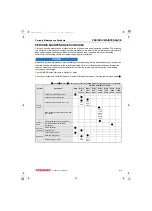
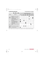
Page 65: ...may affect the warranty coverage on your engine See YANMAR Limited Warranty in Warranty Section Consult your authorized YANMAR dealer or distributor for assistance when checking items marked with a Check Replace Contact your authorized YANMAR industrial engine dealer or distributor System Check item Daily Periodic maintenance interval Every 50 hours Every 250 hours Every 500 hours Every 1000 hours...

Page 66: ...ank Drain fuel filter water separator Check fuel filter water separator Clean fuel filter water separator Replace fuel filter Hoses Replace fuel system and cooling system hoses or every2 yrs Intake and exhaust Clean or replace air cleaner element Complete engine Overall visual check daily Check Replace Contact your authorized YANMAR industrial engine dealer or distributor System Check item Daily P...

Page 67: ...ffect warranty coverage cause internal engine components to seize and or shorten engine life Prevent dirt and debris from contaminating the engine oil Carefully clean the oil cap dipstick and the surrounding area before you remove the cap Never mix different types of engine oil This may adversely affect the lubricating properties of the engine oil Never overfill Overfilling may result in white exh...

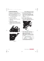
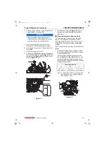
Page 68: ...l pan Allow oil to drain 7 After all oil has been drained from the engine reinstall the oil drain plug Figure 5 2 1 and tighten to 139 8 47 0 ft lb 53 9 63 7 N m 5 5 6 5 kgf m 8 Dispose of used oil properly Remove the engine oil filter as follows 1 Turn the engine oil filter Figure 5 2 2 counterclockwise Figure 5 2 3 using a filter wrench Figure 5 2 2 Clean the engine oil filter mounting face 3 Li...

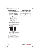
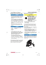
Page 69: ...ay with a clean cloth Check and adjust cooling fan V belt The V belt will slip if it does not have the proper tension This will prevent the alternator from generating sufficient power Also the engine will overheat due to the engine coolant pump pulley slipping Check and adjust the V belt tension deflection as follows 1 Press the V belt down with your thumb with a force of approximately 22 ft lb 98...

Page 70: ...ottom of the pulley groove If there is no clearance Figure 5 6 2 between the V belt and the bottom of the pulley groove replace the V belt Figure 5 6 4 Check the V belt for cracks oil or wear If any of these conditions exist replace the V belt 5 Install the new V belt Refer to the table for proper tension 6 After adjusting run the engine for 5 minutes or more Check the tension again using the spec...

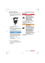
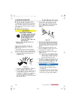
Page 71: ...screw on the top of the fuel filter water separator 2 3 turns counterclockwise Be sure to tighten the air vent screw after the water has drained out NOTICE Always be environmentally responsible Follow the guidelines of the EPA or other governmental agencies for the proper disposal of hazardous materials such as engine oil diesel fuel and engine coolant Consult the local authorities or reclamation ...

Page 72: ... has drained out 5 Open the fuel cock Figure 5 7 3 6 Be sure to prime the diesel fuel system when you are finished See Priming the Fuel System on page 4 16 7 Check for leaks Check battery DANGER Explosion Hazard Never check the remaining battery charge by shorting out the terminals This will result in a spark and may cause an explosion or fire Use a hydrometer to check the remaining battery charge...

Page 73: ... 2 so it is at the upper limit Figure 5 8 1 If operation continues with insufficient battery fluid the battery life is shortened and the battery may overheat and explode During the summer check the fluid level more often than specified Figure 5 8 If the engine cranking speed is so slow that the engine does not start recharge the battery If the engine still will not start after charging have your a...

Page 74: ... or serious injury NOTICE Always be environmentally responsible Follow the guidelines of the EPA or other governmental agencies for the proper disposal of hazardous materials such as engine oil diesel fuel and engine coolant Consult the local authorities or reclamation facility Never dispose of hazardous materials irresponsibly by dumping them into a sewer on the ground or into ground water or wat...

Page 75: ...nment Change the engine oil every 250 hours of operation after the initial change at 50 hours Replace the engine oil filter at the same time See Replace engine oil and engine oil filter on page 5 7 Check and clean radiator fins CAUTION Flying Object Hazard Always wear eye protection when servicing the engine and when using compressed air or high pressure water Dust flying debris compressed air pre...

Page 76: ...articulates Use the lowest possible air pressure to remove the dust without damaging the element 4 If the air cleaner is equipped with a double element only remove and replace the inner element Figure 5 12 1 if the engine lacks power or the dust indicator actuates if equipped Figure 5 12 5 The inner element should not be removed when cleaning or replacing the outer element The inner element is use...

Page 77: ...ce fuel filter DANGER Fire and Explosion Hazard Diesel fuel is flammable and explosive under certain conditions When you remove any fuel system component to perform maintenance such as changing the fuel filter place an approved container under the opening to catch the fuel Never use a shop rag to catch the fuel Vapors from the rag are flammable and explosive Wipe up any spills immediately Wear eye...

Page 78: ...re 5 13 2 and hand tighten it only until it comes in contact with the mounting surface Tighten to 14 17 ft lb 19 6 23 5 N m 2 0 2 4 kgf m or one additional turn using the filter wrench Consult the operation manual for the driven machine for applicability of the dust proof filter 6 Open the fuel cock of the fuel filter water separator 7 Prime the fuel system See Priming the Fuel System on page 4 16...

Page 79: ...r on page 5 11 4 Turn the cup Figure 5 14 1 to the left Figure 5 14 10 and remove the cup Figure 5 14 1 If equipped disconnect the sensor wire from the cup before removing the cup 5 Carefully hold the cup to prevent fuel from spilling If you spill any fuel clean up the spill completely 6 Remove the float ring Figure 5 14 8 from the cup Pour the contaminants into the container and dispose of it pro...

Page 80: ...d Wear eye protection and rubber gloves when you handle long life or extended life engine coolant If contact with the eyes or skin should occur flush eyes and wash immediately with clean water Failure to comply may result in minor or moderate injury NOTICE Always be environmentally responsible Follow the guidelines of the EPA or other governmental agencies for the proper disposal of hazardous mate...

Page 81: ...o remove any rust scale and contaminants Then reinstall and tighten the drain plug or close the drain cock in the radiator Reinstall and tighten the cylinder block drain plug 6 Fill radiator and engine with engine coolant See Filling Radiator with Engine Coolant on page 4 20 Adjust intake exhaust valve clearance Proper adjustment is necessary to maintain the correct timing for opening and closing ...

Page 82: ...page 7 27 This procedure is considered normal maintenance and is performed at the owner s expense This procedure is not covered by the YANMAR Limited Warranty Inspect crankcase breather system Proper operation of the crankcase breather system is required to maintain the emission requirements of the engine The EPA ARB requires that the crankcase breather system is inspected every 1500 hours There a...

Page 83: ...ry Check and replace fuel hoses and engine coolant hoses NOTICE Always be environmentally responsible Follow the guidelines of the EPA or other governmental agencies for the proper disposal of hazardous materials such as engine oil diesel fuel and engine coolant Consult the local authorities or reclamation facility Never dispose of hazardous materials irresponsibly by dumping them into a sewer on ...

Page 84: ... recirculation performance due to carbon accumulation inspect clean and test the valve at least every 3000 hours Consult your local YANMAR dealer for this service Inspect and clean EGR lead valve The EGR lead valve is located in the passage of recirculated gas To prevent carbon accumulation in or clogging of the lead valve inspect and clean the lead valve at regular intervals Consult your local YA...

Page 85: ...nd Timing Gear Train Specifications 6 6 Camshaft 6 6 Idler Gear Shaft and Bushing 6 6 Timing Gear Backlash 6 6 Crankshaft and Piston Specifications 6 7 Crankshaft 6 7 Thrust Bearing 6 7 Piston 6 7 Piston Ring 6 8 Connecting Rod 6 8 Tappet 6 9 Cylinder Block Specifications 6 9 Cylinder Block 6 9 Special Torque Chart 6 10 Torque for Bolts and Nuts 6 10 Special Service Tools 6 11 Measuring Instrument...

Page 86: ...aft Components 6 32 Disassembly of Engine 6 33 Disassembly of Camshaft and Timing Components 6 34 Disassembly of Crankshaft and Piston Components 6 37 Inspection of Crankshaft and Camshaft Components 6 40 Honing and Boring 6 46 Reassembly of Crankshaft and Piston Components 6 47 Reassembly of Camshaft and Timing Components 6 53 Final Reassembly of Engine 6 56 EGR system 6 57 EGR System 6 57 Inspec...

Page 87: ...ore You Begin Servicing BEFORE YOU BEGIN SERVICING Before performing any service procedures within this section read the following safety information and review the Safety section on page 3 1 3TNV88F_SVM_A4 book 3 ページ 2012年7月26日 木曜日 午後6時4分 ...

Page 88: ... Inspection item Standard Limit Reference page Guide inside diameter Intake 0 3154 0 3159 in 8 010 8 025 mm 0 3189 in 8 10 mm See Inspection of valve guides on page 6 23 Valve stem outside diameter 0 3132 0 3140 in 7 955 7 975 mm 0 3110 in 7 90 mm Valve stem bend 0 0014 0 0028 in 0 035 0 070 mm 0 0071 in 0 18 mm Guide inside diameter Exhaust 0 3156 0 3161 in 8 015 8 030 mm 0 3189 in 8 10 mm Valve ...

Page 89: ...age Arm shaft hole diameter 0 6299 0 6307 in 16 000 16 020 mm 0 6327 in 16 07 mm See Inspection of rocker arm assembly on page 6 22 Shaft outside diameter 0 6286 0 6293 in 15 966 15 984 mm 0 6276 in 15 94 mm Oil clearance 0 0006 0 0021 in 0 016 0 054 mm 0 0051 in 0 13 mm Inspection item Standard Limit Reference page Free length 1 6535 in 42 0 mm 1 6339 in 41 5 mm See Inspection of valve springs on...

Page 90: ... diate Bore inside diameter 1 7716 1 7726 in 45 000 45 025 mm 1 7756 in 45 100 mm Camshaft outside diameter 1 7681 1 7691 in 44 910 44 935 mm 1 7667 in 44 875 mm Oil clearance 0 0026 0 0045 in 0 065 0 115 mm 0 0089 in 0 225 mm Flywheel end Bore inside diameter 1 7716 1 7726 in 45 000 45 025 mm 1 7756 in 45 100 mm Camshaft outside diameter 1 7687 1 7697 in 44 925 44 950 mm 1 7673 in 44 890 mm Oil c...

Page 91: ...ge 6 44 Bearing inside diameter 1 9685 1 9693 in 50 000 50 020 mm Bearing insert thickness 0 0785 0 0791 in 1 995 2 010 mm Oil clearance 0 0015 0 0027 in 0 038 0 068 mm 0 0059 in 0 150 mm Inspection item Standard Limit Reference page Crankshaft end play 0 0051 0 0091 in 0 13 0 23 mm 0 0110 in 0 28 mm See Removal of crankshaft on page 6 39 Inspection item Standard Limit Reference page Piston outsid...

Page 92: ...de clearance 0 0014 0 0028 in 0 035 0 070 mm 0 0075 in 0 190 mm End gap 0 0079 0 0157 in 0 200 0 400 mm 0 0193 in 0 490 mm Oil ring Ring groove width 0 1581 0 1587 in 4 015 4 030 mm 0 1626 in 4 130 mm Ring width 0 1563 0 1571 in 3 970 3 990 mm 0 1555 in 3 950 mm Side clearance 0 0010 0 0024 in 0 025 0 060 mm 0 0071 in 0 180 mm End gap 0 0079 0 0157 in 0 200 0 400 mm 0 0193 in 0 490 mm Inspection i...

Page 93: ... of tappets on page 6 44 Tappet stem outside diameter 0 4715 0 4720 in 11 975 11 990 mm 0 4707 in 11 955 mm Oil clearance 0 0004 0 0020 in 0 010 0 050 mm 0 0035 in 0 090 mm Inspection item Standard Limit Reference page Cylinder inside diameter 3 4646 3 4657 in 88 000 88 030 mm 3 4724 in 88 200 mm See Inspection of cylinder block on page 6 41 Cylinder bore Roundness 0 0004 in 0 01 mm or less 0 0012...

Page 94: ...88 2 N m 8 5 9 0 kgf m Applied Main bearing cap bolt M12 1 5 mm 69 72 ft lb 93 2 98 1 N m 9 5 10 5 kgf m Applied Crankshaft pulley bolt M14 1 5 mm Cast metal FC300 62 69 ft lb 83 3 93 1 N m 8 5 9 5 kgf m Applied Steel metal S45C 83 91 ft lb 112 7 122 7 N m 11 5 12 5 kgf m Fuel injector bolt M8 1 25 mm 18 21 ft lb 24 4 28 4 N m 2 5 2 9 kgf m Not applied Fuel pump drive gear nut M14 1 5 mm 58 65 ft ...

Page 95: ...70 92305 4 Connecting rod bushing replacer for removal installation of connecting rod bushing Model L1 L2 d1 d2 3TNV88F 0 787 in 20 mm 3 937 in 100 mm 1 024 in 26 mm 1 142 in 29 mm Locally manufactured 5 Valve spring compressor for removal installation of valve spring YANMAR Part No 129100 92630 6 Stem seal installer for installing valve stem seal Model d1 d2 d3 L1 L2 L3 3TNV88F 0 638 in 16 2 mm 0...

Page 96: ...er bore 3TNV88F 129400 92430 3 268 3 740 in 83 95 mm 10 Piston ring compressor for installing piston YANMAR Part No 95550 002476 The piston insertion tool is applicable for 2 362 4 921 in 60 125 mm diameter pistons 11 Piston ring expander for removal installation of piston ring Available locally 12 Pulley installing tool No Tool name Applicable model and tool size Illustration 002829 01X L2 L1 d1 ...

Page 97: ...er Locally available For measuring the outside diameters of crankshaft pistons piston pins etc 5 Cylinder bore gauge Locally available For measuring the inside diameters of cylinder liners bearing bores etc 6 Calipers Locally available For measuring outside diameters depth thickness and width 7 Depth micrometer Locally available For measuring of valve recession 8 Square Locally available For measu...

Page 98: ...wrench Locally available For tightening nuts and bolts to the specified torque 11 Feeler gauge Locally available For measuring piston ring gaps piston ring clearance and valve adjustment clearance No Instrument name Application Illustration 001437 00X 001438 00X 001426 00X 3TNV88F_SVM_A4 book 14 ページ 2012年7月26日 木曜日 午後6時4分 ...

Page 99: ...ual 6 15 Cylinder Head CYLINDER HEAD Cylinder Head Components Figure 6 1 7 8 9 26 10 11 12 13 14 15 17 18 19 20 21 22 23 24 25 27 28 29 31 30 32 16 33 3 1 2 4 5 6 34 046614 00X00 3TNV88F_SVM_A4 book 15 ページ 2012年7月26日 木曜日 午後6時4分 ...

Page 100: ...g stud 15 Support bolt 16 Rocker arm shaft support 17 Valve cap 18 Valve keepers 19 Spring retainer 20 Valve spring 21 Valve stem seal 22 Valve guide 23 Cylinder head 24 Intake valve 25 Exhaust valve 26 Cylinder head gasket 27 Fuel injector retainer 28 Washer 29 Fuel injector retainer bolt 30 Fuel injector nozzle protector 31 Fuel injector nozzle seat 32 Push rod 33 Crankcase breather components 3...

Page 101: ...hod It is important that all parts are returned to the same position during the reassembly process Figure 6 3 2 Remove the intake manifold bolts Figure 6 4 1 Remove the intake manifold Figure 6 4 2 Discard the intake manifold gasket Figure 6 4 3 Figure 6 4 3 Remove the exhaust manifold bolts Figure 6 4 4 and nuts Figure 6 4 5 Remove the exhaust manifold Figure 6 4 6 and the exhaust manifold gasket...

Page 102: ... removed in advance Failure to remove the glow plugs in advance could result in damages to the glow plugs because their tips are protruding from the cylinder head combustion chamber surface Removal of valve cover 1 Remove the valve cover nuts Figure 6 6 1 2 Remove the O ring Figure 6 6 2 on each valve cover nut Figure 6 6 3 Remove the valve cover Figure 6 6 3 and the valve cover gasket Figure 6 6 ...

Page 103: ...in a padded vise Twist and pull out on the rocker arm shaft to remove Reverse this process when you reinstall the rocker arm shaft into the supports 2 Slide the rocker arm shaft Figure 6 8 3 out of the rocker arm supports Figure 6 8 5 springs Figure 6 8 1 and rocker arms Figure 6 8 2 Note Mark the rocker arms so they can be reinstalled with the original matching valve and pushrod Figure 6 8 3 Remo...

Page 104: ...ad on the work bench with the combustion side down 2 Remove the valve cap Figure 6 12 1 and keep with the valve it was installed on 3 Using the valve spring compressor tool compress one of the valve springs Figure 6 11 Figure 6 11 4 Remove the valve keepers Figure 6 12 2 5 Slowly release the tension on the valve spring 6 Remove the spring retainer Figure 6 12 3 and valve spring Figure 6 12 4 Figur...

Page 105: ...precautions found on containers of hazardoussubstances like parts cleaners primers sealants and sealant removers Failure to comply could result in death or serious injury Thoroughly clean all components using a non metallic brush and an appropriate solvent Each part must be free of carbon metal filings and other debris Inspection of Cylinder Head Components Visually inspect the parts Replace any p...

Page 106: ...arm assembly Rocker arm shaft hole diameter 1 Use a test indicator and micrometer to determine if the inside diameter of all the rocker arm support brackets and the rocker arms Figure 6 15 are within the specified limits See Rocker Arm and Shaft on page 6 5 for the service limit 2 Inspect the contact areas Figure 6 15 1 for excessive wear or damage Figure 6 15 Rocker arm shaft outside diameter Use...

Page 107: ...gure 6 18 If distortion exceeds the service limit resurface or replace the cylinder head Remove only enough material to make the cylinder head flat but do not remove more than 0 008 in 0 20 mm Inspection of intake and exhaust valves Visually inspect the intake and exhaust valves Replace any valves that are obviously discolored heavily pitted or otherwise damaged Valve stem diameter Use a micromete...

Page 108: ...ide to bring the clearance within the limit Roughness or burrs will cause poor seating of a valve Visually inspect the seating surfaces of each valve and valve seat to determine if lapping or grinding is needed Visually inspect all valve faces and valve seats for pitting distortion cracking or evidence of overheating Usually the valves and the valve seats can be lapped or ground to return them to ...

Page 109: ...sing a mixture of valve lapping compound and engine oil Be sure to thoroughly wash all parts to remove all grinding powder or compound Inspection of valve springs Inspect the valve springs If damage or corrosion is seen or if measurements exceed the specified limits replace the springs Fractures Check for fractures on the inside and outside portions of the springs If the valve spring is fractured ...

Page 110: ...he valve guide installation tool Figure 6 28 2 See Valve Guide Projection specification starting on page 6 4 Figure 6 28 Reassembly of intake and exhaust valves NOTICE Always install new valve stem seals The exhaust valve stem seals are different than the intake valve stem seals and can be identified by either the paint marks on the outside of the seals or by the color of the seal spring Figure 6 ...

Page 111: ...valves Reassembly of cylinder head 1 Carefully clean both the combustion surface of the cylinder head and the top surface of the cylinder block Then place a new cylinder head gasket Figure 6 32 2 on the cylinder block 2 Position the cylinder head on the cylinder head gasket Figure 6 32 3 Lightly oil the threads of the cylinder head bolts Figure 6 32 1 Tighten the bolts to the specified torque in t...

Page 112: ...upport Figure 6 35 5 having a hole for the shaft alignment stud Figure 6 35 4 Align the hole in the rocker arm shaft and the hole in the rocker arm support Reinstall the alignment stud Figure 6 35 Note Figure 6 35 shows components for one cylinder Components for all remaining cylinders are assembled in the same order 2 Place the rocker arm shaft assembly onto the cylinder head 3 If removed reinsta...

Page 113: ...he bolts to the specified torque 6 Install each glow plug Figure 6 37 1 and tighten it with the specified torque Install each electrical harness Figure 6 37 1 and tighten it with the specified torque Figure 6 37 7 Reinstall the fuel injectors See Installation of the Fuel Injectors on page 7 31 8 Reinstall the high pressure and the return fuel injection lines See Installation of the Fuel Injectors ...

Page 114: ...head or valves may be possible If adjusting each cylinder individually the cylinder to be adjusted first does not have to be the No 1 cylinder Select and adjust the cylinder where the piston is nearest to the top dead center after turning Make adjustment for the remaining cylinders in the order of firing by turning the crankshaft each time To decrease the number of rotations required to check all ...

Page 115: ...djusting screw lock nut Figure 6 39 1 and valve adjusting screw Figure 6 39 2 on the rocker arm and check the valve for inclination of the valve cap entrance of dirt or wear Figure 6 39 6 Insert a feeler gauge of the correct thickness Figure 6 40 1 see Adjustment Specifications on page 6 4 between the rocker arm and valve cap Turn the valve adjustment screw to adjust the valve clearance so there i...

Page 116: ...aft and Camshaft Components CRANKSHAFT AND CAMSHAFT COMPONENTS Figure 6 41 1 2 5 3 4 6 7 8 9 10 13 14 15 16 17 18 29 30 35 37 36 38 39 40 32 33 34 19 20 21 22 26 27 28 23 24 25 11 12 046622 00X00 3TNV88F_SVM_A4 book 32 ページ 2012年7月26日 木曜日 午後6時4分 ...

Page 117: ...mportant that all parts are returned to the same position during the reassembly process If the engine will be completely disassembled the following preliminary steps should be performed 1 Disconnect the battery cables at the battery Always disconnect the negative cable first 2 Remove the throttle cable electrical connections intake and exhaust system connections and fuel supply lines from the engi...

Page 118: ...using a gear puller 3 Remove the bolts that retain the gear case cover to the cylinder block and oil pan 4 Remove the gear case cover Figure 6 42 1 Figure 6 42 Checking timing gear backlash Prior to removing the timing gears measure the gear backlash and determine the gear wear Check the backlash between each pair of mating gears Figure 6 43 If not within specification replace both mating gears Se...

Page 119: ... the idler gear shaft Figure 6 45 1 Remove the idler gear shaft idler gear Figure 6 45 2 and bushing Figure 6 45 3 Figure 6 45 2 Do not remove the crankshaft gear unless it is damaged and requires replacement If the gear must be removed remove it using a gear puller 3 Removal of the camshaft gear requires the camshaft be removed and placed in a press Do not remove the camshaft gear unless it or th...

Page 120: ...e camshaft at least two turns to bump any sticking tappets away from the camshaft 4 Slowly pull the camshaft Figure 6 50 2 assembly out of the engine being careful not to damage the front camshaft bushing Note If the engine is not installed on an engine repair fixture standtheengineuprightontheflywheel end mounting flange Rotate the camshaft at least two turns to bump the tappets out of the way to...

Page 121: ...e two O rings 6 Remove the O ring Figure 6 51 2 and dowels Figure 6 51 5 Figure 6 51 Disassembly of Crankshaft and Piston Components Removal of pistons NOTICE Keep the piston pin parts piston assemblies and connecting rod assemblies together to be returned to the same position during the reassembly process Label the parts using an appropriate method NOTICE Engines with high operating hours may hav...

Page 122: ... 5 Remove bearing cap 6 Compare the width of the flattened PLASTIGAGE to the graduation marks on the package Figure 6 54 1 The mark that most closely matches the width of the flattened PLASTIGAGE will indicate the bearing oil clearance Figure 6 54 7 Repeat with remaining connecting rods NOTICE Do not allow the connecting rod to contact the crankshaft journal during piston removal Damage to the bea...

Page 123: ... dial gauge Figure 6 57 1 on the cylinder block Move the crankshaft Figure 6 57 2 in and out to measure the end play Record the measurement Figure 6 57 Method B Use a feeler gauge to measure the clearance Figure 6 58 3 between the thrust bearing Figure 6 58 1 and crankshaft Figure 6 58 2 Record the measurement See Thrust Bearing on page 6 7 for the service limit Figure 6 58 4 Remove the main beari...

Page 124: ...ance Figure 6 61 6 Remove the crankshaft from the engine 7 Remove the bearing inserts Figure 6 59 1 and thrust bearings Figure 6 59 2 Note Do not remove the crankshaft gear unless the gear or crankshaft are damaged and require replacement 8 If necessary remove the crankshaft gear Figure 6 62 1 parallel pin Figure 6 62 2 and key Figure 6 62 3 If using a gear puller be careful not to damage the thre...

Page 125: ...pection of cylinder block 1 Ensure that oil passages are clear and unobstructed 2 Check for discoloration or evidence of cracks If a fracture is suspected use the color check method or the Magnaflux method to determine if the cylinder block is fractured 3 Inspect cylinders for roundness taper or evidence of scoring Collect and record the measurements Consider honing reboring or replacing the cylin...

Page 126: ...Measure the diameter of the wrist pin bore on both sides of the piston Figure 6 67 See Piston on page 6 7 for specifications Record the measurements Figure 6 67 7 Measure the outside diameter of the wrist pin in three places and at 90 Figure 6 68 See Piston on page 6 7 for specifications Record the measurements Figure 6 68 8 Using a micrometer measure the thickness of each piston ring See Piston o...

Page 127: ...ge 6 8 for specifications Use a piston ring end gap filing tool to adjust the piston ring end gap on new piston rings 11 Repeat the above steps for each cylinder and piston assembly Inspection of connecting rod 1 Measure the wrist pin bushing bore using a bore gauge Figure 6 71 1 Replace the bushing if not within specifications If the bushing has been removed measure the inside diameter of the con...

Page 128: ...ournals Figure 6 74 4 on V blocks 2 Place a dial indicator Figure 6 74 3 on a center main bearing surface Figure 6 74 3 Rotate the crankshaft and observe runout See Crankshaft on page 6 7 for specifications 4 Use the color check method or Magnaflux to inspect the crankshaft for cracks Replace the crankshaft if evidence of fractures are found 5 Measure the outside diameter of each crankpin Figure 6...

Page 129: ...t and observe the runout See Camshaft on page 6 6 for specifications 3 Measure the height of each lobe Figure 6 77 1 See Camshaft on page 6 6 for specifications Figure 6 77 4 Measure the diameter of the gear end Figure 6 78 1 intermediate Figure 6 78 2 and flywheel end Figure 6 78 3 bearing journals See Camshaft on page 6 6 for specifications Figure 6 78 K0001733A 1 R R 2 K0001711 1 K0001712A K000...

Page 130: ...ctions can be corrected by honing alone 1 Boring Significant cylinder damage may be corrected by boring the cylinder to an oversize dimension Refer to the appropriate parts catalog for available oversize pistons and piston rings Boring a cylinder should always be done in a properly equipped machine shop A bored cylinder should always be finished with a hone to properly prepare the cylinder surface...

Page 131: ...y with compressed air Apply clean engine oil to all steel surfaces to prevent rusting Reassembly of Crankshaft and Piston Components Note Proceed slowly Make no forced assemblies unless a pressing operation is called for All parts must be perfectly clean and lightly lubricated when assembled Use new gaskets seals and O rings during assembly Liberally apply clean engine oil to all internal parts du...

Page 132: ...el Note The actual appearance of the match marks on the piston and connecting rod may vary but they will always be in the same locations 1 Piston identification mark 2 Embossed mark on connecting rod 3 Rod and cap match marks Figure 6 83 Piston to connecting rod orientation by model Orient the piston identification mark stamped on top of the piston on the same side as the rod and cap match marks s...

Page 133: ... reinstall the wrist pin Figure 6 85 3 through the piston and connecting rod 5 Reinstall the second circlip Figure 6 85 4 and ensure it is securely seated in the groove Figure 6 85 Note If installing new piston rings the end gap must be checked and adjusted as necessary See Inspection of pistons piston rings and wrist pin on page 6 41 for specifications Use a piston ring end gap filing tool to adj...

Page 134: ...ls Figure 6 88 1 2 3 Do not position the top piston ring end gap in line with the wrist pin 1 Top compression ring end gap 2 Second compression ring end gap 3 Oil ring end gap Figure 6 88 Installation of crankshaft 1 If removed reinstall the keys and timing gear on the crankshaft 2 Reinstall new bearing inserts Figure 6 89 1 and thrust bearing Figure 6 89 2 in the cylinder block and main bearing c...

Page 135: ... the connecting rod to contact the crankshaft journal during piston installation Damage to the crankshaft bearing journal may result 1 Lubricate the piston piston rings and cylinder with clean engine oil or assembly lubricant 2 Rotate the crankshaft so the crankpin for the piston being installed is near bottom dead center NOTICE Ensure the piston ring gaps are located correctly Figure 6 91 1 Top c...

Page 136: ...ure 6 92 5 of the engine 1 Fuel injection pump side of engine 2 Piston identification mark 3 Embossed mark on connecting rod 4 Rod and cap match marks 5 Flywheel end of engine 6 Camshaft side of engine Figure 6 92 4 Reinstall the bearing inserts Figure 6 93 1 in the connecting rod and cap 5 Apply a liberal coat of clean engine oil to the bearing inserts and crankshaft journal 6 Apply a light coat ...

Page 137: ...nd timing gear Figure 6 96 4 onto the camshaft using a press Note Heat the gear to 356 392 F 180 200 C and press onto the end of the camshaft 2 Rotate the cylinder block so that gravity will keep the tappets Figure 6 96 5 in place and out of the way of the camshaft lobes when the camshaft is being reinstalled Note If the engine is not installed on an engine repair fixture standtheengine upright on...

Page 138: ... bushing is facing toward the top of the engine 6 Ensure all three timing marks Figure 6 97 A B C are aligned 7 When all gears are properly aligned tighten the idler gear retaining bolts to specified torque See Special Torque Chart on page 6 10 for specifications Installation of gear case cover 1 Apply a continuous bead of ThreeBond Liquid Gasket No 1207F YANMAR Part No 977770 1207F to the mountin...

Page 139: ... pan 1 Reinstall the oil pickup tube Figure 6 101 1 using a new O ring Figure 6 101 2 Figure 6 101 2 Apply a continuous bead of ThreeBond Liquid Gasket No 1207F YANMAR Part No 977770 1207F to the mounting surface of the oil pan Figure 6 102 1 Be sure to circle each bolt hole 3 Reinstall the oil pan and tighten the bolts securely Figure 6 102 1 2 3 K0002133 K0001696A 1 2 K0001695A 1 3TNV88F_SVM_A4 ...

Page 140: ...eassembly of cylinder head on page 6 27 3 Reinstall the engine in the machine 4 Reconnect the fuel and coolant lines 5 Reinstall the alternator 6 Reconnect and adjust the throttle cable 7 Reconnect all electrical connections 8 Fill the engine with oil and coolant 9 Reconnect the battery cables negative cable last 3TNV88F_SVM_A4 book 56 ページ 2012年7月26日 木曜日 午後6時4分 ...

Page 141: ...m EGR SYSTEM EGR System 1 EGR pipe 2 Exhaust manifold 3 Cooling water hose EGR valve inlet 4 Cooling water hose EGR valve outlet 5 Intake manifold 6 EGR valve Figure 6 103 1 2 3 4 5 6 046361 00X00 3TNV88F_SVM_A4 book 57 ページ 2012年7月26日 木曜日 午後6時4分 ...
Page 142: ...ne down These surfaces are extremely hot while the engine is operating and could seriously burn you Failure to comply could result in death or serious injury WARNING Entanglement Hazard Stop the engine before you begin to service it Never leave the key in the key switch when you are servicing the engine Someone may accidentally start the engine and not realize you are servicing it This could resul...

Page 143: ... The EGR system uses steel gaskets at the joints between its components parts These steel gaskets are specific to the respective joints When you remove the system s components parts and reinstall them replace the steel gaskets between them with new correct ones 1 Drain the engine cooling water 2 Remove the battery cable from the battery s minus terminal 3 If there is any additional equipment such ...

Page 144: ...e before measuring the resistances EGR valve operation checks 1 After removing each EGR valve from the engine connect the valve with the connector 2 Connect the valve to the battery s minus terminal 3 Turn on the key switch Note that turning on the key switch causes the E ECU to check whether the valve functions properly by opening and shutting it 4 From the exhaust gas inlet visually check whethe...

Page 145: ...n as well as a soft brush to clean the valves taking care not to damage their parts When cleaning the valves take extreme care to prevent water solvent cleaner and other liquid from entering into the motor and coupler terminals otherwise failure may result Lead valves Similarly to the EGR valves the lead valves must be periodically cleaned every 3000 hours because as exhaust gas circulates through...

Page 146: ... fouled clean it by dipping it in carbon cleaner kerosene or some other liquid capable of removing carbon NOTICE Always be environmentally responsible Follow the guidelines of the EPA or other governmental agencies for the proper disposal of hazardous materials such as engine oil diesel fuel and engine coolant Consult the local authorities or reclamation facility Never dispose of hazardous materia...

Page 147: ... 11 Removal of Fuel Injection Pump 7 11 Installation of Fuel Injection Pump 7 15 Checking and Adjusting Fuel Injection Timing 7 20 Determining the Fuel Injection Timing Specification 7 20 Checking Fuel Injection Timing 7 21 Adjusting Fuel Injection Timing 7 24 Fuel Injectors 7 25 Removal of Fuel Injectors 7 25 Testing of Fuel Injectors 7 27 Disassembly and Inspection of Fuel Injectors 7 28 Adjusti...

Page 148: ...FUEL SYSTEM 7 2 3TNV88F Service Manual This Page Intentionally Left Blank 3TNV88F_SVM_A4 book 2 ページ 2012年7月26日 木曜日 午後6時4分 ...
Page 149: ...efore You Begin Servicing BEFORE YOU BEGIN SERVICING Before performing any service procedures within this section read the following safety information and review the Safety section on page 3 1 3TNV88F_SVM_A4 book 3 ページ 2012年7月26日 木曜日 午後6時4分 ...
Page 150: ...e becomes 10 C or higher the CSD is turned off and the engine returns to the normal speed Trochoid Fuel Pump Note The trochoid fuel pump located on the side of the MP fuel injection pump is not a fuel supply pump The function of this pump is to raise the pressure of the fuel supplied by the electric fuel supply pump to the internal fuel pressure required by the MP fuel injection pump The use of an...

Page 151: ...58 65 ft lb 78 88 N m 8 9 kgf m Not applied High pressure fuel injection line nuts 22 25 ft lb 29 34 N m 3 0 3 5 kgf m Not applied Fuel return line bolts 69 87 in lb 7 8 9 8 N m 0 8 1 0 kgf m Not applied Fuel injection pump mounting nuts 17 21 ft lb 23 28 N m 2 3 2 9 kgf m Not applied Fuel injector nozzle case nut 30 33 ft lb 39 2 44 1 N m 4 4 5 kgf m Not applied Fuel injection pump plunger plug 2...

Page 152: ...ave a three character identification mark Figure 7 2 1 The first character starts with V W R or S Figure 7 2 Note Fuel injector identification is critical as each engine has a unique fuel injection pressure The fuel nozzle is specifically matched to the fuel injector by engine model and or engine speed Injector ID mark Fuel injector pressure Fuel injection timing W 2843 2988 PSI 19 6 20 6 MPa 200 ...

Page 153: ...e special service tools may also be available as an MP Fuel Injection Pump Special Tool Set under a different part number in territories serviced by YANMAR America and YANMAR Europe Contact your authorized YANMAR dealer or distributor for details Mituotoyo 2050SB Locally available Check and adjust fuel injection timing Extension rod Mituotoyo 303613 locally available 3 Fuel injection pump plunger ...

Page 154: ...8 Pressure control valve 9 Trochoid pump 10 Oil seal 11 Fuel injection pump cam 12 Engine crankcase 13 Tappet 14 High pressure gallery 15 Overflow orifice 16 Accumulator 17 Timer piston 18 Mono plunger 19 Distributor shaft 20 Fuel return line 21 High pressure fuel injection lines 22 Fuel injector Figure 7 3 K0000034B 3 4 2 1 22 12 5 21 11 18 17 16 15 14 13 17 10 9 8 7 6 19 20 3TNV88F_SVM_A4 book 8...

Page 155: ...FUEL SYSTEM 3TNV88F Service Manual 7 9 Fuel System Components FUEL SYSTEM COMPONENTS Figure 7 4 8 5 4 10 9 7 6 16 15 14 13 12 17 18 11 1 3 2 046798 00X00 3TNV88F_SVM_A4 book 9 ページ 2012年7月26日 木曜日 午後6時4分 ...
Page 156: ...r hub 9 Cold start device CSD 10 Fuel injection pump insulator 11 Fuel injection pump 12 Rear fuel injection pump support 13 Fuel filter water separator 14 Electric fuel supply pump 15 Fuel filter 16 Fuel filter housing 17 Stop solenoid 18 Trochoid fuel pump Electronically controlled engines are equipped with a solenoid valve As shown in the following figure electronically controlled engines use a...

Page 157: ...ith a back up wrench to prevent loosening of the delivery valves 6 First loosen the fuel line nuts at the fuel injectors and then at the fuel injection pump NOTICE Remove or install the high pressure fuel injection lines as an assembly whenever possible Disassembling the high pressure fuel injection lines from the retainers or bending any of the fuel lines will make it difficult to reinstall the f...

Page 158: ...y depending upon engine model 12 Disconnect the lube oil line Figure 7 9 1 and the clamp Figure 7 9 2 from the pump NOTICE Take care to not damage or bend the oil line In some applications it may be preferable to remove the complete oil line assembly from the engine before proceeding Figure 7 9 13 Remove the fuel injection pump drive gear cover Figure 7 10 1 from the gear case cover Figure 7 10 2 ...

Page 159: ...jection pump drive gear Figure 7 11 1 and a matching mark on the bore of the gear case opening Figure 7 11 2 Figure 7 11 NOTICE Do not loosen or remove the four bolts retaining the fuel injection pump drive gear to the fuel injection pump hub Do not disassemble the fuel injection pump drive gear from the hub Correct fuel injection timing will be very difficult or impossible to achieve 16 Do not lo...

Page 160: ...washer Figure 7 14 2 Figure 7 14 20 Locate the mark stamped into the upper outside mounting boss of the fuel injection pump Highlight this mark and make a corresponding mark on the gear case or front plate Figure 7 15 1 Figure 7 15 Note Some model engines may require the intake manifold and fuel injection pump insulator Figure 7 16 2 be removed to access the inner fuel injection pump Figure 7 16 1...

Page 161: ...jection data before replacing the fuel injection pump will void the engine warranty Improper use or misuse of the E ECU may result in death or serious injury due to an abrupt and unexpected increase in engine speed NOTICE If installing a new or recalibrated fuel injection pump locate and record the timing index number located on the pump housing boss on the engine side of the new or recalibrated f...

Page 162: ...r gear Figure 7 20 3 Install a new O ring on the pump mounting flange Apply grease to the O ring to hold it in place during installation of the injection pump Note Ensure the tapered surface of the fuel injection pump shaft is clean and dry 4 Align the key on the fuel injection pump shaft with the keyway in the fuel injection pump drive gear hub Reinstall the fuel injection pump into the fuel inje...

Page 163: ...fuel injection pump retaining nuts to specification See Special Torque Chart on page 7 5 If installing a new fuel injection pump Reinstall the timing grid sticker provided with the new fuel injection pump onto the back of the gear case front plate Figure 7 23 Align the standard mark Figure 7 23 1 with the reference mark Figure 7 23 2 made on the gear case during disassembly Figure 7 23 1 2 046363 ...

Page 164: ... value If the difference between the timing index numbers is a negative number the replacement injection pump must be retarded Figure 7 25 3 rotated toward the engine by the calculated negative amount Each mark on the timing sticker represents 0 5 timing change The above calculated difference indicates that the replacement fuel injection pump is to be installed at 0 5 advanced from the Standard Ma...

Page 165: ...pply line and coolant lines to the fuel injection pump 10 Reinstall the fuel injection high pressure lines Tighten the nuts to specification See Special Torque Chart on page 7 5 NOTICE When reinstalling a new or repaired fuel injection pump it is important to add engine oil to the fuel injection pump to provide lubrication for initial start up Add 5 7 oz 150 200 cc of clean engine oil to the fuel ...

Page 166: ...FUEL INJECTION TIMING Determining the Fuel Injection Timing Specification 1 Locate and record the fuel injection pump timing index number Figure 7 32 1 stamped into the boss on the engine side of the fuel injection pump housing Figure 7 31 1 Treat this number as though there is a decimal point between the two digits i e 68 6 8 Figure 7 31 Figure 7 32 2 Using the FIR number for the engine being ser...

Page 167: ...uel injection pump during this process Make provisions to contain any such spillage 1 Turn off the fuel valve in the fuel supply hose and the fuel return hose 2 Clamp shut the fuel injection pump fuel return hose leading to fuel filter Figure 7 34 1 Figure 7 34 NOTICE Clean thetop of thefuelinjection pump toprevent any contamination when the fuel injection pump plunger plug is removed 3 Remove the...

Page 168: ...the crankshaft pulley bolt rotate the crankshaft in a clockwise direction while looking through the flywheel inspection port Figure 7 37 1 Rotate the crankshaft until the injection timing marks on the flywheel are visible Figure 7 37 7 Typical flywheel markings are as shown in Figure 7 38 1 Note A typical flywheel will have multiple timing grids depending on the number of cylinders Any grid can be...

Page 169: ...If the distance between the two longer marks is approximately 2 0 cm and the distance from the TDC mark is approximately 4 0 cm the answer is approximately 2 This indicates there is 10 2 5 between the TDC mark and the first longer mark on the timing grid That means the first longer mark on the timing grid indicates 10 BTDC the second longer mark indicates 15 BTDC and the third timing mark indicate...

Page 170: ...ion Timing on page 7 24 13 If the injection timing is correct remove the dial indicator and adapter Replace the pump plunger plug and its copper gasket and tighten to specifications Replace the flywheel inspection port cover Open the fuel supply valve and remove the clamp from the fuel supply hose and the fuel return hose 14 Prime the fuel system Operate the engine and check for leaks Adjusting Fu...

Page 171: ...l injection pump away from the engine 7 To retard the injection timing rotate the top of the fuel injection pump toward the engine 8 When the dial indicator reads 2 5 mm 0 098 in of pump plunger lift and the target timing mark on the flywheel aligns with the reference mark on the flywheel housing or engine back plate the injection timing is correct 9 Tighten the fuel injection pump mounting nuts a...

Page 172: ...s Finish loosening all the fuel line nuts and remove the high pressure fuel lines as an assembly being careful not to bend any of the fuel lines Be sure to protect the fuel system from contamination by covering all open connections 3 Remove the return fuel hoses Figure 7 44 1 from one side of each fuel injector 4 Remove the bolts and washers that secure the fuel injector retainers Figure 7 44 2 to...

Page 173: ...ng the engine and when using compressed air or high pressure water Dust flying debris compressed air pressurized water or steam may injure your eyes Failure to comply may result in minor or moderate injury NOTICE Never use a steel wire brush to clean fuel injectors Damage to the nozzle and other components is likely to result 1 Thoroughly clean the fuel injector nozzle using clean diesel fuel and ...

Page 174: ...is tight Service or replace the injector if fuel continues to leak from either the return line fitting or nozzle 6 Pump the operating lever more rapidly to repeatedly pop the injector and observe the spray pattern The pattern should be a very fine uniform spray Figure 7 47 If a dripping or an uneven pattern is seen Figure 7 48 service or replace the injector Figure 7 47 Figure 7 48 If the fuel inj...

Page 175: ... 6 Inspect the sealing surfaces Figure 7 50 2 between the valve stop spacer and nozzle body for nicks or scratches Check the contact area between the valve stop spacer and the nozzle valve Figure 7 50 1 for scoring or pitting Use a magnifier glass to inspect the area Figure 7 50 7 Perform a nozzle valve slide test 1 Wash nozzle body and valve in clean diesel fuel 2 While holding the nozzle body ve...

Page 176: ...ssure threshold by approximately 275 PSI 1 9 MPa 19 kgf cm2 Adding adjusting shims increases the threshold pressure Removing adjusting shims reduces the pressure threshold 1 Disassemble the fuel injector assembly See Disassembly and Inspection of Fuel Injectors on page 7 28 2 Remove or add adjusting shims as needed 3 Reassemble the fuel injector assembly See Reassembly of Fuel Injectors on page 7 ...

Page 177: ...ctor to the original cylinder 4 Reinstall the fuel injector retainers Figure 7 53 2 and torque the retaining bolts to specification 5 Reinstall the fuel return hoses Figure 7 53 1 one on each side of each injector 6 Reinstall the fuel high pressure fuel line assembly and tighten the nuts using a line or flare nut wrench Figure 7 53 7 Prime the fuel system See Priming the Fuel System on page 4 16 8...

Page 178: ...FUEL SYSTEM 7 32 3TNV88F Service Manual Fuel Injectors This Page Intentionally Left Blank 3TNV88F_SVM_A4 book 32 ページ 2012年7月26日 木曜日 午後6時4分 ...
Page 179: ...ystem Diagram 8 4 Engine Coolant Pump Components 8 5 Engine Coolant System Check 8 6 Engine Coolant Pump 8 6 Removal of Engine Coolant Pump 8 6 Disassembly of Engine Coolant Pump 8 8 Cleaning and Inspection 8 8 Reassembly of Engine Coolant Pump 8 10 Installation of Engine Coolant Pump 8 10 3TNV88F_SVM_A4 book 1 ページ 2012年7月26日 木曜日 午後6時4分 ...
Page 180: ...COOLING SYSTEM 8 2 3TNV88F Service Manual This Page Intentionally Left Blank 3TNV88F_SVM_A4 book 2 ページ 2012年7月26日 木曜日 午後6時4分 ...
Page 181: ... Before You Begin Servicing BEFORE YOU BEGIN SERVICING Before performing any service procedures within this section read the following safety information and review the Safety section on page 3 1 3TNV88F_SVM_A4 book 3 ページ 2012年7月26日 木曜日 午後6時4分 ...
Page 182: ...is engine coolant pump is representative of the coolant pumps used on other TNV model engines For specific part detail see the parts catalog for the engine you are working on COOLING SYSTEM DIAGRAM 1 Cylinder head 2 Thermostat 3 Engine coolant pump 4 Radiator 5 Coolant recovery tank 6 Cylinder block Figure 8 1 2 1 4 5 3 6 046371 00X00 3TNV88F_SVM_A4 book 4 ページ 2012年7月26日 木曜日 午後6時4分 ...
Page 183: ...at 4 Thermostat O ring 5 Special O ring 6 Engine coolant pump 7 Temperature switch 8 Gasket 9 Engine coolant pump gasket 10 V belt 11 Engine coolant pump V pulley 12 Spacer 13 Engine coolant fan 14 Water temperature sensor electronically controlled engine Figure 8 2 1 2 3 4 6 9 10 11 12 13 5 14 7 8 K0000031A 01X 3TNV88F_SVM_A4 book 5 ページ 2012年7月26日 木曜日 午後6時4分 ...
Page 184: ...re disassembling it from the engine Check the engine coolant pump shaft bearing for abnormal noise sticking excessive play and water leakage Replace the coolant pump if any of these conditions are present NOTICE If the engine coolant pump must be replaced replace the engine coolant pump as an assembly only Do not attempt to repair the engine coolant pump or replace individual components NOTICE Mak...

Page 185: ...alternator away from the engine and out of the way 6 Remove the engine coolant fan guard if equipped engine coolant fan Figure 8 6 1 spacer Figure 8 6 2 and engine coolant pump V pulley Figure 8 6 3 Figure 8 6 7 Disconnect the coolant hoses and the temperature switch lead wire from the engine coolant pump 8 Remove the engine coolant pump Figure 8 6 4 Discard the gasket FULL LOW K0000074A 1 2 1 046...

Page 186: ...Connect a continuity light or ohmmeter to the temperature switch Connect one lead to the terminal of the switch Figure 8 8 1 and the other lead to the metal portion of the switch Figure 8 8 2 Figure 8 8 2 Place the temperature switch and an accurate thermometer Figure 8 8 3 in engine coolant 3 Slowly increase temperature of the fluid using an external heat source 4 The temperature switch is operat...

Page 187: ...erating Thermostat 1 Check for proper operation of the thermostat Place the thermostat Figure 8 10 1 and an accurate thermometer Figure 8 10 2 in warm water Figure 8 10 2 Slowly increase the temperature of the water using an external heat source 3 The thermostat is operating properly if it starts to open at the temperature value stamped on the flange of the thermostat and fully opens as the temper...

Page 188: ...gine coolant pump and the joint Be sure to use the special O ring Although the O ring dimensions are the same as a commercially available O ring the material is different 2 Reinstall the engine coolant pump bolts Tighten the bolts 3 Inspect and reinstall the coolant hoses and the temperature switch lead wire 4 Reinstall the engine coolant pump V pulley Figure 8 13 1 spacer Figure 8 13 2 engine coo...

Page 189: ...or and engine with engine coolant See Drain flush and refill cooling system with new coolant on page 5 20 NOTICE Only use the engine coolant specified Other engine coolants may affect warranty coverage cause an internal buildup of rust and scale and or shorten engine life Prevent dirt and debris from contaminating the engine coolant Carefully clean the radiator cap and the surrounding area before ...

Page 190: ...COOLING SYSTEM 8 12 3TNV88F Service Manual Engine Coolant Pump This Page Intentionally Left Blank 3TNV88F_SVM_A4 book 12 ページ 2012年7月26日 木曜日 午後6時4分 ...
Page 191: ...ervicing 9 3 Introduction 9 4 Oil Pump Service Information 9 4 Lubrication System Diagram 9 5 Checking Engine Oil Pressure 9 6 Trochoid Oil Pump 9 6 Oil Pump Components 9 6 Disassembly of Oil Pump 9 7 Cleaning and Inspection 9 7 Reassembly of Oil Pump 9 9 3TNV88F_SVM_A4 book 1 ページ 2012年7月26日 木曜日 午後6時4分 ...
Page 192: ...LUBRICATION SYSTEM 9 2 3TNV88F Service Manual This Page Intentionally Left Blank 3TNV88F_SVM_A4 book 2 ページ 2012年7月26日 木曜日 午後6時4分 ...
Page 193: ... 3 Before You Begin Servicing BEFORE YOU BEGIN SERVICING Before performing any service procedures within this section read the following safety information and review the Safety section on page 3 1 3TNV88F_SVM_A4 book 3 ページ 2012年7月26日 木曜日 午後6時4分 ...
Page 194: ...t low idle speed 1500 1800 min 1 2000 2500 min 1 2600 min 1 2700 min 1 2800 min 1 2900 3000 min 1 0 29 0 44 MPa 3 0 4 5 kgf cm2 0 34 0 49 MPa 3 5 5 0 kgf cm2 0 39 0 54 MPa 4 0 5 5 kgf cm2 0 06 MPa 0 6 kgf cm2 or greater Inspection item Standard Limit Reference page Plate bearing inside diameter 0 3937 0 3943 in 10 000 10 015 mm 0 3953 in 10 040 mm See Check rotor shaft clearance on page 9 8 Rotor ...

Page 195: ...zzles Idle gear shaft Pressure regulator valve Oil pump Oil suction pipe strainer Cylinder body main gallery Camshaft bearing Rocker arm bearing Rocker arm Tappet cam face Oil pressure switch Bypass valve Oil filter Crank pin Crank journal Fuel injection pump Oil pan 046648 00EN00 3TNV88F_SVM_A4 book 5 ページ 2012年7月26日 木曜日 午後6時4分 ...
Page 196: ...gauge indicates good oil pressure replace the faulty oil pressure switch or sending unit or faulty machine oil pressure gauge in instrument panel If the mechanical oil pressure test gauge indicates low oil pressure troubleshoot the lubrication system to locate the cause of the low oil pressure See Failure Diagnostic List on page 14 9 Repair as necessary TROCHOID OIL PUMP Oil Pump Components The oi...

Page 197: ... 1 from the gear case flange Figure 9 5 2 3 You can remove by hand the lubricating oil pump cover Figure 9 3 5 and outer rotor Figure 9 3 4 Figure 9 5 Cleaning and Inspection Clean the lubricating oil pump pressure regulator valve Figure 9 3 7 and rotor inserting portion Check the parts for wear or flaw Replace the parts with new ones as needed NOTICE Never overfill the engine with engine oil Alwa...

Page 198: ...ide clearance Inspect the side clearance between the lubricating oil pump body and the outer rotor To measure the side clearance use a straight edge and feeler gauge as shown in Figure 9 8 or a depth micrometer Figure 9 8 Record the measurement s and see Rotor shaft clearance on page 9 4 for the service limits Check rotor shaft clearance Inspect the rotor shaft clearance Measure the outside diamet...

Page 199: ...assembly to the gear case flange by tightening the bolts with the specified torque 5 Install the gear case cover For more information See Installation of gear case cover on page 6 54 6 Install the crank shaft pulley 7 Install the cooling water pump V pulley Figure 9 10 1 spacer Figure 9 10 2 cooling water fan Figure 9 10 3 and fan guard if equipped Figure 9 10 8 Install the V belt Adjust the belt ...

Page 200: ...LUBRICATION SYSTEM 9 10 3TNV88F Service Manual Trochoid Oil Pump This Page Intentionally Left Blank 3TNV88F_SVM_A4 book 10 ページ 2012年7月26日 木曜日 午後6時4分 ...
Page 201: ...tion 10 4 Standard and Optional 10 4 Starter Motor Specifications 10 5 Starter Motor Troubleshooting 10 6 Starter Motor Components 10 7 Starter Motor 10 8 Removal of Starter Motor 10 8 Disassembly of Starter Motor 10 8 Inspection and Maintenance 10 11 No load Test 10 18 Installation of Starter Motor 10 18 3TNV88F_SVM_A4 book 1 ページ 2012年7月26日 木曜日 午後6時4分 ...
Page 202: ...STARTER MOTOR 10 2 3TNV88F Service Manual This Page Intentionally Left Blank 3TNV88F_SVM_A4 book 2 ページ 2012年7月26日 木曜日 午後6時4分 ...
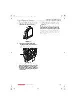
Page 203: ... Before You Begin Servicing BEFORE YOU BEGIN SERVICING Before performing any service procedures within this section read the following safety information and review the Safety section on page 3 1 3TNV88F_SVM_A4 book 3 ページ 2012年7月26日 木曜日 午後6時4分 ...
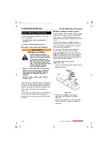
Page 204: ...tage Amperage draw Torque min 1 rpm 129129 77010 Denso 228000 0251 DC 12 V 1 6 hp 1 2 kW 11 5 90 A MAX 3000 8 280 Max 87 in lb 9 81N m 1 0 kgf m 900 129407 77010 Denso 228000 3732 DC 12 V 1 9 hp 1 4 kW 11 5 90 A MAX 3000 8 5 350 Max 117 in lb 13 2N m 1 4 kgf m 1000 129608 77010 Hitachi S114 817A DC 12 V 1 9 hp 1 4 kW 11 90 A MAX 2700 8 4 250 Max 74 in lb 8 3 N m 0 9 kgf m 1000 129242 77010 Hitachi...

Page 205: ...t 100 C 212 F 8 0 V max Pinion DP number of teeth 10 12 11 Difference o ring oil seal Dry none Application Standard Brush Spring force 14 5 18 0 N 1 5 1 8 kgf Height Standard 17 mm 0 67 in Limit 12 mm 0 47 in Magnetic switch Series coil resistance 0 37 Shunt coil resistance 0 62 Commutator Outside diameter Standard ø29 0 mm 1 14 in Limit ø28 0 mm 1 10 in Run out Standard 0 05 mm 0 002 in Limit 0 1...

Page 206: ...W VKLIW OHYHU IRU GHIRUPDWLRQ return spring for fatigue and pinion for sliding 5HSDLU PHVKLQJ EHWZHHQ SLQLRQ DQG ring gear or replace as needed Replace engine oil Repair or replace starter motor Solenoid switch assembly contact defective Repair or replace 5HSDLU RU UHSODFH NH VZLWFK VWDUWLQJ motor relay or magnetic switch assembly If a problem occurs Immediately disconnect battery negative termina...

Page 207: ...ng 9 Shift lever 10 Torsion spring 11 Plunger 12 Dust covers shims 13 Magnetic switch assembly solenoid 14 Cover 15 M6 bolts 2 used 16 Armature assembly 17 Field coil assembly 18 Positive brushes 19 Negative brushes 20 Brush holder assembly 21 Rear cover 22 M5 through bolts 2 used 23 M4 bolts 2 used Figure 10 1 1 3 2 4 5 6 7 8 9 10 11 12 13 14 15 23 18 22 21 20 19 17 16 K0000103A 3TNV88F_SVM_A4 bo...

Page 208: ...following procedures are typical and may differ from the stater being serviced Removal of Starter Motor 1 Disconnect the battery cables at the battery negative cable first 2 Remove the electrical wires from the magnetic switch assembly 3 Remove the starter mounting bolts Figure 10 2 1 Remove the starter motor from the flywheel housing Figure 10 2 Disassembly of Starter Motor 1 M8 nut Remove the M8...

Page 209: ... a screw driver Figure 10 6 8 Brush holder Pull out the brush holder from the outer commutator while caring not to damage the brush Figure 10 7 9 Yoke 10 Armature 11 Center bracket A The permanent magnet is installed in the inner yoke Pull out the armature quietly not to damage the magnet for disassembly Figure 10 8 6 5 4 046415 00X00 Screw driver 7 Motor lead wire 046416 00EN00 Brush Commutator 0...

Page 210: ...ure 10 10 17 Pinion stopper clip Move the pinion stopper to the pinion side and pull out the pinion stopper clip from the groove of the pinion shaft by using a screw driver Care must be taken not to damage the pinion shaft surface while removing the clip Figure 10 11 18 Pinion stopper 19 Pinion clutch If you remove the pinion stopper clip from the pinion shaft the pinion stopper and the pinion clu...

Page 211: ...on and Maintenance 1 Armature 1 Outer diameter of commutator Measure the outer diameter of the commutator If it is below the limit replace it with a non defective Figure 10 15 2 Conduction test for armature coil Check between the commutator bars with a tester If there is conduction it is a non defective Figure 10 16 Pinion shaft Special tools 20 046421 00EN00 21 21 23 22 046422 00X00 Standard Limi...

Page 212: ...ator outer diameter by placing the dial gauge in the shaft center If it is above the limit correct or replace it with a non defective Figure 10 18 5 Inspection of commutator outer diameter surface If the outer diameter surface of the commutator is rough polish it with a No 500 600 sandpaper Figure 10 19 Conduction Coil short circuit Replace the armature Standard Limit Armature 0 05 mm or less 0 1 ...

Page 213: ...conduction between the brush holder positive side and the base negative side with a tester If there is no conduction it is a non defective Figure 10 22 2 Inspection of brush spring Measure the brush spring load after aligning the brush position to the commutator outer diameter If it is out of range replace the brush spring Figure 10 23 Standard Limit 0 5 0 8 mm 0 2 mm Standard Limit 17 mm 12 mm Ha...

Page 214: ... the plunger on the lower side and push down the magnetic switch fully until the end At this time check the conduction between the B terminal and the M terminal If there is conduction it is a non defective Figure 10 26 5 Pinion clutch 1 Hold the clutch outer diameter and turn the pinion by hand Inspect that the pinion turns smoothly when turned in the drive direction and the pinion locks when turn...

Page 215: ...r bearing Measure the inner diameter of the rear cover bearing If it exceeds the wear limit replace it Figure 10 30 3 Center bracket P bearing Measure the inner diameter of the center bracket P bearing If it exceeds the wear limit replace it Figure 10 31 Standard Wear limit 12 5 12 527 mm 12 6 mm Permanent magnet 046441 00EN00 12 5 0 027 0 046440 00X00 Standard Wear limit 12 0 12 018 mm 12 1 mm St...

Page 216: ...or 4 Pinion shaft bearing Measure the inner diameter of the pinion shaft bearing If it exceeds the wear limit replace it Figure 10 32 Standard Wear limit 6 735 6 740 mm 6 83 mm ø6 7 0 040 0 035 046439 00X00 3TNV88F_SVM_A4 book 16 ページ 2012年7月26日 木曜日 午後6時4分 ...

Page 217: ...on to the direction of arrow and measure the gap with the stopper L Note Perform the measurement within 10 seconds Figure 10 33 2 Adjustment method If the gap 1 is except for the L standard value make adjustment by either inserting the dust cover packing or removing it Figure 10 34 1 Switch M8 nut 7 4 8 9 N m 2 M6 bolt 5 4 8 3 N m 3 M4 screw 1 7 2 3 N m 4 M5 through bolt 4 9 6 3 N m Part Shift lev...

Page 218: ...y negative terminal Figure 10 35 5 and the main positive battery terminal Figure 10 35 3 on the starter motor 5 Install a switch Figure 10 35 6 in a circuit between the battery positive terminal Figure 10 35 2 and the starter magnetic switch solenoid terminal Figure 10 35 8 on the starter motor 6 Use a suitable tachometer to monitor the rpm of the starter 7 Turn the switch to the ON position Monit...

Page 219: ...ts 11 7 Alternator Wiring Diagram 11 8 Alternator Standard Output 11 9 Alternator 11 10 Removal of Alternator 11 10 Disassembly of Alternator 11 10 Reassembly of Alternator 11 12 Installation of Alternator 11 14 Dynamo Component Location 11 15 Dynamo Wiring Diagram 11 16 Operation of Dynamo 11 16 Dynamo Standard Output 11 17 Testing of Dynamo 11 18 Testing Stator Coil Continuity 11 18 Testing Stat...

Page 220: ...ALTERNATOR 11 2 3TNV88F Service Manual Disassembly of Dynamo 11 19 Reassembly of Dynamo 11 19 Installation of Dynamo 11 20 3TNV88F_SVM_A4 book 2 ページ 2012年7月26日 木曜日 午後6時4分 ...

Page 221: ...efore You Begin Servicing BEFORE YOU BEGIN SERVICING Before performing any service procedures within this section read the following safety information and review the Safety section on page 3 1 3TNV88F_SVM_A4 book 3 ページ 2012年7月26日 木曜日 午後6時4分 ...

Page 222: ...the engine you are working on DYNAMO AND ALTERNATOR INFORMATION Standard and Optional Dynamos Standard and Optional Alternators YANMAR Part No Mfg Mfg Part No Specification 171301 77201 Kokusan GP8138 DC 12 V 15 A 119910 77200 Kokusan GP9191 DC 12 V 20 A YANMAR Part No Mfg Mfg Part No Specification 119620 77201 Denso 100211 4531 DC 12 V 40 A 129423 77200 Denso 101211 1170 DC 12 V 40 A with pulse 1...

Page 223: ... circuit Integrated regulator IC regulator Outside diameter of pulley 2 724 in 69 2 mm Belt shape Type A YANMAR Part No 119910 77200 Nominal output 20 A Weight 3 97 lb 1 8 kg Revolution direction as viewed from pulley Clockwise Rating Continuous Battery voltage 12 V Rated revolution 3500 min 1 rpm Operating range 1400 6600 min 1 rpm Grounding characteristics Negative side of circuit Regulator Curr...

Page 224: ...lso applicable to the bench test With engine idling measure voltage at L terminal and at battery With engine idling turn light switch ON Replace the battery indicator Battery indicator is available from driven machine manufacturer Battery indicator flashes Battery voltage is between 13 and 15 volts Battery voltage greater than 15 5 volts Battery voltage minus L terminal voltage is greater than 0 5...

Page 225: ...6 Stud 2 used 7 Front frame housing bearing 8 Bearing cover 9 Bearing cover bolt 4 used 10 Rotor assembly 11 Rear frame housing bearing 12 Bearing cover 13 Thrust washer 14 Thrust washer 15 Nut 2 used 16 Nut 17 Insulation bushing 18 Spring 2 used 19 Brush holder 20 Rear frame housing 21 Bolt 2 used 22 Holder 23 IC regulator assembly 24 Bolt 2 used 25 Bolt 26 Brush 2 used 27 Bolt 28 Rear cover 29 B...

Page 226: ...harging system between alternator terminals IG and L Damage to the alternator will result NOTICE Do not connect a load between alternator terminals L and E Damage to the alternator will result NOTICE Do not remove the positive battery cable from alternator terminal B while the engine is operating Damage to the alternator will result L IG B P L IG IC B F E 0 5PF E PI P 1 5 6 2 4 3 3 B A T 3TNV88F_S...

Page 227: ...rnator Standard Output ALTERNATOR STANDARD OUTPUT Figure 11 3 Alternator speed 10 min 1 13 5 V constant ambient temperature at 77 F 25 C Output current Cold Hot 60 50 40 30 20 10 0 1 2 3 4 5 6 7 8 3TNV88F_SVM_A4 book 9 ページ 2012年7月26日 木曜日 午後6時4分 ...

Page 228: ...nator 1 Disconnect the electrical wires from the alternator 2 Loosen the V belt CAUTION Pinch Hazard Carefully rotate the alternator toward the cylinder block while loosening the V belt Failure to comply may result in minor or moderate injury 3 Remove the V belt adjuster from the alternator bolt Figure 11 4 1 4 Remove the nut Figure 11 4 2 from the gear case stud Remove the alternator Figure 11 4 ...

Page 229: ... bolts retaining the holder Figure 11 7 2 to the rear frame housing Remove the holder 6 Remove the nut Figure 11 7 3 retaining the insulation bushing Figure 11 7 4 Remove the insulation bushing 7 Remove the two bolts Figure 11 8 1 and two nuts Figure 11 8 2 securing the rear frame housing to the front frame housing Figure 11 8 8 Using a press remove the rotor assembly Figure 11 9 1 from the front ...

Page 230: ...aring 11 If it is necessary to replace the bearing Figure 11 11 1 in the rear frame housing use a puller to remove Discard the bearing Remove the bearing cover Figure 11 11 2 and two thrust washers Figure 11 11 3 Figure 11 11 Reassembly of Alternator 1 If removed reinstall the two trust washers Figure 11 12 3 and bearing cover Figure 11 12 2 in the rear frame housing Lubricate the outside diameter...

Page 231: ...4 1 Press the rotor assembly into the front frame housing Figure 11 14 2 and rear frame housing Figure 11 14 3 Figure 11 14 5 Align the front frame housing with the rear frame housing Reinstall the two bolts Figure 11 15 1 and two nuts Figure 11 15 2 Figure 11 15 6 Reinstall the insulation bushing Figure 11 16 4 and nut Figure 11 16 3 Figure 11 16 7 Reassemble the regulator assembly Figure 11 16 1...

Page 232: ...t adjuster bolt Figure 11 19 1 Figure 11 19 2 Reconnect the electrical wires to the alternator Tighten the nuts to 15 20 in lb 1 7 2 3 N m 17 23 kgf m 3 Reinstall the V belt Tighten the V belt to the proper tension as described in Check and adjust cooling fan V belt on page 5 9 4 Start the engine Listen for any unusual sounds from the alternator NOTICE Do not operate the engine if the alternator i...

Page 233: ...ynamo For specific part detail see the Parts Catalog for the engine you are working on 1 Rear cover 2 Nut 3 Lock washer 4 Flat washer 5 Rear bearing 6 Output wire and connector 7 Plate 8 Spacer 9 Stator assembly 10 Front bearing 2 used 11 Flat washer 12 Flywheel assembly 13 Pulley half 14 Through bolt Figure 11 20 K0002140X 1 2 3 6 4 5 7 8 9 10 11 12 13 14 3TNV88F_SVM_A4 book 15 ページ 2012年7月26日 木曜日...

Page 234: ... series of permanent magnets that rotate around a stationary stator coil The magnets are attached to the flywheel which is rotated via the engine cooling fan drive belt The resultant output is an AC alternating current signal The AC is converted to DC direct current by the current limiter The current limiter outputs charging DC current to the battery K0002137X 1 2 3 4 5 6 3TNV88F_SVM_A4 book 16 ペー...

Page 235: ...ual 11 17 Dynamo Standard Output DYNAMO STANDARD OUTPUT Figure 11 22 K0002138E 25 20 15 10 5 0 1 2 3 4 5 6 Standard characteristics 12 V Alternator speed min 1 Output current A 7 103 3TNV88F_SVM_A4 book 17 ページ 2012年7月26日 木曜日 午後6時4分 ...

Page 236: ...egulated Output 1 Test and record the battery voltage with the engine not running 2 Start the engine and operate it at normal operating rpm 3 Again check the battery voltage with the engine running Results The meter reading with the engine running must be higher than with the engine not running If results are not correct test the stator for continuity and shorts to the ground Check the charging sy...

Page 237: ...heel Figure 11 25 3 flat washer Figure 11 25 4 bearings Figure 11 25 5 and spacer Figure 11 25 6 Figure 11 25 4 Remove the screws Figure 11 26 1 and the stator assembly Figure 11 26 2 5 Remove the rear bearing Figure 11 26 3 Figure 11 26 Reassembly of Dynamo 1 Reinstall the rear bearing Figure 11 27 3 2 Reinstall the stator Figure 11 27 2 and screws Figure 11 27 K0002143X 1 2 3 4 K0002144X 6 5 4 3...

Page 238: ...stall the nut Figure 11 30 2 on the gear case stud and the V belt adjuster bolt Figure 11 30 1 Figure 11 30 2 Reconnect the dynamo output wire connector 3 Reinstall the V belt Tighten the V belt to the proper tension as described in Check and adjust cooling fan V belt on page 5 9 4 Start the engine Listen for any unusual sounds from the alternator NOTICE Do not operate the engine if the alternator...

Page 239: ...88F Service Manual Section 12 ELECTRONIC CONTROL SYSTEM Page Before You Begin Servicing 12 3 Introduction 12 4 Electronic Control System 12 4 Electronic control harness connections 12 5 3TNV88F_SVM_A4 book 1 ページ 2012年7月26日 木曜日 午後6時4分 ...

Page 240: ...ELECTRONIC CONTROL SYSTEM 12 2 3TNV88F Service Manual This Page Intentionally Left Blank 3TNV88F_SVM_A4 book 2 ページ 2012年7月26日 木曜日 午後6時4分 ...

Page 241: ... You Begin Servicing BEFORE YOU BEGIN SERVICING Before performing any service procedures within this section read the following safety information and review the Safety section on page 3 1 12_3TNV88F_SVM_Electronic_Control_System fm 3 ページ 2012年7月26日 木曜日 午後6時49分 ...

Page 242: ...ssion control regulations Figure 12 1 illustrates the electronic engine control system Features of the electronic engine control system include Engine speed control schemes Droop control Low idling speed up Auto deceleration High idling speed down Black smoke suppression Starting aid Auto preheating After heating Engine failure detection CAN communication with the control system of the driven mach...

Page 243: ...ELECTRONIC CONTROL SYSTEM 3TNV88F Service Manual 12 5 Electronic control harness connections ELECTRONIC CONTROL HARNESS CONNECTIONS 3TNV88F_SVM_A4 book 5 ページ 2012年7月26日 木曜日 午後6時4分 ...

Page 244: ...ELECTRONIC CONTROL SYSTEM 12 6 3TNV88F Service Manual Electronic control harness connections 3TNV88F_SVM_A4 book 6 ページ 2012年7月26日 木曜日 午後6時4分 ...

Page 245: ...tion 13 ELECTRIC WIRING Page Electric Wiring Precautions 13 3 Electrical Wire Resistance 13 4 Battery Cable Resistance 13 5 Electrical Wire Sizes Voltage Drop 13 6 Conversion of AWG to European Standards 13 7 3TNV88F_SVM_A4 book 1 ページ 2012年7月26日 木曜日 午後6時4分 ...

Page 246: ...ELECTRIC WIRING 13 2 3TNV88F Service Manual This Page Intentionally Left Blank 3TNV88F_SVM_A4 book 2 ページ 2012年7月26日 木曜日 午後6時4分 ...

Page 247: ... resistance of the battery cable in both directions between the starter motor and the battery is within the value indicated in the Battery Cable Resistance chart in the Electric Wiring Section of this manual The starter motor will malfunction and fail if the resistance is higher than the specified value NOTICE Removing the battery cables or the battery while the engine is operating may cause damag...

Page 248: ...xample Current draw of 100 Amps 3 feet of 4 AWG wire 100 Amps 3 Feet 0 000270 0 08 Volts Voltage drop AWG Metric nominal mm Ohms foot resistance 20 0 5 0 009967 18 0 8 0 006340 16 1 25 0 004359 14 2 0 002685 12 3 0 001704 10 5 0 001073 8 8 0 000707 6 15 0 000421 4 20 0 000270 2 30 0 000158 1 40 0 000130 0 1 0 50 0 000103 00 2 0 60 0 000087 000 3 0 85 0 000066 0000 4 0 100 0 000051 3TNV88F_SVM_A4 b...

Page 249: ...02 For starter motors of greater than 2 68 HP 2 kW the total resistance must be less than 0 0012 AWG mm Maximum total battery cable length positive cable negative cable a 12 V starter motor output Less than 2 68 HP 2 kW Greater than 2 68 HP 2 kW m ft m ft 6 15 1 5 4 75 N A N A 4 20 2 3 7 4 N A N A 2 30 3 8 12 6 2 3 7 5 1 40 4 6 15 3 2 8 9 2 0 1 0 50 5 9 19 5 3 5 11 6 00 2 0 60 7 0 22 8 4 2 13 7 00...

Page 250: ...0 3 0 4 0 4 0 4 0 60 6 4 4 2 2 1 0 2 0 3 0 3 0 4 0 4 0 4 0 70 6 4 2 2 1 0 2 0 3 0 3 0 4 0 4 0 80 6 4 2 2 1 0 3 0 3 0 4 0 4 0 90 4 2 2 1 0 2 0 3 0 4 0 4 0 100 4 2 2 1 0 2 0 3 0 4 0 24 Volts 5 18 18 18 16 16 14 12 12 12 10 10 10 10 10 8 8 8 8 8 10 18 16 14 12 12 10 10 10 8 8 8 6 6 6 6 6 6 6 6 15 16 14 12 12 10 10 8 8 6 6 6 6 6 4 4 4 4 4 2 20 14 12 10 10 10 8 6 6 6 6 4 4 4 4 2 2 2 2 2 25 12 12 10 10 ...

Page 251: ...723 0 412 20 0 812 0 519 19 0 992 0 653 18 1 024 0 823 17 1 15 1 04 16 1 29 1 31 15 1 45 1 65 14 1 63 2 08 13 1 83 2 63 12 2 05 3 31 11 2 30 4 15 10 2 59 5 27 9 2 91 6 62 8 3 26 8 35 7 3 67 10 6 6 4 11 13 3 5 4 62 16 8 4 5 19 21 2 3 5 83 26 7 2 6 54 33 6 1 7 35 42 4 0 1 0 8 25 53 4 00 2 0 9 27 67 5 000 3 0 10 40 85 0 0000 4 0 11 68 107 2 00000 5 0 13 12 135 1 000000 6 0 14 73 170 3 1 1 circular mi...

Page 252: ...ELECTRIC WIRING 13 8 3TNV88F Service Manual Conversion of AWG to European Standards This Page Intentionally Left Blank 3TNV88F_SVM_A4 book 8 ページ 2012年7月26日 木曜日 午後6時4分 ...

Page 253: ...ection 14 FAILURE DIAGNOSIS Page Special Service Tools 14 3 Troubleshooting By Measuring Compression Pressure 14 4 Compression Pressure Measurement Method 14 4 Quick Reference Table For Troubleshooting 14 7 3TNV88F_SVM_A4 book 1 ページ 2012年7月26日 木曜日 午後6時4分 ...

Page 254: ...FAILURE DIAGNOSIS 14 2 3TNV88F Service Manual This Page Intentionally Left Blank 3TNV88F_SVM_A4 book 2 ページ 2012年7月26日 木曜日 午後6時4分 ...

Page 255: ...CIAL SERVICE TOOLS Compression gauge kit For measuring compression pressure YANMAR Gauge Set Part No TOL 97190080 Adapter for direct injection 2 valve cylinder head YANMAR Adapter Part No 119802 92950 K0000849 0 3 1 K0000850 3TNV88F_SVM_A4 book 3 ページ 2012年7月26日 木曜日 午後6時4分 ...

Page 256: ...ine Remove the high pressure fuel injection lines as an assembly from the engine 3 Remove the fuel injector from the cylinder to be measured See Removal of Fuel Injectors on page 7 25 NOTICE Remove or install the high pressure fuel injection lines as an assembly whenever possible Disassembling the high pressure fuel injection lines from the retainers or bending any of the fuel lines will make it d...

Page 257: ... and compression gauge adapter from the cylinder 9 Reinstall the fuel injector high pressure fuel injection lines and reconnect the stop solenoid See Reassembly of Fuel Injectors on page 7 30 10 Turn on the fuel supply valve and reconnect the injection pump stop solenoid 11 Prime the fuel system Check for leaks Test the engine 1 3TNV88F_SVM_A4 book 5 ページ 2012年7月26日 木曜日 午後6時4分 ...

Page 258: ...4 3 Compression pressure at 250 min 1 rpm Deviation between cylinders Standard Limit 483 513 PSI 3 33 3 53 MPa 34 36 kgf cm 384 414 PSI 2 65 2 85 MPa 27 29 kgf cm 29 43 PSI 0 2 0 3 MPa 2 3 kgf cm 200 250 300 350 400 Engine speed min 1 569 psi 40 Kgf cm2 4 MPa 3 MPa 2 MPa 498 psi 35 Kgf cm2 427 psi 30 Kgf cm2 284 psi 20 Kgf cm2 356 psi 25 Kgf cm2 K0000802E01 3TNV88F_SVM_A4 book 6 ページ 2012年7月26日 木曜日...

Page 259: ...ve action 1 Air cleaner element Clogged element Clean the element Broken element Replace the element Defect at element seal portion 2 Valve clearance Excessive or no clearance Adjust the valve clearance 3 Valve timing Incorrect valve clearance Adjust the valve clearance 4 Cylinder head gasket Gas leak from gasket Replace the gasket Retighten the cylinder head bolts to the specified torque 5 Intake...

Page 260: ...FAILURE DIAGNOSIS 14 8 3TNV88F Service Manual Quick Reference Table For Troubleshooting This Page Intentionally Left Blank 3TNV88F_SVM_A4 book 8 ページ 2012年7月26日 木曜日 午後6時4分 ...

Page 261: ...White exhaust color Black exhaust color Engine system Intake exhaust valve clearance incorrect Valve clearance adjustment See Measuring and Adjusting Valve Clearance on page 6 30 Compression failure at valve seat Valve seat facing See Valve face and valve seat on page 6 24 Intake exhaust valve seizure Correction or replacement of intake exhaust valve See Removal of intake exhaust valves on page 6 ...

Page 262: ...e Engine oil check See Adding Engine Oil on page 4 18 Symptoms and conditions of failures Cause Defective start Engine stall after start Defective rotation control Insufficient engine output Noise vibration Lubricant Cooling water Intake Exhaust Fuel Electrics electronics Action Referenced page number Starter not rotate Starter rotates Exhaust fume Speed change by accelerator not available constan...

Page 263: ...ke Air filter clogged Cleaning of air filter See Clean air cleaner element on page 5 16 Engine operation at high temperature or high land Consideration of matching output reduction with load Exhaust pipe clogged Cleaning of exhaust pipe Symptoms and conditions of failures Cause Defective start Engine stall after start Defective rotation control Insufficient engine output Noise vibration Lubricant ...

Page 264: ...replacement of speed sensor Repair or replacement of fuel injection pump Monitor the engine rotational speed by the diagnosis tool Rack position sensor signal error Level that ECU can t detect Repair or replacement of fuel injection pump Monitor the rack position sensor signal by the diagnosis tool Operation defect of rack actuator Level that ECU can t detect Repair or replacement of fuel injectio...

Page 265: ...rt circuit of start assist relay Repair or replacement of harness Relay replacement For harness inspection method See Failure Diagnosis on page 14 1 Main relay OFF not available Relay replacement Disconnection short circuit of rack actuator relay Repair or replacement of harness Relay replacement For harness inspection method See Failure Diagnosis on page 14 1 Malfunction by ECU self diagnosis ECU...

Page 266: ...FAILURE DIAGNOSTIC LIST 14 14 3TNV88F Service Manual Failure Diagnostic List This Page Intentionally Left Blank 3TNV88F_SVM_A4 book 14 ページ 2012年7月26日 木曜日 午後6時4分 ...

Reviews: