


ALTERNATOR
12-18
TNV DI Service Manual
Dynamo Wiring Diagram
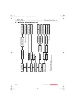
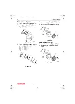
DYNAMO WIRING DIAGRAM
1 – Dynamo
2 – Current Limiter
3 – Key Switch
4 – Charge Lamp (3.4 Watts Max.)
5 – Battery
6 – Load
Figure 12-21
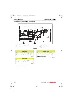
OPERATION OF DYNAMO
The dynamo consists of a series of permanent
magnets that rotate around a stationary stator coil.
The magnets are attached to the flywheel which is
rotated via the engine cooling fan drive belt. The
resultant output is an AC (alternating current)
signal. The AC is converted to DC (direct current)
by the current limiter. The current limiter outputs
charging DC current to the battery.
0002137
(1)
(2)
(3)
(4)
(5)
(6)
TNV_DI_SM_A4.book 18 ページ 2007年12月6日 木曜日 午前9時23分