12
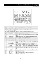
3. Names and functions of each part
Control Panel
No
Name
Description
1
Top screen
Display read temperature in Furnace and error numbers.
2
Bottom screen
Display target temperature and various information.
3
Program setting item display Illuminate one of lamps selected from different settings.
4
Comes on during duration/time
setting and in the Monitoring
mode
Illuminate one of lamps selected from 3(three) different settings.
5
REMOTE Lamp
Illuminate during control via communication
6
ERROR Lamp
Illuminate this Lamp at each error occurred.
7
OPERATE Lamp
lluminate this Lamp during oepration, and flash it during operation standby
mode.
8
HEATER Lamp
Flashes or lights while the heater is live according to the operation amount.
9
EVENT Lamp
lluminate this Lamp at Event Output setting(option).
10
FIXED TEMP Lamp
lluminate while the fixed temperature operation mode is selected.
11
PROGRAM Lamp
lluminate in the Program operation mode.
12
AUTO START Lamp
lluminate in the Auto start mode.
13
AUTO STOP Lamp
lluminate in the Auto stop mode.
14
MODE key
Use at changing Operation Mode among No. 10 thru. No.13(
⑩~⑬
on the
Panel).
15
Controller POWER key
Turn “Idle State”-(Controller is sleeping) or “Standby State”-(Controller is
awaking) of Keys(except
⑱
MENU Key) by pressing and holding this key.
16
DISP key
Keep this key pressed longer to execute the Monitoring function.
This key functions as the back key for setting items while any of setting
menusis displayed.
17
START/STOP key
Use to start sellected operation or to stop working operation.
18
MENU key
Use to set target program, click on/off, output temperature range(option), and
etc.
19
Esc key
Use to abort or get out of working menu without entering and/or editing set
value and items.
20
▲(Up) key
Use to change set value up.
21
▼(Down) key
Use to change set value down.
22
key
Used as the Left key for the setting digits (cursor) during setting.
23
ENTER key
Use to enter set value and items.
▼
Summary of Contents for FP102
Page 67: ...64 12 Wiring diagram FP102 Wiring diagram Dotted line means optional parts ...
Page 68: ...65 12 Wiring diagram FP302 Wiring diagram Dotted line means optional parts ...
Page 69: ...66 12 Wiring diagram FP312 Wiring diagram Dotted line means optional parts ...
Page 70: ...67 12 Wiring diagram FP412 Wiring diagram Dotted line means optional parts ...


