SWINGARM
4-62
• Bearings
Damage/pitting
→
Replace.
EAS23380
INSTALLING THE SWINGARM
1. Lubricate:
• Bearings
• Spacers
• Dust covers
• Pivot shaft
2. Install:
• Bearings “1”
3. Install:
• Swingarm adjusting collar “1”
• Swingarm “2”
• Pivot shaft
• Pivot shaft nut “3”
▼▼▼
▼
▼
▼▼▼
▼
▼
▼▼▼
▼
▼
▼▼▼
▼
▼
▼▼▼
▼
▼
▼▼▼
▼
▼▼▼
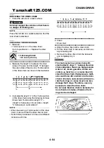
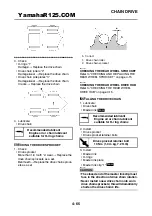
a. Install, and then fully turn in the swingarm ad-
justing collar so that it contacts the frame.
b. Install the swingarm, pivot shaft, washer and
pivot shaft nut.
NOTE:
Temporarily tighten the pivot shaft nut.
c. Turn the swingarm adjusting collar out to
tighten it and so that it contacts the dust cover
on the swingarm.
d. Tighten the pivot shaft nut.
e. Check the swingarm side play.
Refer to “REMOVING THE SWINGARM” on
page 4-61.
▲▲▲
▲
▲
▲▲▲
▲
▲
▲▲▲
▲
▲
▲▲▲
▲
▲
▲▲▲
▲
▲
▲▲▲
▲
▲▲▲
4. Install:
• Rear shock absorber assembly
• Relay arm
• Rear wheel
Refer to “REAR SHOCK ABSORBER AS-
SEMBLY” on page 4-56 and “REAR WHEEL”
on page 4-12.
5. Adjust:
• Drive chain slack
Refer to “ADJUSTING THE DRIVE CHAIN
SLACK” on page 3-21.
Recommended lubricant
Lithium-soap-based grease
Bearing installed depth “a”
5 mm (0.2 in)
2. Swingarm
A. Left side
B. Right side
1
1
a
a
2
A
B
1
T
R
.
.
Pivot shaft nut
81 Nm (8.1 m·kg, 59 ft·lb)
Drive chain slack
30.0–40.0 mm (1.18–1.57 in)
3
1
2
YamahaR125.COM
Summary of Contents for YZF-R125
Page 1: ...5D7 F8197 E0 YAMAHAR125 COM SERVICE MANUAL YZF R125 ...
Page 6: ...YamahaR125 COM ...
Page 8: ...YamahaR125 COM ...
Page 52: ...LUBRICATION SYSTEM CHART AND DIAGRAMS 2 29 1 2 3 4 YamahaR125 COM ...
Page 70: ...CABLE ROUTING 2 47 YamahaR125 COM ...
Page 73: ...YamahaR125 COM ...
Page 102: ...ELECTRICAL SYSTEM 3 29 YamahaR125 COM ...
Page 105: ...YamahaR125 COM ...
Page 172: ...CHAIN DRIVE 4 67 YamahaR125 COM ...
Page 181: ...ENGINE REMOVAL 5 6 2 2 4 1 3 YamahaR125 COM ...
Page 263: ...THROTTLE BODY 7 8 YamahaR125 COM ...
Page 264: ...AIR INDUCTION SYSTEM 7 9 EAS27040 AIR INDUCTION SYSTEM 1 2 3 YamahaR125 COM ...
Page 268: ...AIR INDUCTION SYSTEM 7 13 YamahaR125 COM ...
Page 271: ...YamahaR125 COM ...
Page 283: ...CHARGING SYSTEM 8 12 1 AC magneto 3 Rectifier regulator 4 Main fuse 9 Battery YamahaR125 COM ...
Page 285: ...CHARGING SYSTEM 8 14 YamahaR125 COM ...
Page 295: ...SIGNALING SYSTEM 8 24 YamahaR125 COM ...
Page 299: ...COOLING SYSTEM 8 28 YamahaR125 COM ...
Page 323: ...FUEL INJECTION SYSTEM 8 52 YamahaR125 COM ...
Page 327: ...FUEL PUMP SYSTEM 8 56 YamahaR125 COM ...
Page 353: ...YamahaR125 COM ...
Page 354: ...YamahaR125 COM ...


