FUEL INJECTION SYSTEM
8-20
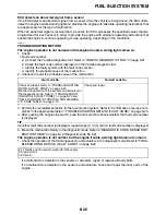
ECU detects an abnormal signal from a sensor
If the ECU detects an abnormal signal from a sensor while the vehicle is being driven, the ECU illumi-
nates the engine trouble warning light and provides the engine with alternate operating instructions that
are appropriate for the type of malfunction.
When an abnormal signal is received from a sensor, the ECU processes the specified values that are
programmed for each sensor in order to provide the engine with alternate operating instructions that
enable the engine to continue operating or stop operating, depending on the conditions.
EAM30353
TROUBLESHOOTING METHOD
The engine operation is not normal and the engine trouble warning light comes on.
1. Check:
•
Fault code number
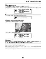
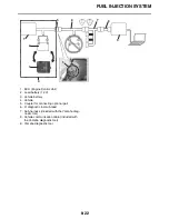
a. Connect the Yamaha diagnostic tool. Refer to “YAMAHA DIAGNOSTIC TOOL” on page 8-21.
b. Check the fault code number displayed on the Yamaha diagnostic tool.
c. Identify the faulty system with the fault code number.
d. Identify the probable cause of the malfunction.
2. Check and repair the probable cause of the malfunction.
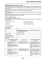
3. Perform the reinstatement action for the fuel injection system. Refer to “Confirmation of service com-
pletion” in the appropriate table in “TROUBLESHOOTING DETAILS (FAULT CODE)” on page 8-23.
4. After pushing the engine stop switch, push the start switch to check whether the fault code number
is displayed.
TIP
If another fault code number is displayed, repeat steps (1) to (4) until no fault code number is displayed.
5. Erase the malfunction history in the diagnostic mode. Refer to “DIAGNOSTIC CODE: SENSOR OP-
ERATION TABLE” on page 9-12 (Diagnostic code No. 62).
The engine operation is not normal, but the engine trouble warning light does not come on.
1. Check the operation of the following sensors and actuators in the diagnostic mode. Refer to “TROU-
BLESHOOTING DETAILS (FAULT CODE)” on page 8-23.
If a malfunction is detected in the sensors or actuators, repair or replace all faulty parts.
If no malfunction is detected in the sensors and actuators, check and repair the inner parts of the
engine.
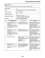
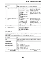
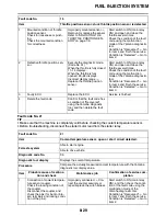
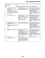
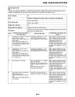
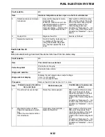
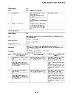
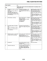
Fault code No.
No fault code No.
Check and repair. Refer to “TROUBLESHOOTING
DETAILS (FAULT CODE)” on page 8-23.
Monitor the operation of the sensors and actuators in
the diagnostic mode. Refer to “TROUBLESHOOT-
ING DETAILS (FAULT CODE)” on page 8-23 and
“SELF-DIAGNOSTIC FUNCTION AND DIAGNOS-
Check and repair.
01: Throttle position sensor signal (throttle angle)
30: Ignition coil
36: Injector
Summary of Contents for YZ 2023 Series
Page 6: ...EAM20162 YAMAHA MOTOR CORPORATION U S A YZ MOTORCYCLE LIMITED WARRANTY...
Page 10: ......
Page 44: ...MOTORCYCLE CARE AND STORAGE 1 32...
Page 61: ...TIGHTENING TORQUES 2 16...
Page 62: ...CABLE ROUTING DIAGRAM 2 17 EAM20152 CABLE ROUTING DIAGRAM Frame and engine left side view...
Page 64: ...CABLE ROUTING DIAGRAM 2 19 Frame and engine right side view...
Page 66: ...CABLE ROUTING DIAGRAM 2 21 Handlebar front view...
Page 68: ...CABLE ROUTING DIAGRAM 2 23 Frame and engine top view...
Page 70: ...CABLE ROUTING DIAGRAM 2 25 Frame and battery top view...
Page 72: ...CABLE ROUTING DIAGRAM 2 27 Rear brake right side view...
Page 74: ...CABLE ROUTING DIAGRAM 2 29...
Page 112: ...ELECTRICAL SYSTEM 3 36...
Page 148: ...REAR BRAKE 4 34 system Refer to BLEEDING THE HYDRAULIC BRAKE SYSTEM on page 3 25...
Page 154: ...HANDLEBAR 4 40 Throttle grip free play 3 0 6 0 mm 0 12 0 24 in...
Page 187: ...INSTALLING THE TRANSMISSION 5 74...
Page 190: ...LUBRICATION SYSTEM CHART AND DIAGRAMS 5 3 1 Oil filter element 2 Oil pump...
Page 191: ...LUBRICATION SYSTEM CHART AND DIAGRAMS 5 4 1 Intake camshaft 2 Exhaust camshaft...
Page 264: ...TRANSMISSION 5 77...
Page 274: ...WATER PUMP 6 9...
Page 284: ...THROTTLE BODY 7 9...
Page 287: ......
Page 288: ...IGNITION SYSTEM 8 1 EAM20142 IGNITION SYSTEM EAM30277 CIRCUIT DIAGRAM...
Page 292: ...ELECTRIC STARTING SYSTEM 8 5 EAM20143 ELECTRIC STARTING SYSTEM EAM30279 CIRCUIT DIAGRAM...
Page 296: ...CHARGING SYSTEM 8 9 EAM20144 CHARGING SYSTEM EAM30282 CIRCUIT DIAGRAM...
Page 299: ...CHARGING SYSTEM 8 12...
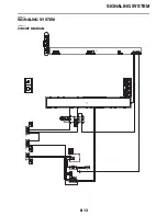
Page 300: ...SIGNALING SYSTEM 8 13 EAM20154 SIGNALING SYSTEM EAM30348 CIRCUIT DIAGRAM...
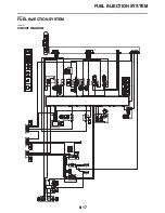
Page 304: ...FUEL INJECTION SYSTEM 8 17 EAM20145 FUEL INJECTION SYSTEM EAM30284 CIRCUIT DIAGRAM...
Page 329: ...FUEL INJECTION SYSTEM 8 42...
Page 330: ...FUEL PUMP SYSTEM 8 43 EAM20146 FUEL PUMP SYSTEM EAM30287 CIRCUIT DIAGRAM...
Page 362: ...SELF DIAGNOSTIC FUNCTION AND DIAGNOSTIC CODE TABLE 9 15...
Page 372: ...CHASSIS 10 9...
Page 374: ......
Page 376: ......
Page 377: ...YZ250FXP 2023 WIRING DIAGRAM BAJ 2819U 13_WD indd 1 2022 04 01 9 58 37...
Page 378: ...YZ250FXP 2023 WIRING DIAGRAM BAJ 2819U 13_WD indd 2 2022 04 01 9 58 37...


