ELECTRICAL COMPONENTS
8-65
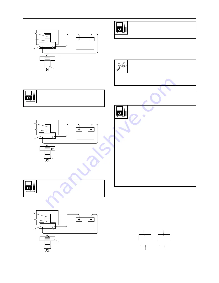
Main relay
Starting circuit cut-off relay
Radiator fan motor relay
EASB29B352
CHECKING THE DIODE
1. Check:
• Diode
Out of specification
Replace.
TIP
The digital circuit tester readings are shown in
the following table.
▼▼▼▼▼▼▼▼▼▼▼▼▼▼▼▼▼▼▼▼▼▼▼▼▼▼▼▼▼▼▼▼
a. Disconnect the diode from the wire harness.
b. Connect the digital circuit tester (
) to the di-
ode coupler as shown.
c. Check the diode for continuity.
d. Check the diode for no continuity.
▲▲▲▲▲▲▲▲▲▲▲▲▲▲▲▲▲▲▲▲▲▲▲▲▲▲▲▲▲▲▲▲
1. Positive battery terminal
2. Negative battery terminal
3. Positive tester probe
4. Negative tester probe
Result
Continuity
(between “3” to “4”)
1. Positive battery terminal
2. Negative battery terminal
3. Positive tester probe
4. Negative tester probe
Result
Continuity
(between “3” to “4”)
1. Positive battery terminal
2. Negative battery terminal
3. Positive tester probe
4. Negative tester probe
1
2
3
4
L/R
Br
R
R,R/W
1
2
3
4
G/B
L/B
L/G,L/W
1
2
3
4
P/L
R/L
R/W
Br,R/W
Result
Continuity
(between “3” to “4”)
Digital circuit tester (CD732)
90890-03243
Model 88 Multimeter with
tachometer
YU-A1927
No continuity
Tester positive lead
Sky blue
“1”
Tester negative lead
Green/
Black “2”
Continuity
Tester positive lead
Green/
Black “2”
Tester negative lead
Sky blue
“1”
No continuity
Tester positive lead
Red “3”
Tester negative lead
Red/Blue
“4”
Continuity
Tester positive lead
Red/Blue
“4”
Tester negative lead
Red “3”
2
1
4
3
R
Sb
G/B
R/L
Summary of Contents for YZ 2018 Series
Page 6: ...EASB916006 YAMAHA MOTOR CORPORATION U S A YZ MOTORCYCLE LIMITED WARRANTY...
Page 10: ......
Page 40: ...MOTORCYCLE CARE AND STORAGE 1 28...
Page 64: ...LUBRICATION SYSTEM CHART AND DIAGRAMS 2 23...
Page 66: ...LUBRICATION SYSTEM CHART AND DIAGRAMS 2 25...
Page 68: ...LUBRICATION SYSTEM CHART AND DIAGRAMS 2 27...
Page 70: ...CABLE ROUTING DIAGRAM 2 29 EASB29B065 CABLE ROUTING DIAGRAM...
Page 72: ...CABLE ROUTING DIAGRAM 2 31...
Page 74: ...CABLE ROUTING DIAGRAM 2 33...
Page 76: ...CABLE ROUTING DIAGRAM 2 35...
Page 78: ...CABLE ROUTING DIAGRAM 2 37...
Page 80: ...CABLE ROUTING DIAGRAM 2 39...
Page 82: ...CABLE ROUTING DIAGRAM 2 41...
Page 84: ...CABLE ROUTING DIAGRAM 2 43...
Page 255: ...OIL PUMP AND BALANCER GEAR 5 58 a 2 10 b 2 9 1 b 5 3 a 4 10 5 9 3 E c d 6 7 8 8 b 6...
Page 276: ...TRANSMISSION 5 79...
Page 290: ...FUEL TANK 7 5 A Left B Right 1 1 A 0 mm 0 in B 1 1 15 mm 0 59 in...
Page 296: ...THROTTLE BODY 7 11...
Page 299: ......
Page 313: ...CHARGING SYSTEM 8 14...
Page 321: ...COOLING SYSTEM For JPN 8 22...
Page 351: ...FUEL PUMP SYSTEM 8 52 EASB29B345...
Page 352: ...ELECTRICAL COMPONENTS 8 53 ELECTRICAL COMPONENTS EASB29B346 9 10 11 1 3 2 4 5 6 7 8...
Page 354: ...ELECTRICAL COMPONENTS 8 55 11 10 9 2 3 1 6 7 8 4 5...
Page 356: ...ELECTRICAL COMPONENTS 8 57 EASB29B347 CHECKING THE SWITCHES 4 1 3 2 B B Sb B B B B B B B B...
Page 372: ...ELECTRICAL COMPONENTS 8 73 c Measure the fuel injector resistance...


