ELECTRIC STARTER
5-37
7. Check:
• Gear teeth
Damage/wear
Replace the starter motor.
8. Check:
• Oil seal
Damage/wear
Replace the defective part
(s).
EASB29B237
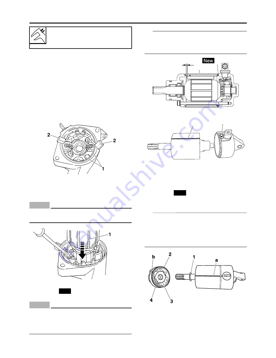
ASSEMBLING THE STARTER MOTOR
1. Install:
• Brush spring “1”
• Brush “2”
2. Install:
• Armature assembly “1”
Install while holding down the brush using a
thin screw driver.
ECA
NOTICE
Be careful not to damage the brush during
installation.
3. Install:
• O-ring “1”
• Starter motor yoke “2”
ECA
NOTICE
Install the part that has a smaller step differ-
ence “a” with the magnet of the starter mo-
tor yoke facing the starter motor front
cover.
TIP
Align the match mark “a” on the starter motor
yoke with the match mark “b” on the starter mo-
tor rear cover.
4. Install:
• Circlip
• Plain washer “1”
• O-ring “2”
• Washer (starter motor front cover) “3”
• Starter motor front cover “4”
TIP
• For installation, align the projections on the
washer with the slots in the front cover.
• Align the match mark “a” on the starter motor
yoke with the match mark “b” on the starter
motor front cover.
Brush spring force
3.92–5.88 N (400–600 gf, 14.11–
21.17 oz)
New
a
1
2
a
b
New
Summary of Contents for YZ 2018 Series
Page 6: ...EASB916006 YAMAHA MOTOR CORPORATION U S A YZ MOTORCYCLE LIMITED WARRANTY...
Page 10: ......
Page 40: ...MOTORCYCLE CARE AND STORAGE 1 28...
Page 64: ...LUBRICATION SYSTEM CHART AND DIAGRAMS 2 23...
Page 66: ...LUBRICATION SYSTEM CHART AND DIAGRAMS 2 25...
Page 68: ...LUBRICATION SYSTEM CHART AND DIAGRAMS 2 27...
Page 70: ...CABLE ROUTING DIAGRAM 2 29 EASB29B065 CABLE ROUTING DIAGRAM...
Page 72: ...CABLE ROUTING DIAGRAM 2 31...
Page 74: ...CABLE ROUTING DIAGRAM 2 33...
Page 76: ...CABLE ROUTING DIAGRAM 2 35...
Page 78: ...CABLE ROUTING DIAGRAM 2 37...
Page 80: ...CABLE ROUTING DIAGRAM 2 39...
Page 82: ...CABLE ROUTING DIAGRAM 2 41...
Page 84: ...CABLE ROUTING DIAGRAM 2 43...
Page 255: ...OIL PUMP AND BALANCER GEAR 5 58 a 2 10 b 2 9 1 b 5 3 a 4 10 5 9 3 E c d 6 7 8 8 b 6...
Page 276: ...TRANSMISSION 5 79...
Page 290: ...FUEL TANK 7 5 A Left B Right 1 1 A 0 mm 0 in B 1 1 15 mm 0 59 in...
Page 296: ...THROTTLE BODY 7 11...
Page 299: ......
Page 313: ...CHARGING SYSTEM 8 14...
Page 321: ...COOLING SYSTEM For JPN 8 22...
Page 351: ...FUEL PUMP SYSTEM 8 52 EASB29B345...
Page 352: ...ELECTRICAL COMPONENTS 8 53 ELECTRICAL COMPONENTS EASB29B346 9 10 11 1 3 2 4 5 6 7 8...
Page 354: ...ELECTRICAL COMPONENTS 8 55 11 10 9 2 3 1 6 7 8 4 5...
Page 356: ...ELECTRICAL COMPONENTS 8 57 EASB29B347 CHECKING THE SWITCHES 4 1 3 2 B B Sb B B B B B B B B...
Page 372: ...ELECTRICAL COMPONENTS 8 73 c Measure the fuel injector resistance...


