background image

 En

 7

INTRODUCTION

Part names and functions

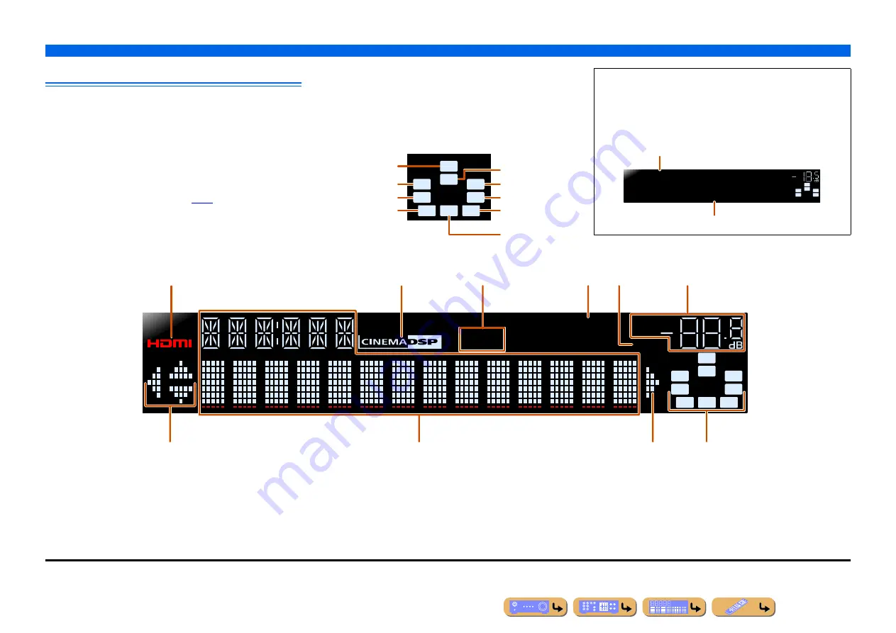
Front panel display

a

HDMI indicator

Lights up during normal HDMI communication when any of the 
HDMI 1-4 inputs are selected.

b

CINEMA DSP indicator

Lights up when a sound field effect that uses CINEMA DSP 
technology is selected.

c

Tuner indicator

Lights up when receiving an FM/AM broadcast.

d

SLEEP indicator

Lights up when the sleep timer is on (

p. 8

).

e

MUTE indicator

Flashes when audio is muted.

f

VOLUME indicator

Displays the current volume level.

g

Cursor indicators

Light up if corresponding cursors on the remote control are available 
for operations.

h

Multi information display

Displays a range of information on menu items and settings.

i

Speaker indicators

Indicate speaker terminals from which signals are output.

SW

C

L

R

SL

SR

SBL

SBR

SB

Front speaker L

Surround speaker L

Subwoofer

Front speaker R

Surround speaker R

Center speaker

Surround back

speaker L

Surround back 
speaker R

Surround back 
speaker

J

1

Changing the front panel display

The front panel can display sound field programs and surround 
decoder names as well as the active input source. 
Press 

f

INFO

 repeatedly to cycle through input source 


sound field program 

 surround decoder in order.

J

2

SW
C

L
SL

SR

R

Straight

HDMI1

VOL.

Input source name

Sound field program (DSP program)

STEREO

SLEEP

VOL.

TUNED

SW

C

L

R

SL

SR

MUTE

SBL

SBR

SB

a

b

c

d

f

e

g

h

i

g

J

1 :

“SB” is displayed when using a 6.1-channel configuration only.

J

2 :

While selecting a tuner input, the FM/AM frequency is displayed instead of the input source.

Summary of Contents for YHT-693

Page 1: ...Owner s Manual AV Receiver English ...

Page 2: ...eiver 42 Pairing Bluetooth components 42 Using Bluetooth components 43 SETUP Configuring the settings specific for each input source Option menu 44 Option menu display and setup 44 Option menu items 44 Setting various functions Setup menu 48 Setup menu display and settings 48 Setup menu items 49 Manages settings for speakers 49 Setting the audio output function of this unit 53 Setting HDMI functio...

Page 3: ...HDMI compatible device such as TVs HDMI Control function 67 Listening to TV audio with single HDMI cable connection Audio Return Channel function 69 FM AM tuner FM AM broadcast listening 34 Simple preset tuning 35 U K and Europe models Radio Data System tuning 37 U K and Europe models Automatic traffic information reception 38 Changing FM mode Stereo Monaural 35 Asia and General models only Changi...

Page 4: ...nt panel Rear panel Front panel display Remote control Attaching the VIDEO AUX input cover supplied To protect against dust attach the supplied VIDEO AUX input cover to the VIDEO AUX jacks when you do not use the jacks To remove the cover push the left section of it Attach the cover PUSH Remove the cover Installing batteries in the remote control When inserting batteries in the remote control remo...

Page 5: ...k Press either the left or right key repeatedly to cycle through the input sources in order n SCENE Switches the input source and the sound field program with a single button p 29 When this unit is in standby mode press this key to switch on o TONE CONTROL Adjusts high frequency low frequency output of speakers headphones p 28 p PROGRAM l h Switches between the sound field effect sound field progr...

Page 6: ...um of 7 1 channels by connecting an external amplifier p 11 l SUBWOOFER jack For connecting a subwoofer with a built in amplifier p 13 m VOLTAGE SELECTOR Asia and General models only Select the switch position according to your local voltage Refer to Quick Reference Guide n Power cable For connecting this unit to an AC wall outlet VIDEO jack For connecting a TV capable of receiving video input and...

Page 7: ... menu items and settings i Speaker indicators Indicate speaker terminals from which signals are output SW C L R SL SR SBL SBR SB Front speaker L Surround speaker L Subwoofer Front speaker R Surround speaker R Center speaker Surround back speaker L Surround back speaker R Surround back speaker J1 Changing the front panel display The front panel can display sound field programs and surround decoder ...

Page 8: ...tedly to set the time for the sleep timer function The SLEEP indicator p 7 lights up when the sleep timer is on q OPTION Displays the Option menu for each input source p 44 r VOLUME Adjusts the volume level p 28 s MUTE Turns the mute function of the sound output on and off p 28 RECEIVER SCENE OPTION SETUP RETURN VOLUME ENHANCER SUR DECODE STRAIGHT DIRECT HDMI AV AUDIO TRANSMIT SLEEP 1 2 3 4 1 2 3 ...

Page 9: ...ear area is output Surround speaker layout Place the speakers at the rear of the room on the left and right sides facing the listening position They should be placed between 60 degrees and 80 degrees from the listening position and with the speaker tops at a height of 1 5 1 8 m from the floor Surround back left and right speakers Outputs the rear effect When used with 6 1ch sound sound from the le...

Page 10: ...R Subwoofer Center speaker Surround speaker L Surround speaker R CRT monitors We recommend that you use magnetically shielded speakers to avoid video distortion especially for the front and center speakers near the screen If your screen still gets interference from magnetically shielded speakers move the speakers farther away from your TV 60q 60q 80q 80q Front speaker L Front speaker R Subwoofer C...

Page 11: ...mizer or Speaker Setup of the Setup menu p 23 CAUTION Remove the AC power cable of this unit from the power outlet before connecting the speakers Generally speaker cables consist of two parallel insulated cables One of these cables is a different color or has a line running along it to indicate different polarity Insert the different colored or lined cable into the positive red terminal on this un...

Page 12: ... turns on when the settings you made has been configured Connecting speakers 1 Remove approximately 10 mm of insulation from the ends of the speaker cables and twist the bare wires of the cables together firmly so that they will not cause short circuits 2 Loosen the speaker terminals 3 Insert the bare wire of the speaker cable into the gap on the side of the terminal 4 Tighten the terminal PHONES ...

Page 13: ...er input jack to the SUBWOOFER jack on this unit with an audio pin cable 2 Set the subwoofer volume as follows Volume Set to approximately half volume or slightly less than half Crossover frequency if available Set to maximum VOLUME MIN MAX CROSSOVER HIGH CUT MIN MAX Subwoofer examples ...

Page 14: ...nce red PR Use component video pin cables with three plugs VIDEO jack This jack transmits conventional analog video signals Use video pin cables HDMI cable Component video pin cable Video pin cable OPTICAL jacks These jacks transmit optical digital audio signals Use fiber optic cables for optical digital audio signals COAXIAL jacks These jacks transmit coaxial digital audio signals Use pin cables ...

Page 15: ... ARC MONITOR OUT COMPONENT VIDEO VIDEO PR PB Y COMPONENT VIDEO PR PB Y BD DVD HDMI 2 HDMI 1 HDM VIDEO DOCK ANTENNA FM 75ǡ GND AM HDMI OUT jack COMPONENT VIDEO jacks MONITOR OUT VIDEO jack MONITOR OUT COMPONENT VIDEO HDMI VIDEO COMPONENT VIDEO HDMI VIDEO Input Output TV HDMI input Component video input Video input Use a 19 pin HDMI cable with the HDMI logo We recommend using a cable less than 5 0 m...

Page 16: ...V 2 AV 3 AV 4 AV 5 AV 6 AUDIO 1 AUDIO 2 COAXIAL COAXIAL CD BD DVD HDMI 2 HDMI 1 HDMI OUT AV OUT VIDEO DOCK ARC ANTENNA FM 75ǡ GND AM MONITO COMPONENT VIDEO PR PB Y VIDEO V V Video input TV When using other TVs To transmit sound from the TV to this unit connect its AV1 6 or AUDIO1 2 jacks to the TV s audio output jacks Depending on the connection on TV connect the TV s audio output to the AV1 6 or ...

Page 17: ...DEO PR PB Y OPTICAL OPTICAL TV AV 1 AV 2 AV 3 AV 4 AV 5 AV 6 AUDIO 1 AUDIO 2 COAXIAL COAXIAL CD FRONT HDMI OUT AV OUT AUDIO OUT VIDEO DOCK ARC ANTENNA FM 75ǡ GND AM MONITOR OUT COMPONENT VIDEO VIDEO PR PB Y HDMI HDMI HDMI HDMI output BD DVD player Receiving video signals from the HDMI jack and audio signals from a jack other than HDMI This unit can use the AV1 6 or AUDIO1 2 input jacks to receive ...

Page 18: ...CK ARC ANTENNA FM 75ǡ GND AM MONITOR OUT COMPONENT VIDEO VIDEO PR PB Y COMPONENT VIDEO COAXIAL Y PR C PB Y PR PB C Component video Audio Coaxial output BD DVD player Component connections to analog audio output devices You can use the video input from the AV1 2 jacks in combination with the audio input from other AV inputs or AUDIO1 2 When connecting these devices select the AV input jacks or the ...

Page 19: ...L AV 1 AV 2 AV 3 AV 5 AV 6 AUDIO 1 AUDIO 2 COAXIAL COAXIAL CD BD DVD HDMI 2 HDMI 1 HDMI OUT AV OUT VIDEO DOCK ARC ANTENNA FM 75ǡ GND AM MONITOR OUT COMPONENT VIDEO VIDEO PR PB Y VIDEO OPTICAL V V O O Video Audio Optical output BD DVD player COAXIAL CD VIDEO COMPONENT VIDEO PR PB Y OPTICAL OPTICAL TV AV 1 AV 2 AV 4 AV 5 AV 6 AUDIO 1 AUDIO 2 COAXIAL BD DVD HDMI 2 HDMI 1 HDMI OUT AV OUT DOCK ARC ANTE...

Page 20: ... FM 75ǡ GND AM MONITOR OUT COMPONENT VIDEO VIDEO PR PB Y AUDIO R L R L Audio output CD player OPTICAL OPTICAL COMPONENT VIDEO PR PB Y AV 2 AV 3 AV 5 AV 6 AUDIO 1 AUDIO 2 COAXIAL COAXIAL CD BD DVD HDMI 2 HDMI 1 HDMI OUT AV OUT VIDEO DOCK ARC ANTENNA FM 75ǡ GND AM MONITOR OUT COMPONENT VIDEO VIDEO PR PB Y O O OPTICAL CD player Audio Optical output We recommend connecting audio devices with an coaxia...

Page 21: ...he AUDIO OUT jacks Connect this jack to the external component s analog audio input jacks Be sure to turn down the volume when connecting this unit and the other devices When external components are connected to both the PORTABLE jack and the AUDIO jacks the sound output from the PORTABLE jack is transmitted VIDEO AUX ST RAIGHT RADIO VIDEO AUDIO PO RTABLE L R V R L L R V AUDIO VIDEO AUDIO OUT Audi...

Page 22: ...ill connected Connecting the GND jack can reduce noise Connect the jack to a store bought ground bar or copper plate with a vinyl covered wire and bury this new attachment in moist ground The GND jack is not to be connected to the ground socket of an electrical outlet ANTENNA FM 75ǡ GND AM NENT O BD DVD HDMI 2 HDMI 1 HDMI 3 HDMI OUT VIDEO DOCK MONITOR OUT COMPONENT VIDEO VIDEO PR PB Y Indoor FM an...

Page 23: ...rs on the front panel display and then changes to display the following J2 Set up the speaker parameters automatically YPAO When you use YPAO a test tone will be output from the speakers for approximately 3 minutes and acoustic measuring will be performed When using YPAO be careful of the following The test tone is output at high volume Please refrain from using this function at night when it may ...

Page 24: ...e again Front Sets the characteristics of each speaker to match the front speakers Choose this when the front speakers are of significantly higher quality than the other speakers This completes preparations To achieve more accurate results be careful of the following when measuring Measuring will take approximately 3 minutes Keep the room as quiet as possible during measurement Wait in the corner ...

Page 25: ... to resolve the problem You can confirm the speaker that has the problem on the TV screen Confirm the warning message Press jENTER once When multiple warning messages exist Press jENTER to confirm the warning message and use jCursor D E to display other warning messages When applying the results of measurement If an warning message is displayed press jENTER to switch display use jCursor D E to sel...

Page 26: ...ain in quiet surroundings Turn off any devices in the room that may be emitting noise or place them further away from the YPAO microphone When this message is displayed selecting Proceed will allow you to continue measuring However we recommend resolving the problem and measuring again as continuing measurement without doing so will not give accurate results E 6 CHECK SUR Even though surround left...

Page 27: ...s normally even this message appears W 2 DISTANCE The speakers displayed are separated from the listening position by more than 24 m and cannot be adjusted correctly Install the speakers with 24 m of the listening point W 3 LEVEL The difference each channel is too loud or too low and cannot be adjusted correctly Check that all speakers are installed in the same surroundings Check that the speaker ...

Page 28: ...tedly to select Treble or Bass The current setting is displayed on the front panel display 2 Press PROGRAM l h to adjust the output level in those frequency ranges The display returns to the previous display soon after you release the key Basic playback procedure dInput selector rVOLUME sMUTE VOLUME HDMI AV AUDIO 1 2 3 4 1 2 3 4 1 2 5 6 V AUX TUNER MUTE DOCK RECEIVER SCENE OPTION SETUP RETURN ENHA...

Page 29: ...aying back rather than relying on the name or explanation of the program Changing input settings with a single key SCENE function dInput selector gSound selection keys hSCENE SCENE ENHANCER SUR DECODE STRAIGHT DIRECT HDMI AV AUDIO 1 2 3 4 1 2 3 4 1 2 5 6 V AUX TUNER MOVIE MUSIC STEREO BD DVD TV CD RADIO DOCK RECEIVER OPTION SETUP RETURN VOLUME TRANSMIT SLEEP FM INFO MEMORY AM PRESET TUNING MUTE EN...

Page 30: ...s for the playback of CD and BD DVD sources 2 channel sources such as CD Stereo sound plays back through the front speakers Multi channel sources such as BD DVD Playback channels other than the front channels in the playback source are mixed with the front channels and played back through the front speakers Press gSTEREO repeatedly to select 2ch Stereo gSound selection keys gMOVIE gMUSIC gSTEREO g...

Page 31: ...ENE OPTION SETUP RETURN VOLUME ENHANCER SUR DECODE STRAIGHT HDMI AV AUDIO TRANSMIT SLEEP 1 2 3 4 1 2 3 4 1 2 5 6 V AUX TUNER FM INFO MEMORY AM PRESET TUNING MOVIE MUSIC STEREO BD DVD TV CD RADIO MUTE ENTER 7 8 5 6 9 0 10 1 2 3 4 REC ENT TV TVVOL TV CH TOP MENU POP UP MENU DISPLAY SOURCE CODE SET INPUT MUTE DOCK A B g To disable direct mode press gDIRECT again VOL L R Direct J1 However Virtual CINE...

Page 32: ...eling In sports broadcasts the voices of the commentator and sportscaster are positioned clearly at the center while the atmosphere of the stadium expands in an optimal space to offer the listeners a feeling of presence in the stadium Action Game This sound field is suitable for action games such as car racing and FPS games It uses reflection data that limits the effects range per channel in order...

Page 33: ...ght Enhancer Use this program to restore the original depth and dynamics of 2 channel or multi channel to compression audio 7ch Enhancer Use this program to playback compression artifacts in 7 channel stereo q Pro Logic Reproduces sound using the Dolby Pro Logic decoder This is suitable for all kinds of sound sources q PLIIx Movie q PLII Movie Reproduces sound using the Dolby Pro Logic IIx or Dolb...

Page 34: ...s only The factory pre set FM AM tuner frequency steps are 9 kHz for AM and 50 kHz for FM Carry out the following settings and select the frequency steps suitable for your listening environment 1 Switch this unit to the standby mode 2 Press A while pressing and holding STRAIGHT on the front panel Release the keys when ADVANCED SETUP is displayed on the front panel display After approximately a few...

Page 35: ...CE CODE SET INPUT MUTE DOCK A B q l j e d Entering a frequency number In normal tuning mode use the lNumeric keys on the remote control to enter a frequency Leave the decimal point out when entering a number J2 For example enter as follows to select a station on 98 50MHz STEREO TUNED SW C L SL SR R FM 98 50MHz STEREO TUNED VOL Lights up when receiving a broadcast from a station Lights up when rece...

Page 36: ...l display After a small wait the preset number that the station has been registered to will appear Press ePRESET F G to select the preset to register the station to and then press eMEMORY to register eMEMORY ePRESET F G jCursor B C jENTER jRETURN RETURN MEMORY PRESET ENTER RECEIVER SCENE OPTION SETUP VOLUME ENHANCER SUR DECODE STRAIGHT DIRECT HDMI AV AUDIO TRANSMIT SLEEP 1 2 3 4 1 2 3 4 1 2 5 6 V ...

Page 37: ...UNER ePRESET F G jCursor B C jENTER jRETURN lNumeric keys qOPTION OPTION RETURN TUNER PRESET ENTER 7 8 5 6 9 0 10 1 2 3 4 ENT RECEIVER SCENE SETUP VOLUME ENHANCER SUR DECODE STRAIGHT DIRECT HDMI AV AUDIO TRANSMIT SLEEP 1 2 3 4 1 2 3 4 1 2 5 6 V AUX FM INFO MEMORY AM TUNING MOVIE MUSIC STEREO BD DVD TV CD RADIO MUTE REC TV TVVOL TV CH TOP MENU POP UP MENU DISPLAY SOURCE CODE SET INPUT MUTE DOCK A B...

Page 38: ...Radio Data System program currently being received Clock Time Displays the current time DSP Program Displays the currently selected sound field program Audio Decoder Displays the currently selected surround decoder Program Service Program Type Radio Text Clock Time DSP Program Audio Decoder Frequency display Program Service Program Type Radio Text and Clock Type do not appear when the radio statio...

Page 39: ...t while viewing the menu displayed on the iPod iPhone screen Menu browse mode Plays the iPod iPhone while viewing the menu displayed on the front panel display Playing back tunes from your iPod iPhone iPod touch iPod Click and Wheel including iPod classic iPod nano iPod mini iPhone iPhone 3G and iPhone 3GS are supported As of March 2010 When connecting an iPhone please use a YDS 12 Some features m...

Page 40: ...ve the cursor up and down to different fields jCursor D E Return to the previous menu or enter the menu you have selected jENTER Enter the selected menu kDISPLAY Switches between simple play mode or menu browse mode k w Searches backwards while held down k f Searches forwards while held down k b Skip to the beginning of the currently playing song Pressing repeatedly skips one song backwards with e...

Page 41: ...Albums Plays Albums back in random order Off Does not play back songs or albums repeatedly One Plays a Song back repeatedly All When all Songs have completed playback returns to the start and repeats playback To disable Shuffle Repeat playback redo the above steps and return settings to Off To charge the iPod iPhone when this unit is in standby mode If you connect an iPod iPhone to the iPod univer...

Page 42: ...omponent for the first time you must first pair the devices register the Bluetooth components When establishing a wireless connection you must carry out pairing on both this unit and on the Bluetooth component dDOCK eMEMORY jCursor B C jENTER jRETURN qOPTION OPTION RETURN MEMORY ENTER DOCK RECEIVER SCENE SETUP VOLUME ENHANCER SUR DECODE STRAIGHT DIRECT HDMI AV AUDIO TRANSMIT SLEEP 1 2 3 4 1 2 3 4 ...

Page 43: ... STEREO BD DVD TV CD RADIO MUTE 7 8 5 6 9 0 10 1 2 3 4 REC ENT TV TVVOL TV CH TOP MENU POP UP MENU DISPLAY SOURCE CODE SET INPUT MUTE A B q j d Depending on Bluetooth components a wireless connection is established automatically or by operating the Bluetooth components In that case it is not necessary to carry out the following procedure Not found is displayed when there is an error connecting Che...

Page 44: ...ut selector jCursor B C D E jENTER jRETURN qOPTION OPTION RETURN HDMI AV AUDIO 1 2 3 4 1 2 3 4 1 2 5 6 V AUX TUNER ENTER DOCK RECEIVER SCENE SETUP VOLUME ENHANCER SUR DECODE STRAIGHT DIRECT TRANSMIT SLEEP FM INFO MEMORY AM PRESET TUNING MOVIE MUSIC STEREO BD DVD TV CD RADIO MUTE 7 8 5 6 9 0 10 1 2 3 4 REC ENT TV TVVOL TV CH TOP MENU POP UP MENU DISPLAY SOURCE CODE SET INPUT MUTE A B q j d SW C L S...

Page 45: ...t of the input audio DTS Selects DTS signals only Other input signals are not reproduced EXTD Surround Auto Default Automatically selects the most suitable decoder if a flag for reproducing surround back channel is present and reproduces the signals in 6 1 or 7 1 channel q PLIIx Movie Always reproduces signals in 7 1 channel using the Dolby Pro Logic IIx Movie decoder whether or not surround back ...

Page 46: ...he selected input SW C L SL SR R Audio AV1 HDMI1 VOL Assignable audio input jacks Inputs that change the audio source For details of settings refer to Receiving video signals from the HDMI jack and audio signals from a jack other than HDMI p 17 and Component connections to analog audio output devices p 18 To return audio inputs to their previous settings display this item again and select the orig...

Page 47: ...rches for traffic information with the Radio Data System p 38 Charging an iPod iPhone in standby mode Input source DOCK iPod Charges an iPod iPhone stationed in the iPod universal dock while the receiver is in standby mode p 41 Shuffle playback with iPod iPhone Input source DOCK iPod Changes the shuffle playback style on iPod p 41 Repeat playback with iPod iPhone Input source DOCK iPod Changes the...

Page 48: ... HDMI AV AUDIO TRANSMIT SLEEP 1 2 3 4 1 2 3 4 1 2 5 6 V AUX TUNER FM INFO MEMORY AM PRESET TUNING MOVIE MUSIC STEREO BD DVD TV CD RADIO MUTE 7 8 5 6 9 0 10 1 2 3 4 REC ENT TV TVVOL TV CH TOP MENU POP UP MENU DISPLAY SOURCE CODE SET INPUT MUTE DOCK A B j i Speaker Setup Set parameters for speakers such as speaker status and volume adjustment for each speaker Sound Setup Set functions related to aud...

Page 49: ...o the listening point Equalizer Selects an equalizer to adjust speaker output characteristics Test Tone Generates test tones SW C L SL SR R Speaker Setup SETUP VOL Config In the Config submenu you can select the speaker size characteristic Large or Small Select the size sound reproduction capacity that matches your speakers When speaker size is set to Small low frequency components of the speakers...

Page 50: ...even if that speaker is connected When set to None the sound field programs will change to Virtual CINEMA DSP mode None Default Select this when no surround back speakers are connected SMLx1 Select when one small surround back speaker is connected SMLx2 Select when two small surround back speakers are connected LRGx1 Select when one large surround back speaker is connected LRGx2 Select when two la...

Page 51: ...J1 Surround back SWFR Subwoofer Adjustable range 10 0 dB to 10 0 dB Default setting 0 dB FL FR SWFR 1 0 dB C SL SR SBL SBR SB Adjustment increments 0 5 dB Distance Unit Selects the distance unit meters or feet Front L Front speaker L Front R Front speaker R Center Center speaker Sur L Surround speaker L Sur R Surround speaker R Sur B L Surround back speaker L Sur B R Surround back speaker R Sur B ...

Page 52: ... the Setup menu SW C L SL SR R 63Hz GEQ VOL Frequency band Setting the volume level for the selected frequency Frequency range 63 Hz 160 Hz 400 Hz 1 kHz 2 5 kHz 6 3 kHz 16 kHz Adjustable range 6 0 dB to 0 dB to 6 0 dB Default setting 0 dB Adjustment increments 0 5 dB You can use jCursor B C to select another frequency or return to step 2 Repeat steps 2 3 to adjust the tone to your liking Test Tone...

Page 53: ... Lipsync Adjusts the delay between video and audio output Adaptive DRC Auto adjusting the sound level to make even low volumes more audible D Range Selects the dynamic range adjustment method for Dolby Digital and DTS playback Max Volume Sets the maximum volume for this receiver Init Volume Sets the initial volume for when this receiver is turned on SW C L SL SR R Sound Setup SETUP VOL Lipsync Off...

Page 54: ...nal information STD Adjusts the dynamic range for optimum volume for regular home use Max Default Produces audio without adjusting the dynamic range Max Volume Adjustable range 30 0 dB to 15 0 dB 16 5 dB Maximum volume Default setting 16 5 dB Adjustment increments 5 0 dB Init Volume Adjustable range Off Mute 80 dB to 16 5 dB Default setting Off Adjustment increments 0 5 dB Control Turns the HDMI C...

Page 55: ... J1 If this unit is connected to HDMI devices that do not support the HDMI Control function these functions will not operate TVAudio AV1 to AV6 Assigns any of the AV1 6 input source for the audio input from the TV AUDIO1 AUDIO2 Assigns AUDIO1 or AUDIO2 input source for the audio input from the TV Default setting AV4 TVAudio is only displayed with the HDMI Control function Control is set to On Plea...

Page 56: ...selected the external component outputs an audio format compatible with this unit TV Outputs audio through a TV only When this setting is selected the external component outputs an audio format compatible with the TV J1 Amp TV Outputs audio from the TV and this unit When this setting is selected the external component outputs an audio format compatible with this unit and TV Audio is only displayed...

Page 57: ...W C L SL SR R Func Setup SETUP VOL SW C L SL SR R HDMI1 HDMI1 VOL Renaming the input source 2 Select the input source that you want to rename using jCursor B C 3 Use jCursor D E to select a new name from the following templates 4 Confirm the new display name by pressing jRETURN Press iSETUP to exit the Setup menu To cancel a name change select the original name and then press jRETURN to exit renam...

Page 58: ...o prevent careless changes being made to the settings on Setup menu AutoPowerDown Off Default Auto Power Down function is disabled 4hours Goes into standby mode when you have not operated this unit for four hours 8hours Goes into standby mode when you have not operated this unit for eight hours 12hours Goes into standby mode when you have not operated this unit for twelve hours This unit starts a ...

Page 59: ...SUR DECODE STRAIGHT DIRECT HDMI AV AUDIO TRANSMIT SLEEP 1 2 3 4 1 2 3 4 1 2 5 6 V AUX TUNER FM INFO MEMORY AM PRESET TUNING MOVIE MUSIC STEREO BD DVD TV CD RADIO MUTE 7 8 5 6 9 0 10 1 2 3 4 REC ENT TV TVVOL TV CH TOP MENU POP UP MENU DISPLAY SOURCE CODE SET INPUT MUTE DOCK A B j i When there are multiple parameters in the sound field program you are configuring repeat step 4 as necessary to change...

Page 60: ...olby Pro Logic II Movie decoder Neo 6 Cinema Selects the Neo 6 Cinema decoder DSP Level Adjustable range 6 dB to 0 dB to 3 dB Default setting 0 dB Adjust DSP Level as follows The effect sound is too soft There are no differences between effects of the sound field programs Increase the effect level The sound is dull The sound field effect is added too much Reduce the effect level Direct Auto Defaul...

Page 61: ...justs the difference in level between the front sound field and the surround sound field You can adjust the difference in level created by the software being played back to obtain the preferred sound balance The surround sound gets stronger as you make the value more negative and the front sound gets stronger as you make the value more positive When Neo 6 Music is selected Adjusts the front left a...

Page 62: ...DOCK A B RECEIVER SCENE VOLUME ENHANCER SUR DECODE STRAIGHT DIRECT SLEEP FM INFO MEMORY AM PRESET TUNING MOVIE MUSIC STEREO BD DVD TV CD RADIO MUTE CODE SET q m l k j i c d b If you are unable to operate this unit after operating an external component press iSETUP or qOPTION and then try operating the remote control again Playback Stop DVD player CD player Playback Stop DVD player CD player The re...

Page 63: ...HDMI2 hSCENE lNumeric keys mTV control keys mA nCODE SET SCENE 2 BD DVD TV CD RADIO 7 8 5 6 9 0 10 1 2 3 4 ENT TV TVVOL TV CH CODE SET INPUT MUTE RECEIVER OPTION SETUP RETURN VOLUME ENHANCER SUR DECODE STRAIGHT DIRECT MI AV AUDIO TRANSMIT SLEEP 1 3 4 1 2 3 4 1 2 5 6 V AUX TUNER FM INFO MEMORY AM PRESET TUNING MOVIE MUSIC STEREO MUTE ENTER REC TOP MENU POP UP MENU DISPLAY SOURCE DOCK A B n m l h d ...

Page 64: ... DIRECT HDMI AV AUDIO TRANSMIT SLEEP 1 2 3 4 1 2 3 4 1 2 5 6 V AUX TUNER FM INFO MEMORY AM PRESET TUNING MOVIE MUSIC STEREO BD DVD TV CD RADIO MUTE ENTER REC TV TVVOL TV CH TOP MENU POP UP MENU DISPLAY SOURCE INPUT MUTE DOCK A B n l i Perform each of the following steps within 1 minute Settings will be automatically stopped if more than 1 minute passes since the last operation To reset repeat from...

Page 65: ... initialization is selected it will be performed when the unit is powered on again Setting the impedance of speakers U S A and Canada models only Changes the unit settings depending on the impedance of the speakers connected J3 Extended functionality that can be configured as needed Advanced Setup menu PHONES SILENT CINEMA TONE CONTROL STRAIGHT TV BD DVD CD RADIO INPUT PROGRAM SCENE INFO MEMORY PR...

Page 66: ...ol signals set in ID1 ID2 Receives the remote control signals set in ID2 ID1 is set for both remote control and receiver by default To avoid crossing remote control change the remote control ID for both remote control and receiver REMOTE ID ID1 To change the remote control ID 1 Press nCODE SET on the remote control using a pointed object such as the tip of a ballpoint pen 2 Press iSETUP on the rem...

Page 67: ...ough the following operations by using the TV remote control Power On Off Volume Control Switching between audio output devices Using the HDMI Control function NOTE The following is an example of how to connect this unit a TV and a DVD recorder Follow the instructions in your TV and DVD recorder manuals as well as the ones written below Set the TV s HDMI Control function to On Follow the AV amplif...

Page 68: ...unit will automatically switch to the input source chosen in step 6 iSETUP jCursor B C D E jENTER SETUP ENTER RECEIVER SCENE OPTION RETURN VOLUME ENHANCER SUR DECODE STRAIGHT DIRECT HDMI AV AUDIO TRANSMIT SLEEP 1 2 3 4 1 2 3 4 1 2 5 6 V AUX TUNER FM INFO MEMORY AM PRESET TUNING MOVIE MUSIC STEREO BD DVD TV CD RADIO MUTE 7 8 5 6 9 0 10 1 2 3 4 REC ENT TV TVVOL TV CH TOP MENU POP UP MENU DISPLAY SOU...

Page 69: ...Audio Return Channel function will turn on 7 Press iSETUP when you have finished changing the settings If the TV hereafter transmits audio output signals this unit will automatically switch to the input source chosen in step 6 iSETUP jCursor B C D E jENTER SETUP ENTER RECEIVER SCENE OPTION RETURN VOLUME ENHANCER SUR DECODE STRAIGHT DIRECT HDMI AV AUDIO TRANSMIT SLEEP 1 2 3 4 1 2 3 4 1 2 5 6 V AUX ...

Page 70: ...annot be turned off or does not work properly The internal microcomputer is hung up due to an external electric shock such as lightning or excessive static electricity or by a drop in power supply voltage Disconnect the power cable from the AC wall outlet wait about 30 seconds and then plug it in again The batteries in the remote control may have lost their charge Replace all batteries 4 The unit ...

Page 71: ...lem Cause Remedy See page No sound is output from a specific speaker The speaker is malfunctioning Check the Speaker indicators on the front panel display If the corresponding indicator lights up connect another speaker and check if sound is output If sound is not output the unit may be malfunctioning 7 The playback component or speakers are not connected properly Connect the cables properly If th...

Page 72: ...ination of audio video jacks to connect cannot be found Combine input connected to the external component video output with another input audio jack Display the Input Audio menu for the connected video output select Audio In and select the jack to use for audio input 46 The audio input sources cannot be played in the desired digital audio signal format The connected component is not set to output ...

Page 73: ...n The Audio Return Channel function is not working Make sure that your TV supports Audio Return Channel Set the Audio Return Channel function to on Setup menu HDMI Setup ReturnChan 55 Problem Cause Remedy See page FM stereo reception is noisy You are too far from the station transmitter or the input from the antenna is weak Check the antenna connections 22 Switch to monaural mode 35 Replace the ou...

Page 74: ...antenna 22 Buzzing and whining noises are heard A TV set is being used nearby Move this unit away from the TV set Display Cause Remedy See page Loading The unit is in the process of recognizing the connection with your iPod iPhone The unit is in the middle of acquiring song lists from your iPod iPhone Connect error There is a problem with the signal path from your iPod iPhone to the unit Turn off ...

Page 75: ...or function properly Wrong distance or angle The remote control will function within a maximum range of 6 m 20 ft and no more than 30 degrees off axis from the front panel Direct sunlight or lighting from an inverter type of fluorescent lamp strobe light etc is striking the remote control sensor of this unit Adjust the lighting angle or reposition this unit The batteries are weak Replace all batte...

Page 76: ...el to enhance moving sound effects and directionality Dolby TrueHD Dolby TrueHD is an advanced lossless audio technology developed for high definition disc based media including Blu ray Disc Selected as an optional audio standard for Blu ray Disc this technology delivers sound that is bit for bit identical to the studio master offering a high definition home theater experience Supporting bitrates ...

Page 77: ...s in compression artifacts As a result it compensates for flattened complexity due to the loss of high frequency fidelity as well as lack of bass due to the loss of low frequency bass providing improved performance for the overall sound system SILENT CINEMA Yamaha has developed a natural realistic sound effect DSP algorithm for headphones Parameters for headphones have been set for each sound fiel...

Page 78: ...terface are trademarks or registered trademarks of HDMI Licensing LLC SILENT CINEMA is a trademark of Yamaha Corporation Information on HDMI Audio signal types Audio signal formats Compatible media 2ch Linear PCM 2ch 32 192 kHz 16 20 24 bit CD DVD Video DVD Audio etc Multi ch Linear PCM 8ch 32 192 kHz 16 20 24 bit DVD Audio Blu ray Disc HD DVD etc DSD 2 5 1ch 2 8224 MHz 1 bit SACD etc Bitstream Do...

Page 79: ... True HD Dolby Digital Plus DTS HD Master Audio DTS HD High Resolution DTS Express Dolby Digital Dolby Digital EX DTS DTS 96 24 DTS ES Matrix 6 1 DTS ES Discrete 6 1 Post Decoding Format Dolby Pro Logic Dolby Pro Logic II Music Dolby Pro Logic II Movie Dolby Pro Logic II Game Dolby Pro Logic IIx Music Dolby Pro Logic IIx Movie Dolby Pro Logic IIx Game DTS Neo 6 Music DTS Neo 6 Cinema AUDIO SECTION...

Page 80: ... models NTSC Other models PAL Signal Level Composite 1 Vp p 75 Ω Component 1 Vp p 75 Ω Y 0 7 Vp p 75 Ω PB PR Maximum Input Level 1 5 Vp p or more Signal to Noise Ratio 50 dB or more Frequency Response MONITOR OUT Component 5 Hz to 60 MHz 3 dB FM SECTION Tuning Range U S A and Canada models 87 5 to 107 9 MHz Asia and General models 87 5 87 50 to 108 0 108 00 MHz Other models 87 50 to 108 00 MHz 50 ...

Page 81: ...aker Setup 51 DSP Parameter 59 DVD player connection 17 E Equalizer Speaker Setup 51 EXTD Surround Option menu 45 External component connection 14 F FM antenna connection 22 FM Mode Option menu 47 FM tuning 34 Front panel 5 Front panel display 7 Front speaker 9 Func Setup 57 H HDMI Control function 67 HDMI indicator 7 HDMI jack 14 HDMI Setup 54 High frequency sound adjustment 28 I Init Volume Soun...

Page 82: ...t 10 Speaker setting 23 Speaker Setup 49 Standby Charge Option menu 47 Standby HDMI Setup 55 Straight decoding mode 30 Subwoofer 9 Supplied accessories 4 Surround back speaker 9 Surround back speaker connection 11 Surround speaker 9 T Test Tone Speaker Setup 52 Tone control 28 TrafficProgram Option menu 47 TU Advanced Setup menu 66 Tuner indicator 7 TV monitor connection 15 TVAudio HDMI Setup 55 V...

Page 83: ... 2010 Yamaha Corporation All rights reserved YC504A0 OMEN ...

Page 84: ...9 0277 0323 0342 0343 0344 Contec Cony 0012 0058 Continental Edison 0345 Cosmel 0323 0343 Craig 0058 0179 Crosley 0010 0037 0171 0339 Crown 0058 0161 0171 0179 0320 0323 0343 0349 0350 0351 CS Electronics 0277 0340 0342 CTC Clatronic 0341 CTX 0205 Curtis Mathes 0007 0008 0010 0019 0021 0026 0049 0050 0178 CXC 0058 0179 Cybertron 0340 Cytron 0152 Daewoo 0007 0008 0026 0037 0053 0167 0266 0275 0277 ...

Page 85: ...368 0377 0466 0471 0478 LG GoldStar 0164 Liesenk 0349 Liesenkotter 0320 Life 0337 0343 Lifetec 0320 0323 0337 0343 Lloyds 0323 Loewe 0161 0168 0265 0320 0330 0352 Loewe Opta 0339 0349 0350 Logik 0054 Luma 0320 0323 0346 0349 Lumatron 0282 0320 0346 0349 0350 Lux May 0350 Luxman 0008 0026 Luxor 0282 0342 0346 LXI 0010 0019 0021 0026 0027 0031 0049 0111 M Electronic 0342 0343 0345 0347 0349 0350 MAG...

Page 86: ...41 Sinudyne 0320 0339 0341 0349 Skantic 0347 Solavox 0347 Sonitron 0161 0282 Sonoko 0282 0320 0323 0337 0342 0343 0349 0350 Sonolor 0321 0347 Sontec 0161 0320 0349 0350 Sony 0038 0044 0045 0047 0055 0104 0105 0107 0110 0123 0184 0220 0248 0249 0251 0252 0254 0326 0343 0344 0371 0374 0457 0475 Sound Vision 0340 0341 Soundesign 0008 0026 0031 0058 0059 0179 Soundwave 0320 0349 0350 Squareview 0051 S...

Page 87: ...no Hit 1008 1009 1025 1028 1029 1030 Innovation 1024 Instant Replay 1068 Interbuy 1008 1031 Interfunk 1028 Intervision 1009 1026 Irradio 1008 1029 1031 ITT 1027 ITV 1009 1025 1031 JC Penney 1064 1065 1068 1070 1071 JCL 1068 JVC 1007 1018 1027 1039 1064 1065 1066 1067 1078 1089 1092 1093 1094 1095 1113 1208 1209 1212 1213 1215 1218 Kaisui 1008 1029 Karcher 1028 Kendo 1008 1024 1025 1030 Kenwood 102...

Page 88: ...2356 2358 2360 2370 Denzel 2380 Desay 2205 Diamond 2354 2355 DiamondVision 2225 2232 Disney 2010 2028 DK Digital 2339 Dmtech 2176 Dual 2380 Durabrand 2136 DVX 2355 Easy Home 2359 Eclipse 2354 E Dem 2364 Electrohome 2362 Elin 2362 Elta 2341 2361 2362 Emerson 2129 2137 2150 Enterprise 2129 Enzer 2380 Epson 2247 ESA 2137 Finlux 2354 2362 2367 Fintec 2377 Fisher 2134 Funai 2137 Gateway 2051 GE 2029 21...

Page 89: ...ips 2108 2111 Pioneer 2016 2017 2018 2019 2092 2094 2095 2109 RCA 2105 Samsung 2113 2219 Sharp 2088 2091 Sony 2084 2085 2087 Toshiba 2086 Yamaha 2089 2118 DVD Recorder Aspire 2222 Astar 2240 Broksonic 2146 Go Video 2213 Hitachi 2062 Insignia 2002 Irradio 2053 JVC 2100 2101 2106 2107 LG 2033 2057 2223 2238 Liteon 2043 Panasonic 2011 2034 2058 2062 2116 2117 2119 2120 2121 2123 Philips 2008 2044 205...

Page 90: ...4005 4008 4009 4050 4048 4215 4222 GE 4093 4066 4111 4197 General Instrument 4073 4019 GMI 4011 GOI 4117 Goldbox 4213 GoldStar 4049 Goodmans 4029 4002 4006 Goodmind 4111 Grandin 4031 Grothusen 4001 4049 Grundig 4006 4004 4015 4035 4211 4218 4222 Hänsel Gretel 4219 Hantor 4001 4013 Hanuri 4010 Hauppauge 4044 Heliocom 4219 Helium 4219 Hinari 4007 Hirschmann 4024 4015 4210 4218 4219 4216 Hisawa 4013 ...

Page 91: ...6 TCM 4008 Techniland 4012 TechniSat 4021 4026 4027 4014 4053 4038 4039 4212 4213 4218 Technology 4222 Technosat 4223 Technowelt 4219 Teco 4011 4054 Telanor 4007 Telasat 4215 4219 Telecom 4217 Telefunken 4017 4001 4216 Teleka 4004 4011 4014 4218 4219 Telemaster 4010 Telesat 4219 Telestar 4212 4213 4218 Televes 4006 4218 Telewire 4048 Tempo 4223 Tevion 4008 4217 Thomson 4020 4006 4052 4058 4208 421...

Page 92: ...AV Receiver English Safety Brochure ...

Page 93: ...ICE DO NOT MODIFY THIS UNIT This product when installed as indicated in the instructions contained in this manual meets FCC requirements Modifications not expressly approved by Yamaha may void your authority granted by the FCC to use the product 2 IMPORTANT When connecting this product to accessories and or another product use only high quality shielded cables Cable s supplied with this product MU...

Page 94: ...a will not be held responsible for any damage resulting from use of this unit with a voltage other than specified 13 To prevent damage by lightning keep the power cable and outdoor antennas disconnected from a wall outlet or this unit during a lightning storm 14 Do not attempt to modify or fix this unit Contact qualified Yamaha service personnel when any service is needed The cabinet should never ...

Page 95: ...efer to the instructions described below The plug severed from the mains lead must be destroyed as a plug with bared flexible cord is hazardous if engaged in a live socket outlet Special Instructions for U K Model FOR CANADIAN CUSTOMERS To prevent electric shock match wide blade of plug to wide slot and fully insert This Class B digital apparatus complies with Canadian ICES 003 POUR LES CONSOMMATE...

Page 96: ...y where it is used 4 Accidents lightning water fire improper ventilation battery leakage or any cause beyond Yamaha s control 5 Defects of the system into which this product is incorporated and or incompatibility with third party products 6 Use of a product imported into the EEA and or Switzerland not by Yamaha where that product does not conform to the technical or safety standards of the country...

Page 97: ... 2010 Yamaha Corporation All rights reserved YC506A0 SBEN ...

Reviews: