4 - 76
ENG
▼▼▼
▼
▼ ▼▼▼
▼
▼ ▼▼▼
▼
▼ ▼▼▼
▼
▼ ▼▼▼
▼
▼ ▼▼▼
▼
▼▼▼
a. The crankshaft
1
and the crankshaft pin
2
oil passages must be properly intercon-
nected with a tolerance of less than 1 mm
(0.04 in).
▲▲▲
▲
▲ ▲▲▲
▲
▲ ▲▲▲
▲
▲ ▲▲▲
▲
▲ ▲▲▲
▲
▲ ▲▲▲
▲
▲▲▲
2
1
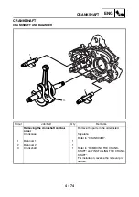
INSTALLING THE CRANKSHAFT
1. Install:
• crankshaft
1
NOTE:
_
Hold the connecting rod at the Top Dead Cen-
ter (TDC) with one hand while turning the nut
of the installing tool with the other. Operate the
installing tool until the crankshaft bottoms
against the bearing.
CAUTION:
_
Apply engine oil to each bearing to protect
the crankshaft against scratches and to
make installation easier.
Crankshaft installer pot
2
90890-01274
Installer pot
YU-90058
Pot installer
YU-90059
Crankshaft installer bolt
3
90890-01275
Bolt
YU-90060
Adapter (M16)
4
90890-04130
Adapter #13
YM-04059
Spacer (crankshaft installer)
5
90890-04081
Pot spacer
YM-91044
1
5
4
3
2
Summary of Contents for YFM700RV 2006
Page 1: ...YFM700RV SERVICE MANUAL 1S3 28197 E0 ...
Page 34: ...2 11 SPEC ENGINE SPECIFICATIONS Cylinder head tightening sequence 1 3 2 4 5 7 8 6 ...
Page 52: ...2 29 SPEC OIL FLOW DIAGRAMS 1 Oil delivery pipe 2 Oil filter 3 Oil pump 2 3 A A A A 2 1 ...
Page 55: ...2 32 SPEC OIL FLOW DIAGRAMS 1 Balancer 1 2 Crankshaft 2 1 ...
Page 408: ...YAMAHA MOTOR CO LTD 2500 SHINGAI IWATA SHIZUOKA JAPAN ...

