


ENG
CLUTCH
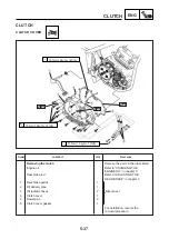
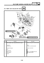
PULL LEVER SHAFT
Removing the pull lever shaft
Remove the parts in the order listed
Clutch pedal
Refer to “REMOVING THE ENGINE”
Starter worm gear
Refer to “STARTER MOTOR”
Neutral switch wire
Engine left cover
1
Clutch cable
1
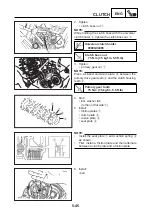
2
Bolt
1
3
Push lever shaft
1
4
Spring
1
Disconnect
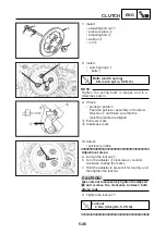
5
Locknut
1
6
Bearing
1
7
Spacer
1
For installation, reverse the
removal procedure
Job/Part
Qt’y
Remarks
Order
5-38
3
4
5
6
7
2
1
12 N.m (1.2 kgf.m, 8.85 ft.lb)
New
New
Summary of Contents for YBR250 2007
Page 1: ...YBR250 SERVICE MANUAL 5D1 F8197 E0 2007 ...
Page 2: ......
Page 359: ...YAMAHA MOTOR DA AMAZÔNIA LTDA ...


