CHASSIS
3-20
EAS21140
CHASSIS
EAS21190
ADJUSTING THE REAR DISC BRAKE
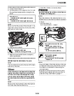
1. Check:
• Brake pedal position
(distance “a” from the top of the rider footrest
to the top of the brake pedal)
Out of specification
→
Adjust.
2. Adjust:
• Brake pedal position
▼▼▼
▼
▼
▼▼▼
▼
▼
▼▼▼
▼
▼
▼▼▼
▼
▼
▼▼▼
▼
▼
▼▼▼
▼
▼▼▼
a. Loosen the locknut “1”.
b. Turn the adjusting bolt “2” in direction “a” or
“b” until the specified brake pedal position is
obtained.
WARNING
EWA13070
After adjusting the brake pedal position,
check that the end of the adjusting bolt “c” is
visible through the hole “d”.
c. Tighten the locknut.
WARNING
EW1D71005
A soft or spongy feeling in the brake pedal
can indicate the presence of air in the brake
system. Before the vehicle is operated, the
air must be removed by bleeding the brake
system. Air in the brake system will consid-
erably reduce braking performance.
CAUTION:
ECA13510
After adjusting the brake pedal position,
make sure there is no brake drag.
▲▲▲
▲
▲
▲▲▲
▲
▲
▲▲▲
▲
▲
▲▲▲
▲
▲
▲▲▲
▲
▲
▲▲▲
▲
▲▲▲
3. Adjust:
• Rear brake light switch
Refer to “ADJUSTING THE REAR BRAKE
LIGHT SWITCH” on page 3-22.
EAS21240
CHECKING THE BRAKE FLUID LEVEL
1. Stand the vehicle on a level surface.
NOTE:
• Place the vehicle on a suitable stand.
• Make sure the vehicle is upright.
2. Remove:
• Rider seat
Refer to “GENERAL CHASSIS” on page 4-1.
3. Check:
• Brake fluid level
Below the minimum level mark “a”
→
Add the
recommended brake fluid to the proper level.
Brake pedal position
110.0 mm (4.33 in)
Direction “a”
Brake pedal is raised.
Direction “b”
Brake pedal is lowered.
a
1
2
a
b
Front brake
Recommended fluid
DOT 4
Rear brake
Recommended fluid
DOT 4
2
1
c
d
Summary of Contents for XV19SW 2006
Page 6: ......
Page 8: ......
Page 24: ...SPECIAL TOOLS 1 15...
Page 55: ...LUBRICATION POINTS AND LUBRICANT TYPES 2 30...
Page 60: ...LUBRICATION SYSTEM CHART AND DIAGRAMS 2 35 D D B B D D C C A A B C C B 3 2 1 3 4 6 7 6 7 5...
Page 62: ...LUBRICATION SYSTEM CHART AND DIAGRAMS 2 37 A A A A 1 3 2 4...
Page 64: ...LUBRICATION SYSTEM CHART AND DIAGRAMS 2 39 A 1 2 3 4...
Page 66: ...LUBRICATION SYSTEM CHART AND DIAGRAMS 2 41 A A A 1 5 5 1 3 2 4 B B B B...
Page 68: ...LUBRICATION SYSTEM CHART AND DIAGRAMS 2 43 1 2...
Page 69: ...LUBRICATION SYSTEM CHART AND DIAGRAMS 2 44 1 Transfer gear oil pump 2 Middle driven shaft...
Page 78: ...CABLE ROUTING 2 53...
Page 86: ...CABLE ROUTING 2 61...
Page 89: ......
Page 122: ...ELECTRICAL SYSTEM 3 33 a b 1...
Page 125: ......

