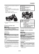
3-28
CHASSIS
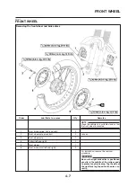
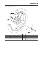
CHECKING THE WHEELS
The following procedure applies to both of the
wheels.
1. Check:
• Wheel rim
Damage/out-of-round
→
Replace.
EWA13260
WARNING
Never attempt to make any repairs to the
rim.
NOTE:
After a tire or rim has been changed or re-
placed, always balance the wheel.
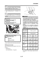
SPOKE INSPECTION AND TIGHTENING
1. Check:
• Spokes “1”
Curvature/Damaged
→
Replace.
Loose spoke
→
Tighten.
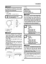
2. Tighten:
• Spoke (s)
NOTE:
Tighten the spokes before and after the break-
in period.
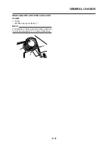
EAS00170
CHECKING AND LUBRICATING THE
CABLES
The following procedure applies to all of the in-
ner and outer cables.
WARNING
Damaged outer cable may cause the cable
to corrode and interfere with its movement.
Replace damaged outer cable and inner
cables as soon as possible.
1. Check:
• Outer cable
Damage
→
Replace.
2. Check:
• Cable operation
Rough movement
→
Lubricate.
NOTE:
Hold the cable end upright and pour a few
drops of lubricant into the cable sheath or use
a suitable lubricating device.
EAS00171
LUBRICATING THE LEVERS AND
BRAKE PEDAL
Lubricate the pivoting point and metal-to-metal
moving parts of the levers and brake pedal.
EAS00172
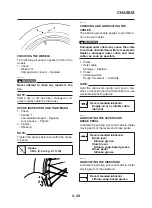
LUBRICATING THE SIDESTAND
Lubricate the pivoting point and metal-to-metal
moving parts of the sidestand.
Recommended lubricant
Lithium-soap-based grease
Recommended lubricant
Engine oil or a suitable cable
lubricant
Recommended lubricants
Brake lever
Silicone grease
Clutch lever
Lithium-soap-based grease
Brake pedal
Silicone grease
Spoke
3 Nm (0.3 m·kg, 2.1 ft·lb)
Summary of Contents for XT660Z 2008
Page 1: ...SERVICE MANUAL 2008 11D F8197 E0 XT660Z ...
Page 8: ......
Page 24: ......
Page 44: ...2 20 TIGHTENING TORQUES Cylinder head tightening sequence 2 4 3 1 ...
Page 54: ...2 30 COOLING SYSTEM DIAGRAMS 1 2 3 4 5 6 7 9 10 11 12 5 8 11 A ...
Page 57: ...2 33 LUBRICATION DIAGRAMS LUBRICATION DIAGRAMS 1 A A A A B B B A A B 3 2 2 4 1 1 5 5 ...
Page 59: ...2 35 LUBRICATION DIAGRAMS A A A A 3 1 2 3 4 ...
Page 60: ...2 36 LUBRICATION DIAGRAMS 1 Oil delivery pipe 2 2 Oil delivery pipe 1 3 Oil filter 4 Oil pump ...
Page 61: ...2 37 LUBRICATION DIAGRAMS 1 7 2 3 4 5 6 A ...
Page 63: ...2 39 LUBRICATION DIAGRAMS 1 6 5 4 3 2 ...
Page 65: ...2 41 CABLE ROUTING CABLE ROUTING ...
Page 67: ...2 43 CABLE ROUTING ...
Page 69: ...2 45 CABLE ROUTING ...
Page 71: ...2 47 CABLE ROUTING ...
Page 73: ...2 49 CABLE ROUTING ...
Page 75: ...2 51 CABLE ROUTING ...
Page 77: ...2 53 CABLE ROUTING ...
Page 79: ...2 55 CABLE ROUTING ...
Page 81: ...2 57 CABLE ROUTING ...
Page 83: ...2 59 CABLE ROUTING ...
Page 176: ...4 56 FRONT FORK WARNING Make sure the brake hoses are routed prop erly 1 2 3 ...
Page 270: ......
Page 284: ......
Page 301: ...7 17 FUEL INJECTION SYSTEM WIRING DIAGRAM ...
Page 324: ......
Page 327: ...8 1 IGNITION SYSTEM EAS27090 IGNITION SYSTEM EAS27110 CIRCUIT DIAGRAM ...
Page 331: ...8 5 ELECTRIC STARTING SYSTEM EAS27160 ELECTRIC STARTING SYSTEM EAS27170 CIRCUIT DIAGRAM ...
Page 337: ...8 11 CHARGING SYSTEM EAS27200 CHARGING SYSTEM EAS27210 CIRCUIT DIAGRAM ...
Page 338: ...8 12 CHARGING SYSTEM 2 A C magneto 5 Rectifier regulator 7 Battery 8 Main fuse ...
Page 340: ...8 14 CHARGING SYSTEM ...
Page 341: ...8 15 LIGHTING SYSTEM EAS27240 LIGHTING SYSTEM EAS27250 CIRCUIT DIAGRAM ...
Page 345: ...8 19 SIGNALING SYSTEM EAS27270 SIGNALING SYSTEM EAS27280 CIRCUIT DIAGRAM ...
Page 351: ...8 25 COOLING SYSTEM EAS00807 COOLING SYSTEM CIRCUIT DIAGRAM ...
Page 354: ...8 28 COOLING SYSTEM ...
Page 355: ...8 29 IMMOBILIZER SYSTEM ET5YU1002 IMMOBILIZER SYSTEM ET5YU1003 CIRCUIT DIAGRAM ...
Page 364: ...8 38 IMMOBILIZER SYSTEM ...
Page 365: ...8 39 ELECTRICAL COMPONENTS EAS27970 ELECTRICAL COMPONENTS ...
Page 367: ...8 41 ELECTRICAL COMPONENTS ...
Page 369: ...8 43 ELECTRICAL COMPONENTS EAS27980 CHECKING THE SWITCHES ...
Page 388: ......
Page 390: ......
Page 396: ...COLOR CODE ...
Page 397: ......
Page 398: ...YAMAHA MOTOR ITALIA S P A ...
Page 399: ...XT660Z 2008 WIRING DIAGRAM ...

