


FEATURES
1-11
Traction control system
The traction control system (TCS) helps maintain traction when accelerating on slippery surfaces, such
as unpaved or wet roads. If sensors detect that the rear wheel is starting to slip (uncontrolled spinning),
the traction control system assists by regulating engine power as needed until traction is restored.
When traction control has engaged, the “ ” indicator light will flash. You may notice changes in engine
response or exhaust sounds.
WARNING
EWA18860
The traction control system is not a substitute for riding appropriately for the conditions. Trac-
tion control cannot prevent loss of traction due to excessive speed when entering turns, when
accelerating hard at a sharp lean angle, or while braking, and cannot prevent front wheel slip-
ping. As with any vehicle, approach surfaces that may be slippery with caution and avoid espe-
cially slippery surfaces.
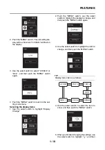
Setting the traction control system
When the vehicle is turned on, traction control is automatically turned on.
To turn the traction control system off, refer to “Setting mode” on page 1-16.
TIP
Turn the traction control system off to help free the rear wheel if the vehicle gets stuck in mud, sand, or
other soft surfaces.
NOTICE
ECA19650
Use only the specified tires. Using different sized tires will prevent the traction control system
from controlling tire rotation accurately.
Resetting the traction control system
The traction control system will automatically disable under certain conditions; such as when a sensor
fault is detected, or when only one wheel is allowed to rotate for more than a few seconds. Should this
happen, the “ ” indicator light will come on, and possibly the “
” warning light, too.
TIP
When the vehicle is on the centerstand, do not rev the engine for an extended period of time. Otherwise,
the traction control system will automatically disable and need to be reset.
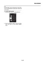
If the traction control system automatically disables, try resetting it as follows.
1. Stop the vehicle and turn it off completely.
2. Wait a few seconds and then turn the vehicle power on.
3. The “ ” indicator light should turn off and the system be enabled.
TIP
If the “ ” indicator light remains on after resetting, check the fuel injection system (Refer to “FUEL IN-
JECTION SYSTEM” on page 8-55).
4. Check the vehicle and turn off the “
” warning light.
1
1. Traction control system indicator light “ ”
Summary of Contents for TMAX XP530E-A 2017
Page 1: ...2017 SERVICE MANUAL XP530E A XP530 A XP530D A BV1 28197 E0...
Page 2: ......
Page 8: ......
Page 46: ...SPECIAL TOOLS 1 37...
Page 66: ...LUBRICATION SYSTEM CHART AND DIAGRAMS 2 19 EAS30021 LUBRICATION DIAGRAMS...
Page 68: ...LUBRICATION SYSTEM CHART AND DIAGRAMS 2 21...
Page 70: ...LUBRICATION SYSTEM CHART AND DIAGRAMS 2 23...
Page 71: ...LUBRICATION SYSTEM CHART AND DIAGRAMS 2 24 1 Oil strainer 2 Intake camshaft 3 Exhaust camshaft...
Page 72: ...LUBRICATION SYSTEM CHART AND DIAGRAMS 2 25...
Page 74: ...COOLING SYSTEM DIAGRAMS 2 27 EAS20020 COOLING SYSTEM DIAGRAMS...
Page 76: ...COOLING SYSTEM DIAGRAMS 2 29...
Page 78: ...CABLE ROUTING 2 31 EAS20021 CABLE ROUTING Headlight stay front view...
Page 80: ...CABLE ROUTING 2 33 Front cowling assembly rear view...
Page 82: ...CABLE ROUTING 2 35 Frame right side view...
Page 84: ...CABLE ROUTING 2 37 Frame right side view...
Page 86: ...CABLE ROUTING 2 39 Frame left side view...
Page 88: ...CABLE ROUTING 2 41 Rear frame left side view...
Page 90: ...CABLE ROUTING 2 43 Frame left side view...
Page 92: ...CABLE ROUTING 2 45 Frame top view...
Page 94: ...CABLE ROUTING 2 47 Frame top view...
Page 96: ...CABLE ROUTING 2 49 Handlebar top and left side view for XP530E A XP530 A...
Page 98: ...CABLE ROUTING 2 51 Handlebar front view for XP530E A XP530 A...
Page 100: ...CABLE ROUTING 2 53 Handlebar top and left side view for XP530D A...
Page 102: ...CABLE ROUTING 2 55 Handlebar front view for XP530D A...
Page 104: ...CABLE ROUTING 2 57 Front brake front left side and right side view...
Page 106: ...CABLE ROUTING 2 59 Frame right side view...
Page 108: ...CABLE ROUTING 2 61 Rear brake right side view...
Page 110: ...CABLE ROUTING 2 63 Fuel tank right side view...
Page 112: ...CABLE ROUTING 2 65 Fuel tank left side view...
Page 114: ...CABLE ROUTING 2 67 Fuel tank top view...
Page 116: ...CABLE ROUTING 2 69 Air filter case and throttle body left side view...
Page 118: ...CABLE ROUTING 2 71 Radiator right side view...
Page 120: ...CABLE ROUTING 2 73 Radiator left side view...
Page 122: ...CABLE ROUTING 2 75 Radiator top view...
Page 124: ...CABLE ROUTING 2 77 Hydraulic unit assembly top and front view...
Page 126: ...CABLE ROUTING 2 79...
Page 164: ...PERIODIC MAINTENANCE 3 36...
Page 355: ...CRANKSHAFT 5 76 2 1 2 4 3...
Page 358: ...TRANSMISSION 5 79...
Page 363: ...RADIATOR 6 4 pressure c Measure the indicated pressure with the gauge...
Page 387: ...THROTTLE BODY 7 14 2 2...
Page 388: ...THROTTLE BODY 7 15...
Page 392: ...IGNITION SYSTEM 8 1 EAS20072 IGNITION SYSTEM EAS30490 CIRCUIT DIAGRAM XP530E A...
Page 394: ...IGNITION SYSTEM 8 3 XP530 A...
Page 396: ...IGNITION SYSTEM 8 5 XP530D A...
Page 402: ...ELECTRIC STARTING SYSTEM 8 11 XP530 A...
Page 404: ...ELECTRIC STARTING SYSTEM 8 13 XP530D A...
Page 410: ...CHARGING SYSTEM 8 19 EAS20074 CHARGING SYSTEM EAS30496 CIRCUIT DIAGRAM XP530E A...
Page 412: ...CHARGING SYSTEM 8 21 XP530 A...
Page 414: ...CHARGING SYSTEM 8 23 XP530D A...
Page 417: ...CHARGING SYSTEM 8 26...
Page 418: ...LIGHTING SYSTEM 8 27 EAS20075 LIGHTING SYSTEM EAS30498 CIRCUIT DIAGRAM XP530E A...
Page 420: ...LIGHTING SYSTEM 8 29 XP530 A...
Page 422: ...LIGHTING SYSTEM 8 31 XP530D A...
Page 426: ...SIGNALING SYSTEM 8 35 EAS20076 SIGNALING SYSTEM EAS30500 CIRCUIT DIAGRAM XP530E A...
Page 428: ...SIGNALING SYSTEM 8 37 XP530 A...
Page 430: ...SIGNALING SYSTEM 8 39 XP530D A...
Page 437: ...SIGNALING SYSTEM 8 46...
Page 438: ...COOLING SYSTEM 8 47 EAS20077 COOLING SYSTEM EAS30502 CIRCUIT DIAGRAM XP530E A...
Page 440: ...COOLING SYSTEM 8 49 XP530 A...
Page 442: ...COOLING SYSTEM 8 51 XP530D A...
Page 445: ...COOLING SYSTEM 8 54...
Page 446: ...FUEL INJECTION SYSTEM 8 55 EAS20078 FUEL INJECTION SYSTEM EAS30504 CIRCUIT DIAGRAM XP530E A...
Page 448: ...FUEL INJECTION SYSTEM 8 57 XP530 A...
Page 450: ...FUEL INJECTION SYSTEM 8 59 XP530D A...
Page 507: ...FUEL INJECTION SYSTEM 8 116...
Page 525: ...CRUISE CONTROL SYSTEM for XP530D A 8 134...
Page 526: ...FUEL PUMP SYSTEM 8 135 EAS20081 FUEL PUMP SYSTEM EAS30513 CIRCUIT DIAGRAM XP530E A...
Page 528: ...FUEL PUMP SYSTEM 8 137 XP530 A...
Page 530: ...FUEL PUMP SYSTEM 8 139 XP530D A...
Page 533: ...FUEL PUMP SYSTEM 8 142...
Page 547: ...SEAT HEATER SYSTEM for XP530D A 8 156...
Page 550: ...ABS Anti lock Brake System 8 159 XP530 A...
Page 552: ...ABS Anti lock Brake System 8 161 XP530D A...
Page 554: ...ABS Anti lock Brake System 8 163 EAS30525 ABS COMPONENTS CHART 5 6 7 2 8 10 9 1 4 4 3...
Page 583: ...ABS Anti lock Brake System 8 192...
Page 584: ...SMART KEY SYSTEM 8 193 EAS20201 SMART KEY SYSTEM EAS31452 CIRCUIT DIAGRAM XP530E A...
Page 586: ...SMART KEY SYSTEM 8 195 XP530 A...
Page 588: ...SMART KEY SYSTEM 8 197 XP530D A...
Page 605: ...SMART KEY SYSTEM 8 214...
Page 608: ...ELECTRICAL COMPONENTS 8 217 1 2 3 4 5 6 7 8 9 10 11 13 12...
Page 610: ...ELECTRICAL COMPONENTS 8 219 22 3 4 6 5 7 8 9 10 11 12 13 14 15 16 17 20 21 19 2 18 1...
Page 664: ...EVENT CODE TABLE 9 21...
Page 669: ......
Page 670: ......