background image

5: EFFECT TYPE

The SY85 features a complex, high-performance effect system that can be pro-

grammed easily via the parameters presented here and in the following screen.

For a complete list of effect parameters see page 274.

Effect Type 1/2

Range: 0 ... 90
Controls: [CS1]/[CS4], [-1] [+1], Dial

[CS1] selects any of the SY85’s 90 effect types for the EFFECT 1 proces-

sor, and [CS4] does the same for the EFFECT 2 processor. See page 254 for
more details on the SY85 effect system.

Wet Balance 1/2

Range: 0 ... 100

Controls: [CS7]/[CS8], [-1] [+1], Dial

[CS7] controls the balance between the direct no-effect sound and the effect

sound of the EFFECT 1 processor, while [CS8] does the same for the EFFECT
2 processor. The higher the value the deeper the effect. See page 254 for more
details on the SY85 effect system.

PERFORMANCE EDIT MODE / 

QUICK EDIT 

35

Summary of Contents for SY85

Page 1: ...YAMAHA YAMAHA AUTHORIZED PRODUCT MANUAL MUSIC SYNTHESIZER ...

Page 2: ...YAMAHA MUSIC SYNTHESIZER ...

Page 3: ...rence MAIN FEATURES l l AWM2 Tone Generator System 2nd generation Advanced Wave Memory AWM2 technology delivers dazzling true to life sound with 30 note polyphony l l Large capacity Waveform ROM A large 6 megabytc waveform ROM provides plenty of capacity for top quality samples l l Expandable Waveform RAM The SY85 comes supplied with 512 kilobytes of waveform RAM that can be used to load extra wav...

Page 4: ...on matrix further enhances operation by allowing fast easy access to any of the SY85 modes l l 9 track 10 song Sequencer Full function sequencer with 8 standard tracks and 1 dedicated rhythm track Each sequencer song has its own 16 part multi instrument setup Rhythm parts can be recorded as patterns and then chained to form the com plete rhythm track The SY85 also includes 100 rhythm patterns that...

Page 5: ...ncer Demo 18 n Load the Pre programmed Voice Performance Pattern Data 20 2 Selecting And Playing Voices n Play the Internal Voices 21 n CARD Voice Memory 26 n Real time Control 27 PITCH BEND WHEEL 27 MODULATION WHEEL 27 CONTINUOUS SLIDERS 28 FOOT CONTROLLER 29 KEYBOARD AFTERTOUCH 29 3 The Performance Mode n Play the Internal Performance Combinations 30 n CARD Performance Memory 32 n Programming Yo...

Page 6: ...AL PATTERN REAL TIME 56 RECORDING AN ORIGINAL PATTERN STEP RECORD 58 BUILDING A RHYTHM TRACK 60 F5 INS Rhythm Track Insert 62 F6 DEL Rhythm Track Delete 62 F7 CPY Rhythm Track Copy 63 F8 SCH Rhythm Track Search 63 6 Data Management n Cards or Disks 64 MCD64 RAM Cards 64 Floppy Disks 64 n Create a Well organized Data Library 65 n Make Separate Performance Disks or Cards 65 n MIDI Data Recorder Capa...

Page 7: ...multi plug adapters since these can result in reduced sound quality and possibly damage n Turn Power OFF When Making Connections To avoid damage to the instrument and other devices to which it is con nected a sound system for example turn the power switches of all related devices OFF prior to connecting or disconnecting audio and MIDI cables n n MIDI Connections When connecting the SY85 to MIDI eq...

Page 8: ...n the disk so it is advisable to make a second back up copy of disks that contain very important data and keep backup disks in a safe place away from stray magnetic fields i e away from speakers appliances containing motors etc n Handle Floppy Disks and the Disk Drive With Care Use only 3 5 2DD type floppy disks Do not bend or apply pressure to the floppy disk Do not open the shutter and touch the...

Page 9: ...vice and Modification The SY85 contains no user serviceable parts Opening it or tampering with it in anyway can lead to irreparable damage and possibly electric shock Refer all servicing to qualified YAMAHA personnel n Third party Software Yamaha can not take any responsibility for software produced for this prod uct by third party manufacturers Please direct any questions or comments about such s...

Page 10: ...L 1 INTERNAL 2 and CARD memories and using the real time controls 3 The Performance Mode Page 30 Selecting and playing performance combinations from the INTERNAL 1 INTERNAL 2 and CARD memories and programming original perform ance combinations 4 Voice Editing Effects Page 40 Fast easy voice editing and effect setup using the VOICE QUICK EDIT mode 5 The Sequencer Page 47 Recording and playing seque...

Page 11: ...age software mal function or any other serious problem that may occur due to improper operation or set up This icon marks information that you must read i e im portant steps or procedures that are essential for proper efficient or easy operation The magnifying glass icon indicates information that may not be essential for general operation but is a more detailed explanation of a feature a descript...

Page 12: ...tern Edit Mode Page 201 6 Utility Mode Page 209 7 Wave Edit Mode Page 237 Once you have become familiar with the way the SY85 works by going through the Getting Started manual you should only need to refer to the Fea ture Reference manual from time to time to get details on functions you ve never used before or refresh your memory about functions that you don t use very often Each section of the F...

Page 13: ... the various SY85 modes while the SUB MODE keys select the various sub modes related to each main mode This system provides direct easy access to any mode without the need for a com plex multi level control interface PITCH BEND Wheel This self centering pitch wheel allows smooth upward and downward pitch bends 10 ...

Page 14: ...mplitude modulation frequency modulation envelope generator bias and filter cutoff frequency control for a range of expressive effects Keyboard The SY85 has a 61 key keyboard that is both velocity and after touch sensitive for broad intimate expressive control 11 ...

Page 15: ... key for editing CS1 through CS8 Continuous Sliders In the voice and performance play modes these controls are used for real time expressive control In the edit and utility modes however they are used to edit the parameters that appear immediately above each continuous slider on the display SHIFT Key The SHIFT key is sometimes used to access secondary functions param eters or displays It is also u...

Page 16: ...ce numbers when for example you re looking for a voice but don t know the voice number It s also handy for making large value changes in any of the edit modes PAGE and MENU Keys In any of the edit and utility modes these keys are used to select the vari ous edit screens The and are used to scroll backward or forward through the available screens one at a time while the MENU key calls a menu that a...

Page 17: ... high volume storage of voice performance sequencer and wave data The disk in use indicator below the drive slot lights while any disk operation is in progress NEVER attempt to remove a disk or turn the power off while a disk operation is in progress The eject button also below the disk slot is used to remove disks from the drive DATA WAVEFORM Card Slots The DATA slot accepts Yamaha MCD64 Memory C...

Page 18: ...stereo outputs from the SY85 If plugs are only inserted into the OUTPUT 1 1 2 jacks then the OUTPUT 2 signals are combined with the OUTPUT 1 signals and delivered via the OUTPUT 1 1 2 jacks Further if a plug is inserted only into the L MONO jack the left and right channel signals are combined and delivered via this jack for connection to a monaural sound system SUSTAIN Jack An optional Yamaha FC4 ...

Page 19: ...the sequencer MIDI IN OUT and THRU Connectors The MIDI IN connector receives the data from an external sequencer or other MIDI device which is to control or transmit data to the SY85 The MIDI THRU connector simply re transmits the data received at the MIDI IN connec tor allowing convenient chaining of MIDI devices The MIDI OUT connector transmits data corresponding to all SY85 performance operatio...

Page 20: ... diagram below shows the basic connections in a setup using only the SY85 and a stereo sound system Make sure that both the SY85 and your sound system are turned OFF when making connections 1 Setting Up Your System 17 ...

Page 21: ... connected to the SY85 MIDI OUT connector If the SY85 is connected to other MIDI equipment the SY85 power switch should be turned ON first and turned OFF last Load Play the Sequencer Demo Once you ve set up your SY85 system you might like to load and play the demo sequence provided on the DEMO disk Loading the demo data overwrites the sequencer wave and voice memory so if you have any important da...

Page 22: ...NTER YES a second time to actually begin loading the data BUSY Now executing will appear on the display while the data is being loaded 4 Engage the SONG Mode When the data has finished loading press the SONG key to engage the song mode 5 Play the Demo Press the SEQUENCER RUN key to play the demo sequence You can stop playback at any time by pressing the STOP key 6 Eject the Disk Press the eject bu...

Page 23: ...rst and the label side of the disk should face upward 2 Select the Utility DISK ALL LOAD Function Press the UTILITY button so that its indicator lights then press the SUB MODE DISK key the lowest SUB MODE key A display with the word DISK in the upper left corner should appear If necessary press the PAGE key a few times until the DISK ALL display shown above appears Also press the Fl key to make su...

Page 24: ...key so that its indicator lights and the words VOICE PLAY appear on the top line of the LCD panel The information displayed on the bottom display line tells you about the current effect mode and what effects are assigned to the SY85 s two effect processors See the Effects section beginning on page 254 of the Feature Reference manual for more details 2 Select an Internal Voice Memory Bank Each INTE...

Page 25: ...UP keys A through H and its number using the PROGRAM keys 1 through 8 To select voice D7 for example first press the GROUP D key and then the PROGRAM 7 key The GROUP D key indicator will flash until the PROGRAM 7 key is pressed and the D7 voice is actually engaged To select a different voice within the same group it is only necessary to press the appropriate PROGRAM key To select a different group...

Page 26: ...oice number boundary The Data Entry Wheel provides a fast efficient way to cover a broad range of voice numbers when for example you re looking for a voice but don t know the voice number As usual use the MEMORY keys to select the memory group then rotate the data entry wheel while watch ing the display The groups are automatically switched as the voice numbers are changed 4 Play Try playing the s...

Page 27: ...Internal Voice List INTERNAL VOICE 1 INTERNAL VOICE 2 24 2 Selecting And Playing Voices ...

Page 28: ...2 Selecting And Playing Voices 25 ...

Page 29: ...asonable level make sure that the SY85 OUTPUT 1 and OUTPUT 2 controls are turned up to a reasonable level and check all connections carefully n CARD Voice Memory The CARD memory is an optional Yamaha MCD64 Memory Card or pre programmed voice card plugged into the SY85 DATA slot Memory cards are convenient for external storage and transportation of voices you or others create You can also store set...

Page 30: ...e manual will apply only to the current voice PITCH BEND WHEEL Rolling the PITCH wheel upward away from you will raise the pitch of notes played on the keyboard while rolling the wheel in the opposite direction will lower the pitch The PITCH wheel is self centering and will always return to center position normal pitch when released The maximum range of the PITCH wheel can be set using the PITCH f...

Page 31: ...ils about the effect system CS3 CS4 are assignable to just about any voice parameters Although initial assignments are factory programmed for the voices provided with the SY85 they can be changed to suit your specific musical requirements by using the VOICE EDIT mode CS3 PARAMETER EDIT and CS4 PARAMETER EDIT functions descibed on pages 89 and 91 of the Feature Reference manual CS5 AR controls the ...

Page 32: ...most frequently used for vibrato control the harder you press the keys the more vibrato is applied This makes it possi ble to control vibrato without having to remove one hand from the keyboard to use the MODULATION wheel For the same reason aftertouch is also often used for pitch control Many of the internal voices provided with the SY85 have preset aftertouch functions see the voice list on page...

Page 33: ...s indicator lights and the words PERFORMANCE PLAY appear on the top line of the LCD panel The information displayed on the bottom display line tells you about the current effect mode and what effects are assigned to the SY85 s two effect processors See the Effects section beginning on page 254 of the Feature Reference manual for more details 2 Select an Internal Performance Memory In the PERFORMAN...

Page 34: ...ce on the left hand side of the keyboard and another on the right Select a number of different performance combinations and try them out Here s an abbreviated performance list for easy reference n Internal Performance List INTERNAL PERFORMANCE 1 INTERNAL PERFORMANCE 2 In addition to the voice categories described on page 26 the performance mode has a CO combination category 3 The Performance Mode ...

Page 35: ...sing the CARD key Individual performance combinations are then selected by using the GROUP and PROGRAM keys or the 1 1 keys or data dial in exactly the same way as the INTERNAL voices and performance combinations A properly formatted Yamaha MCD64 memory card or an appropriate pre programmed voice card must be inserted in the CARD slot before the CARD memory can be selected If no memory card is pre...

Page 36: ... as volume effects and the performance name can also be programmed Layers can be played simultaneously across the entire keyboard limited to specific ranges to create split keyboard setups or overlapped in any way re quired It s also possible to use velocity switching to assign different velocity ranges to different layers so that for example one voice sounds when you play softly and a completely ...

Page 37: ...1 Select a Performance Combination Engage the PERFORMANCE mode and select any internal performance combination as described in the preceding section 2 Initialize the Selected Performance Combination Make sure that the PERFORMANCE key indicator is lit and then press the SUB MODE JOB key Press the PAGE a few times to select the PERFORMANCE JOB Initialize screen Press the F6 function key to ensure th...

Page 38: ...s the bottom of the display After initialization voice II A1 is assigned to all four layers Press the F2 function key to place the underline cursor under the layer A voice number note that the voice name is shown between parentheses in the upper right corner of the display then use the CS2 control slider or any of the voice selection methods already described to select voice number II C1 BA Wood N...

Page 39: ...just use CS6 to lower the volume of the layer C strings voice to 98 Notice that since layer D is turned off no parameter appears for the layer D voice In addition to using the control sliders these and most other parameters can be adjusted by first pressing the function key immediately below the parameter in order to select that parameter the underline cursor will appear below the selected paramet...

Page 40: ...que set the layer C lower note limit to C3 Although the current layer A lower limit C 2 as well as the layer B and layer C upper limits G8 extend beyond the key board these settings won t adversely affect our performance combination so we won t bother to change them 9 Play Try playing our new performance combination on the keyboard You should hear only the BA Wood voice when playing on the lower t...

Page 41: ...proce dure e g MEMORY GROUP and PROGRAM keys Press ENTER YES Press ENTER YES again Completed will appear briefly when the data has been stored then the SY85 will return to the PERFORMANCE PLAY mode If you return to the PERFORMANCE PLAY mode before storing the edited performance combination either by pressing the EXIT NO key or the PERFORMANCE key an inverse letter E will appear to the right of the...

Page 42: ...your perform ance combination an original name before storing it Further Possibilities When you re ready to explore the many other possibilities the SY85 pro vides for performance programming read through the PERFORMANCE EDIT MODE section of the Feature Reference manual page 13 3 The Performance Mode 39 ...

Page 43: ...y using the VOICE QUICK EDIT mode 1 Select a Voice In the VOICE PLAY mode select the voice you want to edit using the normal voice selection procedure 2 Press QUICK EDIT Press the SUB MODE QUICK EDIT key to engage the voice quick edit mode 3 Select and Set the WAVE Parameters If it doesn t appear immediately when the QUICK EDIT mode is engaged use the PAGE and keys to locate the QED WAVE screen Th...

Page 44: ...can also be used to select the memory area from which the wave is to be selected A complete listing of the internal waves is given in the Fea ture Reference manual appendix page 310 4 Select and Set the Amplitude Envelope Generator Parameters Use the PAGE and keys to locate the QED AEG Type screen Rather than having to set numerous level and rate values via the full edit amplitude envelope generat...

Page 45: ...5 sets the attack rate for the selected envelope 63 produces the fastest attack while 0 produces the slowest attack CS6 sets the sustain level for the selected envelope and CS7 sets the release rate for the selected envelope CS8 determines how the output level of the voice changes in response to velocity changes e g keyboard dynamics Plus settings produce higher output level in response to higher ...

Page 46: ...brass 1 Synthesizer brass 2 Sweep frequency filter Slow attack filter Initialized LPF initialized HPF Initialized BPF Initialized BEF No filter CS6 sets the cutoff frequency of the selected filter 0 127 Lower cutoff values produce a lower cutoff frequency and higher values produce a higher cutoff frequency If the Thru filter type is selected no cutoff fre quency can be set and appears on the displ...

Page 47: ...78 are selected when this parameter is set to CS5 sets the speed of the LFO 0 99 0 is the slowest speed setting producing an LFO speed of approximately 0 Hertz The fastest setting of 99 produces an LFO speed of approximately 25 Hertz CS6 sets the maximum amount of amplitude tremolo pitch vibrato or filter cutoff wahwah modulation that can be applied to the current voice A 0 setting produces no mod...

Page 48: ... the keyboard of course you can play at any time while editing to hear how it s progressing The COMPARE function lets you compare the sound of the edited voice with that of the original voice To engage the COMPARE mode press the STORE key while holding the SHIFT key The VOICE key indicator will flash and you ll hear the original pre edit voice when you play on the keyboard Press the EXIT NO key to...

Page 49: ... at this point and proceed as described above If you select a different voice before storing however the edited data will be lost Also note that any previous data in the voice memory location you store to will be overwritten by the new data You can use the VOICE NAME function described on page 95 of the Feature Reference manual to give your voice an original name before storing it n Further Possib...

Page 50: ... using the sequencer realtime or step write Both of these methods are described below Real time Recording Tracks 1 8 Realtime recording allows you to directly record anything you play on the keyboard capturing the spontaneous timing keyboard dynamics and controller operations of the performance Using the realtime recording mode is in fact very much like using a conventional tape recorder Realtime ...

Page 51: ...Select screen shown below This screen lets you select the voices that are to be played via the various multi setup channels 48 Only eight voice numbers are shown on the display at one time Use the PAGE and keys while holding the SHIFT key to switch between multi instruments 1 8 and 9 16 The currenty selected group of voices is indicated on the upper display line After moving the cursor to the inst...

Page 52: ...ntain some recorded data glow green The inidcator of the track to be recorded selected by pressing the appropriate GROUP or PROGRAM key glows red When the desired record track is selected the corresponding instrument in the current multi play setup will sound when the keyboard is played Select a Record Mode Use CS1 to select the desired record mode The different record modes are OVER Real time Ove...

Page 53: ...play back until the punch in point is reached then the replace record mode will be activated until the punch out point is reached allowing you to record the new material If recorded material exists following the punch out point playback will con tinue until the end of the sequence Set the Record Tempo Use CS5 to set the tempo you want to record at shown in beats per minute on the display The tempo...

Page 54: ...rent track press the STOP key to stop recording Both the RUN and RECORD key indicators will go out and Executing will appear on the display briefly while recorded data is being processed After this the SY85 will return to the sequencer play mode 6 Check the Part just Recorded You can now listen to the part you ve just recorded by pressing the sequencer top key see illustration below to return to t...

Page 55: ...ithout having to actually play the part on the keyboard This is ideal for entering difficult parts from written music or for extremely complex or fast passages that would be impossible to play in real time 1 Select the Step Record Mode The sequencer record mode is entered in the same was as described in the REALTIME RECORDING section above Instead of choosing the repl or over record mode select st...

Page 56: ... The number of 32nd note segments corresponding to the selected note length will be emphasized on the display If you select 8th notes in 4 4 time for example the display will look something like this Dotted Notes Pressing the dot key PROGRAM key 1 adds half the value of the currently displayed note length If this results in a standard note length it is displayed as a dotted note Otherwise it is di...

Page 57: ...he F6 function key immediately below ERASE on the display The diamond note marker will disappear If the diamond marks a chord the entire chord will be erased Switching Voices Mid track You can switch to a different voice anywhere in a track by entering a program change command at the required point After moving the cursor to the point at which you want to change voices in the step record edit disp...

Page 58: ...he cursor is below the pattern number to select a pattern number 00 99 The name of the pattern appears to the right of the number The letter to the right of the pattern name indicates whether it is a verse V fill in F or chorus C pattern The number below Meas on the display indicates how many measures long the patterns is 1 4 CS5 can be used to adjust the tempo below Tempo on the display The numbe...

Page 59: ...ecessary use CS6 to select the pattern you want to clear then press ENTER YES Respond to this Are you sure display by pressing ENTER YES again if you want to go ahead and clear the pattern or press EXIT NO to cancel the operation 2 Set the Pattern Record Parameters Engage the Record Mode Press the sequencer RECORD key to engage the record standby mode The red RECORD indicator will light Select a R...

Page 60: ... at which you want to enter the pattern data The available quantize values are 1 4 1 6 1 8 1 12 1 16 1 24 and 1 32 Quantization can also be turned off if you want maximum note resolution Set the Velocity Value The velocity of the notes to be entered is set via the NORM PRO GRAM 4 ACC1 through ACC3 PROGRAM 5 through 7 and FIX PROGRAM 8 keys The actual velocity values of the accents ACC1 through ACC...

Page 61: ...tempo quantize value or velocity value as required 5 Press STOP To Stop Recording When you have finished playing the part for the current track press the STOP key to stop recording Both the RUN and RECORD key indicators will go out and the SY85 will return to the pattern play mode 6 Check the Pattern just Recorded You can now listen to the part you ve just recorded by pressing the sequencer RUN ke...

Page 62: ...ou press the FIX PROGRAM 8 key and the notes will be entered at the velocity with which they are played on the keyboard 4 Select the Desired Note Length Select the note length for the first note by pressing the corresponding GROUP key standard notes are displayed above the keys or by incrementing decrementing using the 1 and 1 keys Dotted notes triplets and ties are entered in the same was as they...

Page 63: ...and press the key on the keyboard correpsonding to the instrument to be erased 7 Press STOPI When the pattern is finished press STOP to return to the PATTERN play mode Now you can press RUN and hear how the pattern sounds BUILDING A RHYTHM TRACK A rhythm track is built up as a sequence or parts each part corresponding to a single pattern The part sequence is specified in the SONG EDIT mode When th...

Page 64: ...define the tempo change the number to the left of the slash 99 0 99 or atmp for a tempo sets the number of beats per minute by which the tempo will decrease or increase and the number to the right of the slash 0 99 sets the number of beats from the tmp mark over which the change will occur A setting of 20 8 for example would increase the tempo by 20 beats per minute over 8 beats 2 measures of 4 4 ...

Page 65: ...play Press ENTER YES again to confirm that you want to go ahead with the insert operation or press EXIT NO to cancel When the event has been inserted Completed will appear briefly on the display then the display will return to the main rhythm track edit mode F6 DEL Rhythm Track Delete This function is used to delete a part from an existing rhythm track Press F6 to engage the rhythm track delete fu...

Page 66: ... ahead with the copy operation which will overwite existing parts from the destination part number or press EXIT NO to cancel When the parts have been copied Completed will appear briefly on the display then the display will return to the main rhythm track edit mode F8 SCH Rhythm Track Search This function makes it possible to directly locate marks entered in the track using the mark event in the ...

Page 67: ...ct and convenient to carry Fast data transfer Reliable Disadvantages More expensive than disks Only stores synthesizer data this is not a problem for most performance applications Limited capacity Never attempt to force a voice card into the waveform slot or vice versa Doing so can cause serious damage to the card connectors Floppy Disks There s no substitute for floppy disks if you need to store ...

Page 68: ...be working in the studio or some other situation in which you don t know exactly what data you ll need it s probably a good idea to take your entire data library along Actually it s better to take a copy of your data library and leave the master disks at home so all your data can t be lost or destroyed at once If you will be performing on stage or in any situation involving predetermined sets and ...

Page 69: ...ata from other MIDI equipment to be retained in memory or saved to disk and then trans ferred back to the appropriate MIDI devices as required This means the SY85 can serve as a central data storage facility for your entire performance system Refer to the MDR section beginning on page 228 of the Feature reference manual for operational details 66 6 Data Management ...

Page 70: ... no key 13 F Filter parameters 42 Floppy disk drive 14 Floppy disks drive handling 5 Floppy disks advantages 64 Foot controller jack 16 17 29 Foot volume jack 16 Function keys 12 H Handling transport 4 I Icons 8 Initialize performance 34 Instrument display selection 60 Internal patterns selection 55 Internal performance combinations selection 30 Internal voices selection 21 K Keyboard 11 L LFO par...

Page 71: ... Quick edit envelope types 42 Quick edit filter types 43 Quick edit wave groups 41 68 INDEX R RAM cards 64 Real time control 27 Real time pattern record 56 Real time recording 47 Record mode 49 Record tempo 50 57 Record track 49 Repeats 61 Replace recording 49 Rests 54 Rhythm track 55 Rhythm track copy 63 Rhythm track delete 62 Rhythm track insert 62 Rhythm track search 63 Search mark 61 Sequencer...

Page 72: ...ories 26 Voice edit 40 Voice list 24 Voice play mode 21 Voice selection performance 35 Volume change 61 Volume settings performance 36 W Wave parameters 40 Wave RAM expansion slots 16 Waveform card slot 14 1 and 1 keys 13 23 INDEX 69 ...

Page 73: ...YAMAHA MUSIC SYNTHESIZER ...

Page 74: ... antenna If the antenna lead in is 300 ohm ribbon lead change the lead in to co axial type cable If these corrective measures do not produce satisfactory results please contact the local retailer authorized to distribute this type of product If you can not locate the appropriate retailer please contact Yamaha Corporation of America Electronic Service Division 6600 Orangethorpe Ave Buena Park CA 90...

Page 75: ...L ISSUES Yamaha strives to produce products that are both user safe and environmentally friendly We sincerely believe that our products and the production methods used to produce them meet these goals In keeping with both the letter and the spirit of the law we want you to be aware of the following Battery Notice This product MAY contain a small non rechargeable battery which if applicable is sold...

Page 76: ...n locations that do not significantly contribute to their operating temperature Placement of this product close to heat sources such as radiators heat registers and other devices that produce heat should be avoided 8 This product was NOT designed for use in wet damp locations and should not be used near water or exposed to rain Examples of wet damp locations are near a swim ming pool spa tub sink ...

Page 77: ...GENERAL EDITING PROCEDURE PERFORMANCE EDIT MODE VOICE EDIT MODE DRUM VOICE EDIT MODE SONG EDIT MODE PATTERN EDIT MODE UTILITY MODE WAVE EDIT MODE APPENDIX ...

Page 78: ...ffect Type 35 6 Effect Parameter 36 Effect Edit 1 Mode Type 2 Send Select Level 38 2 3 Layer Dry Output Select 40 4 Output Level 41 5 Wet Dry Balance 42 6 Send Effect 2 Mix Level 43 7 Effect 1 Parameters 44 8 Effect 2 Parameters 44 9 Control Parameters 45 10 Control LFO 47 Effect Data Copy 48 Effect Signal Flow Display 49 Job 1 Layer Controller Sync 50 2 Layer Exchange 51 3 Performance Edit Recall...

Page 79: ...ect Signal Flow Display 114 Job 1 Voice Edit Recall 115 2 Voice Initialize 116 Voice Compare 117 Voice Store 118 Drum Voice Edit Mode Edit 1 Key Parameters 1 120 2 Key Parameters 2 122 3 Total Level 123 4 Drum Voice Name 124 Drum Key Data Copy 125 Quick Edit 1 Effect Type 126 2 Effect Send Level 127 Effect Edit 1 Mode Type 128 2 Key Send Select Level 129 3 Key Dry Output Select 131 4 Output Level ...

Page 80: ... Track 181 182 4 Track Mixdown 183 5 Delete Track 185 6 Quantize 186 7 Copy Measure 188 8 Delete Measure 190 9 Insert Measure 191 10 Erase Measure 192 11 Remove Event 193 12 Clock Move 195 13 Transpose 196 14 Note Shift 197 4 15 Velocity Modify 198 16 Gate Time Modify 199 17 Crescendo 200 Pattern Edit Mode Job 1 Copy Pattern 202 2 Clear Pattern 203 3 Instrument Change 204 4 Velocity Modify 205 Pat...

Page 81: ...grams Voice Mode 256 Effect Signal Flow Diagrams Drum Voice Performance and Song Modes 264 The Effects Their Parameters 274 WAVE MEMORY EXPANSION 285 Memory Installation 286 INITIAL DATA BLANK CHART INITIAL PERFORMANCE InitPerf 289 INITIAL NORMAL VOICE InitVce 290 INITIAL DRUM VOICE DR PTN 292 INITIAL DRUM VOICE DR Zones 294 INITIAL DRUM VOICE DR GMIDI 296 INITIAL DRUM VOICE DR Efect 298 INITIAL M...

Page 82: ...GENERAL EDlTING PROCEDURE Mode Selection 8 Selecting Specific Edit Functions 8 Selecting Editing Parameters 10 Controller Assignment Display 11 ...

Page 83: ...so that its indica tor lights than press the second SUB MODE key in the VOICE column EDIT Selecting Specific Edit Functions Once you ve selected an edit mode one way to select the various edit screens and functions it contains is to use the PAGE and keys The and keys step backward and forward through the available screens respectively Hold either of these keys for continuous stepping in the specif...

Page 84: ...If you select 3 Filter after pressing the MENU key in the VOICE EDIT mode and then press ENTER YES you ll see the following display Hit ENTER will be flashing In this case press ENTER YES again to access the filter functions Once in the filter sub mode you can use the PAGE and or MENU keys to select the various filter functions as de scribed above When you have finished with the filter functions p...

Page 85: ...he CS5 slider can be used to adjust the Fine parameter The parameters can also be edited by first moving the cursor to the required parameter by pressing the corresponding function key F7 for example would select the Rndm parameter in the above display and then by using either the data entry dial or the 1 and 1 keys to adjust the parameter s value In some special cases you ll also use the function...

Page 86: ...ich sliders the SY85 features a controller assignment display that can be selected temporarily by pressing the SHIFT key in the VOICE or PERFORM ANCE PLAY mode PERFORMANCE PLAY mode VOICE PLAY mode DRUM VOICE PLAY mode This display shows the names of the parameters assigned to sliders CS1 through CS4 for the current voice or performance combination so you can take a quick peek to refresh your memo...

Page 87: ...31 33 35 36 Effect Edit 1 Mode Type 37 2 Send Select Level 38 3 Layer Dry Output Select 40 4 Output Level 41 5 Wet Dry Balance 42 6 Send Effect 2 Mix Level 43 7 Effect 1 Parameters 44 8 Effect 2 Parameters 44 9 Control Parameters 45 10 Control LFO 47 Effect Data Copy 48 Effect Signal Flow Display 49 Job 1 Layer Controller Sync 50 2 Layer Exchange 51 3 Performance Edit Recall 52 4 Performance Initi...

Page 88: ... then use the GROUP and PROGRAM keys to select the voice Voices within the selected memory bank can also be selected directy for each layer by the CS2 CS4 CS6 and CS8 keys Internal and card voices cannot be mixed The voices can individually turned on or off by using the off and on keys while holding the SHIFT key The name of the currently selected voice is shown in the upper right corner of the di...

Page 89: ...e voice is on a lower case letter if the voice is muted and a dash if the voice is off Volume Range 0 127 Controls CS2 CS4 CS6 CS8 1 1 Dial Use the CS2 CS4 CS6 and CS8 sliders to adjust the volume levels of the A B C and D layer voices respectively A setting of 0 produces no sound while a setting of 127 produces maximum volume The vertical bar graphs next to each parameter provide a visual indicat...

Page 90: ...lower case letter if the voice is muted and a dash if the voice is off Pan Range 31 31 Controls CS2 CS4 CS6 CS8 1 1 Dial Use the CS2 CS4 CS6 and CS8 sliders to adjust the pan positions of the A B C and D layer voices respectively Minus values represent pan ning to the left and positive values represent panning to the right 0 posi tions the sound of the selected layer in the center of the stereo so...

Page 91: ...g of 4 shifts the pitch up by a major third The Note Shift parameter can be used to transpose a voice to its most useful range or to create harmony intervals between different layers in a performance combination Voices that are turned off are indicated by on the display Fine Fine tuning Range 7 7 Controls CS2 CS4 CS6 CS8 1 1 Dial Allows slight upward or downward pitch adjustment of each active ele...

Page 92: ... CS3 CS5 and CS7 sliders to set the low note limits of the A B C and D layer voices respectively It is also possible to press the desired note on the keyboard while holding the SHIFT key The C 2 to G8 range of this parameter covers a full 10 1 2 octaves C3 corresponds to middle C on a keyboard This parameter in conjunction with the High Note Limit parameter de scribed below allows the sound from a...

Page 93: ...tive layer the highest note that each layer will produce Use the CS2 CS4 CS6 and CS8 sliders to set the high note limits of the A B C and D layer voices respectively It is also possible to press the desired note on the keyboard while holding the SHIFT key See the Lo parameter above for more details PERFORMANCE EDIT MODE 1 Layer 19 ...

Page 94: ...ocity limits of the A B C and D layer voices respectively It is also possible to play any note on the keyboard at the desired velocity while holding the SHIFT key Every note played on the keyboard or external MIDI controller produces a velocity value that tells the tone generator how hard the note has been played The range of MIDI velocity values is from 1 to 127 thus the 1 127 range of this param...

Page 95: ...es over which each active layer will produce output Use the CS2 CS4 CS6 and CS8 sliders to set the high velocity limits of the A B C and D layer voices respectively It is also possible to play any note on the keyboard at the desired velocity while holding the SHIFT key See the Lo parameter above for more details PERFORMANCE EDIT MODE 1 Layer 21 ...

Page 96: ...he voice is on a lower case letter if the voice is muted and a dash if the voice is off CS3 Enable Range on off Controls CS1 CS3 CS5 CS7 1 1 Dial The CS1 CS3 CS5 and CS7 sliders turn CS3 control of layers A B C and D on or off respectively Voices that are turned off and are not available for editing are indicated by on the display CS4 Enable Range on off Controls CS2 CS4 CS6 CS8 1 1 Dial The CS2 C...

Page 97: ...ea from which the source performance is to be selected Use the GROUP keys to select the source performance bank then use the PROGRAM keys to select the source performance number The CS5 slider and other data entry controls can also be used to select the source performance number Use the CS8 slider to select the source layer Once the source performance and layer has been selected press the EN TER Y...

Page 98: ...on when switching between performance combinations Total Level Range 0 127 Controls CS4 1 1 Dial Adjusts the volume of the current performance A setting of 0 produces no sound while a setting of 127 produces maximum volume A bar graph to the right of the parameter provides a visual indication of volume level the longer the bar the higher the volume 24 PERFORMANCE EDIT MODE 2 Volume ...

Page 99: ...lects the three characters printed above it in sequence It is also possible to use the 1 and 1 keys or dial to scroll through the available characters see list below The sliders CS1 through CS8 independently select characters for the corresponding character position CS1 selects the first character CS2 selects the second character and so on The first four function keys also perform important functi...

Page 100: ...cted screen Other voice edit screens can then be selected by using the and keys The available voice edit screens are listed below 1 Oscillator 2 Amplitude EG 3 Filter 4 Pitch EG 5 LFO 6 Controller 7 VOICE Total Level 8 VOICE Name While editing the voice parameters in voice edit screens 2 through 7 above the PROGRAM keys 1 through 4 LAYER SELECT A B C and D can be used to select a different layer f...

Page 101: ... produce a faster attack rate while minus values produce a slower attack rate No matter how much offset is applied the minimum and maximum EG attack rates cannot be exceeded R2 3 Decay 1 rate Range 63 63 Controls CS4 1 1 Dial Modifies the R2 and R3 parameters of the voice amplitude EG see page 60 Plus values produce a faster decay rate while minus values produce a slower decay rate No matter how m...

Page 102: ...ow much offset is applied the minimum and maximum EG release rates cannot be exceeded Vel Velocity sensitivity Range 14 14 Controls CS7 1 1 Dial Modifies the amplitude EG velocity sensitivity setting see page 63 Plus settings increase sensitivity while minus settings reduce sensitivity No matter how much offset is applied the minimum and maximum velocity values cannot be exceeded 28 PERFORMANCE ED...

Page 103: ...9 99 Controls CS3 1 1 Dial Modifies the speed of the LFO this corresponds to the Speed parameter of the main voice LFO see page 78 Plus values increase the LFO speed while minus values reduce the speed No matter how much offset is applied the minimum and maximum LFO speeds cannot be exceeded Depth LFO depth Range 99 99 Controls CS4 1 1 Dial Modifies the amplitude pitch and frequency modulation dep...

Page 104: ...al Modifies the height of the filter s resonant peak this corresponds to the filter Resonance parameter see page 68 Plus values increase reso nance while minus values reduce resonance This parameter cannot be used if the filter is not set to LPF In this case appears in place of the pa rameter value No matter how much offset is applied the minimum and maximum reso nance values cannot be exceeded Ve...

Page 105: ...r selected via PROGRAM keys 1 through 4 Select off to turn aftertouch control off for the layer being edited MW Modulation wheel Range off LyrA LyrB LyrC LyrD Controls CS4 1 1 Dial The modulation wheel control settings from the voice assigned to the se lected layer LyrA LyrB LyrC or LyrD are applied to the layer being edited i e the layer selected via PROGRAM keys 1 through 4 Select off to turn mo...

Page 106: ...as the modulation wheel in addition to any parameters assigned to aftertouch MW AT Modulation wheel after touch Range off on Controls CS8 1 1 Dial When this parameter is turned on the modulation wheel can be used to produce the same effect as aftertouch in addition to any parameters assigned to the modulation wheel 32 PERFORMANCE EDIT MODE QUICK EDIT ...

Page 107: ...ltane ously Sustain Range off on Controls CS4 1 1 Dial Turns sustain off or on for the selected layer Interesting effects can be produced by setting some layers to respond to the sustain footswitch in the normal way while others do not sustain at all PEG Pitch EG enable Range off on Controls CS5 1 1 Dial Turns pitch envelope generator control of the selected layer off or on Fix Oscillator fix Rang...

Page 108: ... note at which the selected layer will be played when the fix mode is turned on is displayed in place of the note when the fix mode is turned off The C 2 to G8 range of this parameter covers a full 10 1 2 octaves C3 corresponds to middle C on a keyboard 34 PERFORMANCE EDIT MODE QUICK EDIT ...

Page 109: ...85 s 90 effect types for the EFFECT 1 proces sor and CS4 does the same for the EFFECT 2 processor See page 254 for more details on the SY85 effect system Wet Balance 1 2 Range 0 100 Controls CS7 CS8 1 1 Dial CS7 controls the balance between the direct no effect sound and the effect sound of the EFFECT 1 processor while CS8 does the same for the EFFECT 2 processor The higher the value the deeper th...

Page 110: ...our effect 1 parameters are edited via CS1 through CS4 while the four effect 2 parameters are edited via CS5 through CS8 The parameters are different for each effect refer to page 274 for details The EFFECT mode PARAMETERS screen described on page 44 provides full access to all 8 effect parameters 36 PERFORMANCE EDIT MODE QUICK EDIT ...

Page 111: ... in parallel 2 para or whether the entire effect system is turned off 0 off EF1 Type Range 0 90 Controls CS3 1 1 Dial Selects any of the SY85 s 90 effect types for the EFFECT 1 processor See page 254 for more details on the SY85 effect system and page 274 for a complete list of the available effects EF2 Type Range 0 90 Controls CS6 1 1 Dial Selects any of the SY85 s 90 effect types for the EFFECT ...

Page 112: ...ee text below Controls CS4 CS5 1 1 Dial Determines to which of the EFFECT 1 and EFFECT 2 effect stages the output from the current layer is sent The 1 and 1 keys can then be used to turn the stage on a or b or off The CS4 and CS5 sliders select the following settings in sequence CS4 EFFECT 1 CS5 EFFECT 2 1 a and b off 2 a and b off 1a a on b off 2a a on b off 1a b a and b on 2a b a and b on 1 b a ...

Page 113: ... the send level and there fore the deeper the effect The maximum setting of 7 produces the maxi mum level variation in response to velocity changes Minus settings produce the opposite effect lower send level in response to higher velocity A setting of 0 results in no send level variation Kscl Send key scaling Range 7 7 Controls CS8 1 1 Dial Allows the send level for the selected layer to be varied...

Page 114: ... assigned to the se lected layer is shown between parentheses on the upper line of the display Dry1 Range off on Controls CS6 1 1 Dial Turns the dry line bypassing the EFFECT 1 signal processor on or off When this parameter is turned off the WET DRY BALANCE parameters page 42 have no effect Dry2 Range off on Controls CS7 1 1 Dial Turns the dry line bypassing the EFFECT 2 signal processor on or off...

Page 115: ...off while a setting of 100 produces maximum output level If the selected effect is a single type then only the la or 2a output level is available If it is a cascade type then only the 1b or 2b output level is available Both the la and lb or 2a and 2b levels are available only if the selected effect is a dual type The type of the effects currently selected for the effect 1 and effect 2 processors a...

Page 116: ...st ing one will cause the other to change so that their total is always 100 If a controller is assigned to the Out1 Wet or Out2 Wet parameter page 45 an inverse c will appear to the right of the parameter Out1 Dry Out2 Dry Range 0 100 Controls CS4 CS8 1 1 Dial These parameters and the corresponding Out1 Wet and Out2 Wet pa rameters above work together to balance the effect wet and direct dry signa...

Page 117: ...appears on the display in place of the value If a controller is assigned to the EF2 Mix parameter page 45 an inverse c will appear to the right of the parameter Insert 1b 2a 2b Insert level Range 0 100 Controls CS6 CS7 CS8 1 1 Dial These parameters mix the dry signal sent to the corresponding effect stage with the output of the preceding effect stage The higher the value the greater mix level If t...

Page 118: ...tune the effect Each parameter is controlled by the corresponding slider i e the slider immediately below each parameter The 1 1 keys and data entry dial can also be used to edit the parameter at which the cursor is currently located Refer to page 274 for a complete listing of the parameters provided for each effect 44 PERFORMANCE EDIT MODE EFFECT EDIT ...

Page 119: ...ter will be 8 Ef1prm1 through Ef1prm8 on the display for example stands for effect 1 parameter 1 through effect 1 parameter 8 The parameters available for each effect are different but the name of the selected parameter will be shown between the parentheses on the top line of the display Parameters that can not be assigned to the sliders are indicated by dashes instead of a parameter name Min Mini...

Page 120: ...n be controlled from the SY85 con trollers modulation wheel foot controller etc or an external MIDI device that is capable of transmitting control change messages Additional settings include AfterTch for keyboard aftertouch control Velocity for keyboard velocity control KeyScale for key scaling control and LFO for internal LFO con trol This is in addition to control via the CS1 and CS2 sliders MID...

Page 121: ...ts the speed of the effect LFO 0 is the slowest speed setting producing an LFO speed of approximately 0 Hertz The fastest setting of 99 produces an LFO speed of approximately 25 Hertz If a controller is assigned to the Speed parameter page 45 an inverse c will appear to the right of the parameter Delay Range 0 99 Controls CS8 1 1 Dial Sets the delay time between the beginning of a note and the beg...

Page 122: ...keys to select the memory area from which the source voice is to be selected Use the GROUP keys to select the source voice bank then use the PROGRAM keys to select the source voice number The CS5 slider and other data entry controls can also be used to select the source voice number Once the source voice has been selected press the ENTER YES key Are you sure will appear on the display Press the EN...

Page 123: ...Overall Effect Flow Effect 1 Configuration Effect 2 Configuration Press SHIFT F1 to see the overall effect system signal flow Press SHIFT F2 to see the effect 1 section configuration and SHIFT F3 for the effect 2 section configuration Refer the to section beginning on page 254 for details on the effect system PERFORMANCE EDIT MODE EFFECT EDIT 49 ...

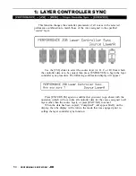
Page 124: ... to begin the layer controller sync procedure The following confirmation display will appear Press ENTER YES again to confirm that you want to go ahead with the operation which will overwrite all controller data for the voices assigned to all layers other than the source layer or press EXIT NO to cancel When the data has been copied Completed will appear briefly on the display then the display wil...

Page 125: ...A and D for example so that the voice with the strong attack is assigned to layer A instead of layer D Since layer A is sounded first the sharpness of the attack will be retained Use the CS7 and CS8 sliders to select the layers to be exchanged A through D then press ENTER YES to begin the layer exchange procedure The following confirmation display will appear Press ENTER YES again to confirm that ...

Page 126: ...y Press ENTER YES to begin the recall procedure The following confirma tion display will appear Press ENTER YES again to confirm that you want to go ahead with the recall operation which will erase all current edited data or press EXIT NO to cancel When the original voice data has been recalled Completed will appear briefly on the display then the display will return to the mode that was en gaged ...

Page 127: ...you choose F7 use the CS8 slider to select the layer you want to initialize Press ENTER YES to begin the initialize procedure The following confir mation display will appear Press ENTFR YES again to confirm that you want to go ahead with the initialize operation which will erase all current edited data or press EXIT NO to cancel When the performance data has been initialized Completed will appear ...

Page 128: ...rily recall the original performance data while editing press the STORE key while holding the SHIFT key The PERFORMANCE LED will flash indicating that the compare mode is engaged Although you can select different edit mode display screens data cannot be edited in the compare mode Press EXIT NO to return to the edit mode and the performance combination being edited 5 4 PERFORMANCE EDIT MODE COMPARE...

Page 129: ... name appears on the upper display line With the cursor in the appropriate position you can use the MEMORY GROUP and NUMBER keys or the corresponding slider to select the memory location to which each voice is to be stored A u appearing next to one of these voice numbers means that the voice is currently used by an other performance combination and therefore any changes to that voice will affect t...

Page 130: ...d Range 82 2 Modulation Wheel Depth 83 3 Foot Controller Depth 85 4 After Touch Depth 87 5 CS3 Parameter Edit 89 6 CS4 Parameter Edit 91 Controller Data Copy 93 7 Voice Total Level 94 8 Voice Name 95 Quick Edit 1 Wave 96 2 Amplitude EG 98 3 Filter 100 4 LFO 102 5 Effect Type 103 6 Effect Parameter 104 Effect Edit 1 Mode Type 105 2 Send Mix Wet Dry 106 3 Output Level 108 4 Effect 1 Parameters 109 5...

Page 131: ... pitch or fixed pitch mode Normally you want the pitch of the AWM wave or waves used in a voice to be controllable from a keyboard or other type of controller in which case the norm mode should be selected In some cases sound effects in particu lar you might want the same pitch to be produced no matter what note you play on the keyboard or other controller In this case the fix mode is appro priate...

Page 132: ...e shifts the pitch down by one octave a setting of 4 shifts the pitch up by a major third Rndm Random pitch Range 0 7 Controls CS7 1 1 Dial Sets the amount of random pitch variation produced each time a note is played When this parameter is set to a value other than 0 the pitch changes randomly each time a note is played The random pitch change is applied independently to each note in a chord A se...

Page 133: ...ial The Atk and Hld mode settings affect the initial attack of the sound determining how the amplitude envelope begins In the Atk mode the enve lope begins from zero level reaching the maximum AWM level at a rate deter mined by the R1 Rate 1 parameter In this mode there will always be a slight delay between the initiation of a note and maximum level R1 RR L2 L3 Rates levels Range 0 63 Controls CS2...

Page 134: ...nvelope begins immediately from maxi mum AWM level allowing the fast attack transients of waveforms to pass unaffected In this case the R1 parameter is replaced by the HT Hold Time parameter The HT parameter determines the length of time between the begin ning of the envelope and the point at which the envelope begins to move towards L2 Level 2 at R2 Rate 2 as shown below For the level parameters ...

Page 135: ...n key or moving the corresponding continuous slider then press the key at which you want to set the breakpoint while holding the SHIFT key No breakpoint can be set to a key lower than the breakpoint to its left Offset 1 4 Range 127 127 Controls CS5 CS8 1 1 Dial Sets the amount of level offset for each of the four level scaling break points set by the Point parameters described above Negative value...

Page 136: ...board dynamics affect the attack time of the amplitude envelope generator Plus settings produce an increase in attack time in proportion to key velocity while minus settings produce a decrease in attack time in propor tion to key velocity The greater the value the greater the change in envelope length RateScaling Range 7 7 Controls CS7 1 1 Dial Allows the overall amplitude envelope generator decay...

Page 137: ...which the source voice is to be selected Use the GROUP keys to select the source voice bank then use the PROGRAM keys to select the source voice number The CS5 slider and other data entry controls can also be used to select the source voice bank and number Once the source voice has been selected press the ENTER YES key Are you sure will appear on the display Press the ENTER YES key again to copy t...

Page 138: ...imbre variations Cutoff Freq Cutoff frequency Range 0 127 Controls CS4 1 1 Dial Sets the cutoff frequency of the selected filter Lower cutoff values produce a lower cutoff frequency and higher values produce a higher cutoff frequency With an LPF response selected by the Type parameter below a lower cutoff frequency reduces the range of high frequencies passed making the sound darker or rounder Wit...

Page 139: ...PF12 settings produces a filter re sponse that allows only frequencies below the cutoff frequency See Cutoff above to pass The LPF filter type has a steep 24 dB octave cutoff slope while the LPF12 type has a gentler 12 dB octave slope HPF Type The HPF High Pass Filter setting produces a filter response that allows only frequencies above the cutoff frequency See Cutoff above to pass 66 VOICE EDIT M...

Page 140: ...esponse that eliminates a band of frequencies centered at the cutoff frequency See Cutoff above to pass The Band parameter below determines the width of the elimination band Band BPF BEF bandwidth Range 0 127 Controls CS6 1 1 Dial Determines the width of the frequency pass or elimination band for the BPF and BEF filter types respectively The minimum setting of 0 produces an extremely narrow pass o...

Page 141: ...w band of frequencies at the filter s cutoff CTRL Filter control Range EG LFO Controls CS8 1 1 Dial Determines whether the cutoff frequency of the selected filter will be con trolled by the LFO or by the filter envelope generator EG Varying the filter cutoff frequency can create sweep or wah wah type effects If the cutoff is controlled via the LFO a cyclic variation based on the shape of the selec...

Page 142: ... moving the corresponding continuous slider then press the key at which you want to set the breakpoint while holding the SHIFT key No breakpoint can be set to a key lower than the breakpoint to its left OFFSET 1 4 Range 127 127 Controls CS5 CS8 1 1 Dial Sets the amount of level offset for each of the four level scaling break points set by the Point parameter described above Negative values lower t...

Page 143: ...meters RS R1 R4 RR1 and RR2 described below are selected for editing L0 L4 RL1 RL2 Levels 0 4 Release levels 1 2 Range 63 63 Controls CS2 CS8 1 1 Dial These parameters are available when the Level Rate switch parameter is set to LVL The level parameters work in conjunction with the rate parameters described below to determine the shape of the cutoff envelope generator for the se lected filter This...

Page 144: ...on R1 R4 RR1 RR2 Rates 1 4 Release rates 1 2 Range 0 63 Controls CS3 CS8 1 1 Dial These parameters work in conjunction with the level parameters described above to determine the shape of the cutoff envelope generator for the selected filter This function is only available if the CTRL parameter page 68 is set to EG The Rate parameters work in the same way as the amplitude and pitch envelope generat...

Page 145: ...mics Plus settings produce higher cutoff frequencies in response to higher velocity values i e the harder a key is played the higher the cutoff fre quency The maximum setting of 63 produces the maximum level variation in response to velocity changes Minus settings produce the opposite effect lower cutoff in response to higher velocity A setting of 0 results in no cutoff variation AtkRateVel Attack...

Page 146: ...y area from which the source voice is to be selected Use the GROUP keys to select the source voice bank then use the PROGRAM keys to select the source voice number The CS5 slider and other data entry controls can also be used to select the source voice number Once the source voice has been selected press the ENTER YES key Are you sure will appear on the display Press the ENTER YES key again to cop...

Page 147: ...R3 RR and RS described below are selected for editing L0 L3 RL1 Levels 0 3 release level 1 Range 63 63 Controls CS3 CS7 1 1 Dial These parameters work in conjunction with the rate parameters described below to determine the shape of the pitch envelope generator for the selected element Unlike the amplitude envelope generator the Level parameters of which actually correspond to volume levels the pi...

Page 148: ... produces the slowest change The pitch envelope begins at L0 Level 0 moves to L1 Level 1 at a rate determined by the setting of R1 then to L2 Level 2 at R2 Rate 2 and then to L3 Level 3 at R3 Rate 3 The pitch stays at L3 until the key is released and then moves to RL1 Release Level 1 at the rate determined by RR Re lease Rate RS Pitch EG rate scaling Range 7 7 Controls CS8 1 1 Dial Allows the over...

Page 149: ...rmines how the overall envelope depth of the pitch envelope generator is controlled by velocity information Plus values produce a deeper pitch envelope in response to higher velocity while minus values produce a shallower pitch envelope in re sponse to higher velocity values The greater the value the greater the change in pitch envelope depth RateVeI Pitch EG rate velocity sensitivity Range 7 7 Co...

Page 150: ...ry area from which the source voice is to be selected Use the GROUP keys to select the source voice bank then use the PROGRAM keys to select the source voice number The CS5 slider and other data entry controls can also be used to select the source voice number Once the source voice has been selected press the ENTER YES key Are you sure will appear on the display Press the ENTER YES key again to co...

Page 151: ...e LFO 0 is the slowest Speed setting producing an LFO speed of approximately 0 Hertz The fastest setting of 99 produces an LFO speed of approximately 25 Hertz Pmod Pitch modulation depth Range 0 127 Controls CS4 1 1 Dial Sets the maximum amount of pitch modulation that can be applied to the current voice A 0 setting produces no modulation while a setting of 127 produces maximum modulation Pitch mo...

Page 152: ...aximum modulation Filter cutoff modulation produces wah wah type effects Please note that the filter cutoff modulation depth parameter for the control ler which is to be used to apply cutoff modulation see page 84 86 and 88 must also be set to an appropriate value before cutoff frequency modulation can be applied Dely Delay Range 0 99 Controls CS7 1 1 Dial Sets the delay time between the beginning...

Page 153: ...nges e g keyboard dynamics Plus settings produce higher LFO speed in response to higher velocity values i e the harder a key is played the higher the LFO speed The maxi mum setting of 7 produces the maximum speed variation in response to velocity changes Minus settings produce the opposite effect lower speed in response to higher velocity A setting of 0 results in no speed variation KeyScale Range...

Page 154: ...ry area from which the source voice is to be selected Use the GROUP keys to select the source voice bank then use the PROGRAM keys to select the source voice number The CS5 slider and other data entry controls can also be used to select the source voice number Once the source voice has been selected press the ENTER YES key Are you sure will appear on the display Press the ENTER YES key again to co...

Page 155: ...allows a maximum pitch bend of plus or minus a major third VolLoLimit Minimum foot volume level Range 0 127 Controls CS5 1 1 Dial Determines the minimum volume level that can be set by the foot volume control If this parameter is set to 0 the minimum foot volume control posi tion will produce no sound A setting of 63 will result in about half volume when the control is set to its minimum position ...

Page 156: ...etting up the low frequency oscillator to apply amplitude modula tion this parameter must be set to a value other than 0 if amplitude modula tion is to be applied via the modulation wheel Pmod Pitch modulation depth Range 0 127 Controls CS5 1 1 Dial Sets the maximum depth of pitch modulation vibrato effects applied via the modulation wheel A setting of 0 allows no pitch modulation while a setting ...

Page 157: ... produced on an acoustic instru ment more accurately than simple volume control A setting of 0 produces no change in EG levels Plus settings produce an increase in level when the modulation wheel is rolled upward and minus settings produce a decrease in level when when the modultion wheel is rolled upward The greater the value the greater the change in level Coff Cutoff frequency depth Range 127 1...

Page 158: ...ile a setting of 127 results in maximum amplitude modulation depth When setting up the low frequency oscillator to apply amplitude modula tion this parameter must be set to a value other than 0 if amplitude modula tion is to be applied via the foot controller Pmod Pitch modulation depth Range 0 127 Controls CS5 1 1 Dial Sets the maximum depth of pitch modulation vibrato effects applied via the foo...

Page 159: ...at can be produced on an acoustic instrument more accurately than simple volume control A setting of 0 produces no change in EG levels Plus settings produce an increase in level when the foot controller is applied and minus settings produce a decrease in level when the foot controller is applied The greater the value the greater the change in level Coff Cutoff frequency depth Range 127 127 Control...

Page 160: ...litude modulation depth When setting up the low frequency oscillator to apply amplitude modula tion this parameter must be set to a value other than 0 if amplitude modula tion is to be applied via keyboard after touch Pmod Pitch modulation depth Range 0 127 Controls CS4 1 1 Dial Sets the maximum depth of pitch modulation vibrato effects applied via keyboard aftertouch A setting of 0 allows no pitc...

Page 161: ...evel when aftertouch is applied and minus set tings produce a decrease in level when aftertouch is applied The greater the value the greater the change in level Coff Cutoff frequency depth Range 127 127 Controls CS7 1 1 Dial Sets the maximum depth of filter cutoff frequency variation applied via keyboard aftertouch Plus settings produce higher cutoff frequencies in response to aftertouch i e the g...

Page 162: ...ated with each voice parameter are listed below CS3 PARAMETER LIST 0 39 6 0 No_Assign 1 CT_MW_Pmod 2 CT_MW_Amod 3 CT_MW_Fmod 4 CT_MW_Coff 5 CT_MW_EGBs 7 CT_FC_Pmod CT_FC_Amod 8 CT_FC_Fmod 9 CT_FC_Coff 10 CT_FC_EGBs 11 CT_AT_Pmod 12 CT_AT_Amod 13 CT_AT_Fmod 14 CT_AT_Coff 15 CT_AT_EGBs 16 CT_AT_PtBs 17 CT_PBRange 18 CT_VLLoLim 19 TotalLevel 20 EF_SendLvl 21 OS_FrqFine 22 OS_Random 23 PEG_Rate1 24 PE...

Page 163: ...MIDI control change data using control number 18 Min Range 0 100 Controls CS6 1 1 Dial Sets the lower limit of the CS3 control range A setting of 0 for exam ple means that when the CS3 slider is set to its lowest position the assigned parameter will also be set to its lowest value A setting of 50 means that the lowest CS3 position will set the assigned parameter to about 50 of its range a paramete...

Page 164: ...ated with each voice parameter are listed below CS4 PARAMETER LIST 0 39 0 No_Assign 1 CT_MW_Pmod 2 CT_MW_Amod 3 CT_MW_Fmod 4 CT_MW_Coff 5 CT_MW_EGBs 6 CT_FC_Pmod 7 CT_FC_Amod 8 CT_FC_Fmod 9 CT_FC_Coff 10 CT_FC_EGBs 11 CT_AT_Pmod 12 CT_AT_Amod 13 CT_AT_Fmod 14 CT_AT_Coff 15 CT_AT_EGBs 16 CT_AT_PtBs 17 CT_PBRange 18 CT_VLLoLim 19 TotalLevel 20 EF_Sendlvl 21 OS_FrqFine 22 OS_Random 23 PEG_Rate1 24 PE...

Page 165: ... using control number 19 Min Minimum parameter value Range 0 100 Controls CS6 1 1 Dial Sets the lower limit of the CS4 control range A setting of 0 for exam ple means that when the CS4 slider is set to its lowest position the assigned parameter will also be set to its lowest value A setting of 50 means that the lowest CS4 position will set the assigned parameter to about 50 of its range a paramete...

Page 166: ...ch the source voice is to be selected Use the GROUP keys to select the source voice bank then use the PROGRAM keys to select the source voice number The CS5 slider and other data entry controls can also be used to select the source voice number Once the source voice has been selected press the ENTER YES key Are you sure will appear on the display Press the ENTER YES key again to copy the controlle...

Page 167: ...hing between voices Total Level Range 0 127 Controls CS4 1 1 Dial Adjusts the volume of the current voice A setting of 0 produces no sound while a setting of 127 produces maximum volume A bar graph to the right of the parameter provides a visual indication of volume level the longer the bar the higher the volume 94 VOICE EDIT MODE 7 Total Level ...

Page 168: ...nd PROGRAM key selects the three characters printed above it in sequence It is also possible to use the 1 and 1 keys or dial to scroll through the avail able characters see list below The sliders CS1 through CS8 independently select characters for the corresponding character position CS1 selects the first character CS2 selects the second character and so on The first four function keys also perfor...

Page 169: ...e categories or groups each containing a number of waves that can be individually selected by using the Number parameter below Quick Edit 1 Piano 2 Key 3 Brass 4 Wind 5 Strings 6 A Guitar 7 E Guitar 8 Bass 9 Folk 10 Synth 11 Choir 12 TPerc 13 Drum 14 Perc 15 SE 16 Osc Wave Groups Acoustic pianos Other keyboards Brass instruments Wind instruments Strings Acousticguitars Electric guitars Acoustic el...

Page 170: ...oice Use the Group parameter above to select the group containing the wave that is to be selected The INTERNAL 1 INTERNAL 2 and CARD keys can also be used to select the memory area from which the wave is to be selected A complete listing of the internal waves is given in the Appendix on page 310 VOICE EDIT MODE QUICK EDIT 97 ...

Page 171: ... types for the current voice The envelope types are Quick Edit Envelope Types 00 01 Piano 02 Brass 03 SfzBrass 04 SynBrass 05 StFast 06 StSlw Pd 07 E Bass 08 SynBass1 09 SynBass2 10 Organ 11 Guitar 12 Pluck1 13 Pluck2 14 SynPad 15 SynComp 16 Percusiv 17 S ldeal1 18 S ldeal2 19 S ldeal3 20 S ldeal4 21 Init Full edit envelope Acoustic piano Brass Sforzando brass Synthesizer brass Fast attack strings...

Page 172: ...e Velo Velocity sensitivity Range 7 7 Controls CS8 1 1 Dial Determines how the output level of the current voice changes in response to velocity changes e g keyboard dynamics Plus settings produce higher output level in response to higher velocity values i e the harder a key is played the louder the sound The maximum setting of 7 produces the maximum level variation in response to velocity changes...

Page 173: ...tive hard response 4 VeloReso Velocity sensitive resonant 5 SynBass1 Synthesizer bass 1 6 SynBass2 Synthesizer bass 2 7 SynBras1 Synthesizer brass 1 8 SynBras2 Synthesizer brass 2 9 Sweep Sweep frequency filter 10 SlowAtak Slow attack filter 11 LPF_lnit Initialized LPF 12 HPF_lnit Initialized HPF 13 BPF_Init Initialized BP 14 BEF_Init Initialized BEF 15 Thru No filter Coff Cutoff frequency Range 0...

Page 174: ...ce the overall bandwidth of the filter passing a narrow band of frequencies at the filter s cutoff Vel Velocity sensitivity Range 63 63 Controls CS8 1 1 Dial Determines how the filter cutoff frequency changes in response to velocity changes e g keyboard dynamics Plus settings produce higher cutoff frequencies in response to higher velocity values i e the harder a key is played the higher the cutof...

Page 175: ...parameter settings page 78 are selected when this parameter is set to Speed Range 0 99 Controls CS5 1 1 Dial Sets the speed of the LFO 0 is the slowest speed setting producing an LFO speed of approximately 0 Hertz The fastest setting of 99 produces an LFO speed of approximately 25 Hertz Depth Range 0 127 Controls CS6 1 1 Dial Sets the maximum amount of amplitude tremolo pitch vibrato or filter cut...

Page 176: ...ntrols CS1 CS4 1 1 Dial CS1 selects any of the SY85 s 90 effect types for the EFFECT 1 proces sor and CS4 does the same for the EFFECT 2 processor See page 254 for more details on the SY85 effect system Wet Balance Range 0 100 Controls CS8 1 1 Dial CS8 controls the balance between the direct no effect sound and the effect sound delivered via the OUTPUT 1 jacks The maximum setting of 100 produces m...

Page 177: ... four effect 1 parameters are edited via CS1 through CS4 while the four effect 2 parameters are edited via CS5 through CS8 The parameters are different for each effect refer to page 274 for details The EFFECT mode PARAMETERS screen described on page 109 provides full access to all 8 effect parameters 104 VOICE EDIT MODE QUICK EDIT ...

Page 178: ... or in parallel 2 para or whether the entire effect system is turned off 0 off EF1 Type Range 0 90 Controls CS3 1 1 Dial Selects any of the SY85 s 90 effect types for the EFFECT 1 processor See page 254 for more details on the SY85 effect system and page 274 for a complete list of the available effects EF2 Type Range 0 90 Controls CS6 1 1 Dial Selects any of the SY85 s 90 effect types for the EFFE...

Page 179: ...s parameter can only be used with the serial effect mode is selected If any other mode is selected off or para appears on the display in place of the value If a controller is assigned to the EF2 Mix parameter page 110 an inverse c will appear to the right of the parameter Out1 Wet Range 0 100 Controls CS7 1 1 Dial This parameter and the Out1 Dry parameter below work together to balance the effect ...

Page 180: ...ffect wet and direct dry signals delivered via the OUTPUT 1 jacks Higher Out1 Dry values produce more direct dry sound in relation to the effect sound Although the Wet and Dry parameters can be set independently adjust ing one will cause the other to change so that their total is always 100 VOICE EDIT MODE EFFECT EDIT 107 ...

Page 181: ...e off while a setting of 100 produces maximum output level If the selected effect is a single type then only the 1a or 2a output level is available If it is a cascade type then only the 1b or 2b output level is available Both the 1a and 1b or 2a and 2b levels are available only if the selected effect is a dual type The type of the effects currently selected for the effect 1 and effect 2 processors...

Page 182: ...e tune the effect Each parameter is controlled by the corresponding slider i e the slider immedi ately below each parameter The 1 1 keys and data entry dial can also be used to edit the parameter at which the cursor is currently located Refer to page 274 for a complete listing of the parameters provided for each effect VOICE EDIT MODE EFFECT EDIT 109 ...

Page 183: ...meter will be 8 Ef1prm1 through Ef1prm8 on the display for example stands for effect 1 parameter 1 through effect 1 parameter 8 The parameters available for each effect are different but the name of the selected parameter will be shown between the parentheses on the top line of the display Parameters that can not be assigned to the sliders are indicated by dashes instead of a parameter name Min Mi...

Page 184: ...y can be controlled from the SY85 con trollers modulation wheel foot controller etc or an external MIDI device that is capable of transmitting control change messages Additional settings include AfterTch for keyboard aftertouch control Velocity for keyboard velocity control KeyScale for key scaling control and LFO for internal LFO con trol This is in addition to control via the CS1 and CS2 sliders...

Page 185: ...of the effect LFO 0 is the slowest Speed setting producing an LFO speed of approximately 0 Hertz The fastest setting of 99 produces an LFO speed of approximately 25 Hertz If a controller is assigned to the Speed parameter page 110 an inverse c will appear to the right of the parameter Delay Range 0 99 Controls CS8 1 1 Dial Sets the delay time between the beginning of a note and the beginning of ef...

Page 186: ... MLT MULTI Use the INTERNAL 1 INTERNAL 2 and CARD MEMORY keys to select the memory area from which the source voice is to be selected Use the GROUP keys to select the source voice bank then use the PROGRAM keys to select the source voice number The CS5 slider and other data entry controls can also be used to select the source voice number Once the source voice has been selected press the ENTER YES...

Page 187: ...nfiguration Effect 2 Configuration Press SHIFT F1 to see the overall effect system signal flow Press SHIFT F2 to see the effect 1 section configuration and SHIFT F3 for the effect 2 section configuration Press the EXIT NO key to exit from the effect signal flow display Refer the to section beginning on page 254 for details on the effect system 114 VOICE EDIT MODE EFFECT EDIT ...

Page 188: ...TER YES to begin the recall procedure The following confirma tion display will appear Press ENTER YES again to confirm that you want to go ahead with the recall operation which will erase all current edited data or press EXIT NO to cancel When the original voice data has been recalled Completed will appear briefly on the display then the display will return to the mode that was en gaged prior to c...

Page 189: ...The following confir mation display will appear Press ENTER YES again to confirm that you want to go ahead with the initialize operation which will erase all current edited data or press EXIT NO to cancel When the voice data has been initialized Completed will appear briefly on the display then the display will return to the mode that was engaged prior to calling the voice initialize function 116 ...

Page 190: ...or to editing To temporarily recall the original voice while editing press the STORE key while holding the SHIFT key The VOICE LED will flash indicating that the compare mode is engaged Data cannot be edited in the compare mode Press EXIT NO again to return to the edit mode and the voice being edited VOICE EDIT MODE COMPARE 117 ...

Page 191: ...to select the memory location to which your new voice is to be stored Once the store location has been specified press ENTER YES to begin the store procedure The following confirmation display will appear Press ENTER YES again to confirm that you want to go ahead with the store operation which will erase all previous data in the specified memory location or press EXIT NO to cancel When the voice d...

Page 192: ...tal Level 123 4 Drum Voice Name 124 Drum Key Data Copy 125 Quick Edit Effect Edit 1 Mode Type 128 2 Key Send Select Level 129 3 Key Dry Output Select 131 4 Output Level 132 5 Wet Dry Balance 133 Send Effect 2 Mix Level 134 7 Effect 1 Parameter2 135 8 Effect 2 Parameter2 135 9 Control Parameters 136 10 Control LFO 138 Effect Data Copy 139 Effect Signal Flow Display 140 145 Effect Send Level 127 Dru...

Page 193: ...rea from which the wave is to be selected A complete listing of the internal waves is given in the Appendix on page 310 Vol Range 0 127 Controls CS5 1 1 Dial For optimum balance between the instruments in a drum kit this param eter allows the volume of the current drum key to be adjusted independently A setting of 0 produces no sound while a setting of 127 produces maximum volume Nsft Range 48 36 ...

Page 194: ...of 0 produces no pitch change Pan Range 31 31 Controls CS8 1 1 Dial Interesting stereo effects can be produced by placing the sound of different drum instruments at different locations in the stereo sound field This parameter determines the position in the stereo sound field in which the sound from the current drum key will be heard left to right Minus values represent panning to the left and posi...

Page 195: ...ame alter nate group so that when the closed hi hat key is played the open hi hat sound is immediately cut off Turn this parameter off if you don t want the current drum key to be assigned to any alternate group GateTime Range short normal long very long Controls CS6 1 1 Dial Sets the length of the note played by the selected drum key to short nor mal long or very long Please note that this parame...

Page 196: ...h beside the parameter provides a visual indica tion of volume level the longer the bar the higher the volume VolLoLimit Minimum volume level Range 0 127 Controls CS6 1 1 Dial Determines the minimum volume level that can be set by the foot volume control MIDI volume control data If this parameter is set to 0 the minimum foot volume control position will produce almost no sound A setting of 63 will...

Page 197: ... in sequence It is also possible to use the 1 and 1 keys or dial to scroll through the available characters see list below The sliders CS1 through CS8 independently select characters for the corresponding character position CS1 selects the first character CS2 selects the second character and so on The first four function keys also perform important functions F1 clears the entire name F2 selects up...

Page 198: ...lso be selected by simply pressing the appropriate key on the keyboard after plac ing the cursor at the From or To parameter position by pressing the F5 or F7 function key respectively The names of the waves currently assigned to the From and To keys are displayed above the key numbers Once the source and destination keys have been selected press the EN TER YES key Are you sure will appear on the ...

Page 199: ...85 s 90 effect types for the EFFECT 1 proces sor and CS4 does the same for the EFFECT 2 processor See page 254 for more details on the SY85 effect system Wet Balance 1 2 Range 0 100 Controls CS7 CS8 1 1 Dial CS7 controls the balance between the direct no effect sound and the effect sound of the EFFECT 1 processor while CS8 does the same for the EFFECT 2 processor The higher the value the deeper th...

Page 200: ...um effect sound Key Range C1 C5 Controls CS2 1 1 Dial keyboard Selects the drum key C1 C5 for which the send level is to be adjusted Use either the CS2 slider or the keyboard to enter the key number Send Level Range 0 127 Controls CS4 1 1 Dial Sets the effect send level for the selected drum key DRUM VOICE EDIT MODE QUICK EDIT 127 ...

Page 201: ... in parallel 2 para or whether the entire effect system is turned off 0 off EF1 Type Range 0 90 Controls CS3 1 1 Dial Selects any of the SY85 s 90 effect types for the EFFECT 1 processor See page 254 for more details on the SY85 effect system and page 274 for a complete list of the available effects EF2 Type Range 0 90 Controls CS6 1 1 Dial Selects any of the SY85 s 90 effect types for the EFFECT ...

Page 202: ...es the output from the current layer is sent Each time the F5 or F6 function key is pressed the cursor alternately moves to the corresponding a or b parameter The 1 and 1 keys can then be used to turn the stage on a or b or off The CS5 and CS6 sliders select the following settings in sequence CS5 EFFECT 1 CS6 EFFECT 2 1 a and b off 2 a and b off 1a a on b off 2a a on b off 1a b a and b on 2a b a a...

Page 203: ... Controls CS8 1 1 Dial Determines how the send level from the selected drum key is affected by velocity changes e g keyboard dynamics Plus settings produce higher send levels in response to higher velocity values i e the harder a key is played the higher the send level and there fore the deeper the effect The maximum setting of 7 produces the maxi mum level variation in response to velocity change...

Page 204: ...igned to the selected key is shown between parentheses on the upper line of the display Dry1 Range off on Controls CS6 1 1 Dial Turns the dry line bypassing the EFFECT 1 signal processor on or off When this parameter is turned off the WET DRY BALANCE parameters page 133 have no effect Dry2 Range off on Controls CS7 1 1 Dial Turns the dry line bypassing the EFFECT 2 signal processor on or off When ...

Page 205: ...ff while a setting of 100 produces maximum output level If the selected effect is a single type then only the la or 2a output level is available If it is a cascade type then only the 1b or 2b output level is available Both the 1a and 1b or 2a and 2b levels are available only if the selected effect is a dual type The type of the effects currently selected for the effect 1 and effect 2 processors ar...

Page 206: ...t ing one will cause the other to change so that their total is always 100 If a controller is assigned to the Out1 Wet or Out2 Wet parameter page 136 an inverse c will appear to the right of the parameter Out2 Dry Out2 Dry Range 0 100 Controls CS4 CS8 1 1 Dial These parameters and the corresponding Out1 Wet and Out2 Wet pa rameters above work together to balance the effect wet and direct dry signa...

Page 207: ... appears on the display in place of the value If a controller is assigned to the EF2 Mix parameter page 136 an inverse c will appear to the right of the parameter Send 1b 2a 2b Send level Range 0 100 Controls CS6 CS7 CS8 1 1 Dial These parameters mix the dry signal sent to the corresponding effect stage with the output of the preceding effect stage The higher the value the greater mix level If the...

Page 208: ...tune the effect Each parameter is controlled by the corresponding slider i e the slider immediately below each parameter The 1 1 keys and data entry dial can also be used to edit the parameter at which the cursor is currently located Refer to page 274 for a complete listing of the parameters provided for each effect DRUM VOICE EDIT MODE EFFECT EDIT 135 ...

Page 209: ...er will be 8 Ef1prm1 through Ef1prm8 on the display for example stands for effect 1 parameter 1 through effect 1 parameter 8 The parameters available for each effect are different but the name of the selected parameter will be shown between the parentheses on the top line of the display Parameters that can not be assigned to the sliders are indicated by dashes instead of a parameter name Min Minim...

Page 210: ...can be controlled from the SY85 con trollers modulation wheel foot controller etc or an external MIDI device that is capable of transmitting control change messages Additional settings include AfterTch for keyboard aftertouch control Velocity for keyboard velocity control KeyScale for key scaling control and LFO for internal LFO con trol This is in addition to control via the CS1 and CS2 sliders M...

Page 211: ...ts the speed of the effect LFO 0 is the slowest speed setting producing an LFO speed of approximately 0 Hertz The fastest setting of 99 produces an LFO speed of approximately 25 Hertz If a controller is assigned to the Speed parameter page 136 an inverse c will appear to the right of the parameter Delay Range 0 99 Controls CS8 1 1 Dial Sets the delay time between the beginning of a note and the be...

Page 212: ... MLT MULTI Use the INTERNAL 1 INTERNAL 2 and CARD MEMORY keys to select the memory area from which the source voice is to be selected Use the GROUP keys to select the source voice bank then use the PROGRAM keys to select the source voice number The CS5 slider and other data entry controls can also be used to select the source voice number Once the source voice has been selected press the ENTER YES...

Page 213: ...erall Effect Flow l l Effect 1 Configuration l l Effect 2 Configuration Press SHIFT F1 to see the overall effect system signal flow Press SHIFT F2 to see the effect 1 section configuration and SHIFT F3 for the effect 2 section configuration Refer the to section beginning on page 254 for details on the effect system 140 DRUM VOICE EDIT MODE EFFECT EDIT ...

Page 214: ...ss ENTER YES to begin the initialize proce dure The following confirmation display will appear Press ENTER YES again to confirm that you want to go ahead with the initialize operation which will erase all current edited data or press EXIT NO to cancel When the drum key data has been initialized Completed will appear briefly on the display then the display will return to the mode that was en gaged ...

Page 215: ...nction key to move the cursor to the appropriate parameter Press ENTER YES to begin the layer exchange procedure The following confirmation display will appear Press ENTER YES again to confirm that you want to go ahead with the key data exchange operation or press EXIT NO to cancel When the data has been exchanged Completed will appear briefly on the display then the display will return to the mod...

Page 216: ...S to begin the recall procedure The following confirma tion display will appear Press ENTER YES again to confirm that you want to go ahead with the recall operation which will erase all current edited data or press EXIT NO to cancel When the original drum voice data has been recalled Completed will appear briefly on the display then the display will return to the mode that was engaged prior to cal...

Page 217: ...egin the initialize procedure The following confirmation display will appear Press ENTER YES again to confirm that you want to go ahead with the initialize operation which will erase all current edited data or press EXIT NO to cancel When the drum voice data has been initialized Completed will appear briefly on the display then the display will return to the mode that was en gaged prior to calling...

Page 218: ... recall the original drum voice data while editing press the STORE key while holding the SHIFT key The VOICE LED will flash indicat ing that the compare mode is engaged Although you can select different edit mode display screens data cannot be edited in the compare mode Press EXIT NO to return to the edit mode and the drum voice being edited DRUM VOICE EDIT MODE COMPARE 145 ...

Page 219: ... to select the memory location to which your new drum voice is to be stored Once the store location has been specified press ENTER YES to begin the store procedure The following confirmation display will appear Press ENTER YES again to confirm that you want to go ahead with the store operation which will erase all previous data in the specified memory location or press EXIT NO to cancel When the v...

Page 220: ...Send Effect 2 Mix Level 172 7 Effect 1 Parameters 173 8 Effect 2 Parameters 173 9 Control Parameters 174 10 Control LFO 176 Effect Data Copy 177 Effect Signal Flow Display 178 Job 1 Clear Song 179 2 Copy Song 180 3 Memory Status Clear Rhythm Track 181 182 4 Track Mixdown 183 5 Delete Track 185 6 Quantize 186 7 Copy Measure 188 8 Delete Measure 190 9 Insert Measure 191 10 Erase Measure 192 11 Remov...

Page 221: ...f voices is indicated on the upper display line After moving the cursor to the instrument you want to edit by pressing the appropriate function key use the same function key to toggle between PER FORMANCE or VOICE memory P or V at the beginning of the voice number Then use the INTERNAL 1 INTERNAL 2 and CARD keys to select the memory area from which the voice is to be selected and finally the GROUP...

Page 222: ... selected group of voices is indicated on the upper display line Use the CS1 through CS8 sliders to adjust the volume levels of voices 1 through 8 or 9 through 16 respectively The name of the currently selected voice is shown in the upper right corner of the display Voices that are turned off are indicated by on the display A setting of 0 produces no sound while a setting of 127 produces maximum v...

Page 223: ...rs to adjust the pan positions of voices 1 through 8 or 9 through 16 respectively The name of the currently selected voice is shown in the upper right corner of the display Voices that are turned off are indicated by on the display Minus values represent panning to the left and positive values represent panning to the right 0 positions the sound of the selected layer in the center of the stereo so...

Page 224: ...voices 1 through 8 or 9 through 16 respectively The name of the currently selected voice is shown in the upper right corner of the display Voices that are turned off are indicated by on the display A setting of 0 produces no effect while a setting of 127 produces maximum send level and therefore maximum effect sound The vertical bar graphs next to each parameter provide a visual indication of send...

Page 225: ...tch of voices 1 through 8 or 9 through 16 respectively The name of the currently selected voice is shown in the upper right corner of the display Voices that are turned off are indicated by on the display A setting of 12 for example shifts the pitch of the selected layer down by one octave a setting of 4 shifts the pitch up by a major third Please note that note shift cannot be applied to drum per...

Page 226: ...play line Use the CS1 through CS8 sliders to fine tune voices 1 through 8 or 9 through 16 respectively The name of the currently selected voice is shown in the upper right corner of the display Voices that are turned off are indicated by on the display Each increment corresponds to approximately 1 17 cents a cent is 1 100th of a semitone The maximum minus setting of 63 produces a downward pitch sh...

Page 227: ...of the SY85 s 90 effect types for the EFFECT 1 proces sor and CS4 does the same for the EFFECT 2 processor See page 254 for more details on the SY85 effect system Wet Balance 1 2 Range 0 100 Controls CS7 CS8 1 1 Dial CS7 controls the balance between the direct no effect sound and the effect sound of the EFFECT 1 processor while CS8 does the same for the EFFECT 2 processor The higher the value the ...

Page 228: ...sequence It is also possible to use the 1 and 1 keys or dial to scroll through the available characters see list below The sliders CS1 through CS8 independently select characters for the corresponding character position CS1 selects the first character CS2 selects the second character and so on The first four function keys also perform important functions F1 clears the entire name F2 selects upper ...

Page 229: ...The following confir mation display will appear Press ENTER YES again to confirm that you want to go ahead with the initialize operation which will erase all current edited data or press EXIT NO to cancel When the multi data has been initialized Completed will appear briefly on the display then the display will return to the mode that was engaged prior to calling the multi initialize function 156 ...

Page 230: ... or inserted as required providing precise musical control The track edit mode has two sub modes change and insert which will be described below Use the F1 key to toggle between the change CHG on the display and insert INS on the display modes The change mode is always selected when the track edit mode is initially engaged SONG EDIT MODE TRACK EDIT 157 ...

Page 231: ...cated use the appropriate slider to change it as required or move the cursor to the desired parameter by pressing the corresponding function key and then use the and keys The selected event can be erased by pressing the F8 key Top of Track Measure Bar and End of Track can not be deleted After changing a value the ENTER YES key must be pressed to actu ally enter the new value THE CHANGE MODE Tracks...

Page 232: ...he upper display line while the corresponding length in clocks is shown on the lower line l l The velocity of the note edited by CS7 Range 1 ppp 127 fff The velocity is displayed in approximate musical dynamic markings on the upper display line while the corresponding MIDI velocity value is shown on the lower line l l Control Change Control change events appear with 2 parameters l l The control nu...

Page 233: ...ce change l l Pitch Bend Pitch change events appear with a single parameter the new pitch bend value edited via CS6 Range 64 63 l l Aftertouch Aftertouch events appear with a single parameter the new aftertouch value edited via CS6 Range 0 127 The effect of aftertouch events depends on how aftertouch control is assigned in the voice edit mode 160 SONG EDIT MODE TRACK EDIT ...

Page 234: ...nth note and so on If the Top of Track Measure Bar or End of Track display is show ing changing these parameters and pressing the ENTER YES key takes you directly to the specified location n n THE INSERT MODE Tracks 1 8 SONG EDIT MODE TRACK EDIT 161 Insert edit INS allows note control change program change pitch bend and aftertouch events to be inserted at any point in the sequencer tracks Normall...

Page 235: ...t types and their parameters are as follows ptn Pattern number Use CS4 to select a different pattern number as required P00 P99 or I00 I99 Begin repeat This symbol indicates the beginning of a range of rhythm parts to be re peated The begin repeat event has no other parameter End repeat A must always be followed at some point by a symbol signifying the end of the range of parts to be repeated Use ...

Page 236: ... the marker A P The F5 through F8 function keys are used to access the rhythm track edit functions described below l l F5 INS Rhythm Track Insert This function is used to insert a new part at any point in an existing rhythm track Press F5 to engage the rhythm track insert function after locating the desired insert point via the main rhythm track edit screen described above Then use CS3 and CS4 to ...

Page 237: ...appear briefly on the display then the display will return to the main rhythm track edit mode l F7 CPY Rhythm Track Copy This function is used to copy a part or a range of parts to any other point in a rhythm track Press F7 to engage the rhythm track copy function Then use CS6 to select the number of the first part in the range of parts to be copied 001 999 CS7 to select the number of the last par...

Page 238: ...ctly locate marks entered in the track using the mark event in the main rhythm track edit screen The SHIFT key is used to toggle between marks A through H and I through G Square brackets appear around marks that exist within the rhythm track To go directly to a marked location simply press the function key immediately below the desired mark The main rhythm track edit screen will appear with the ma...

Page 239: ... or in parallel 2 para or whether the entire effect system is turned off 0 off EF1 Type Range 0 90 Controls CS3 1 1 Dial Selects any of the SY85 s 90 effect types for the EFFECT 1 processor See page 254 for more details on the SY85 effect system and page 274 for a complete list of the available effects EF2 Type Range 0 90 Controls CS6 1 1 Dial Selects any of the SY85 s 90 effect types for the EFFE...

Page 240: ...he Source parameter can also be set to VCE causing the switch and send levels of the assigned voice to be used In the same way if a performance combination is assigned to the selected instrument the Source parameter can be set to PFM causing the switch and send levels of the assigned performance combination to be used If VCE or PFM is se lected the Switch and Lev1 parameters cannot be edited appea...

Page 241: ...l type effect is selected then both stages a and b can be selected An effect stage that cannot be selected is represented by on the display Levl Send level Range 0 127 Controls CS8 1 1 Dial This parameter adjusts the amount of direct voice signal that is sent to the effect processors determining the strength of the final effect sound A setting of 0 results in no effect leaving only the dry sound T...

Page 242: ...splay Dry1 Range off on Controls CS6 1 1 Dial Turns the dry line bypassing the EFFECT 1 signal processor on or off When this parameter is turned off the WET DRY BALANCE parameters page 171 have no effect Dry2 Range off on Controls CS7 1 1 Dial Turns the dry line bypassing the EFFECT 2 signal processor on or off When this parameter is turned off the WET DRY BALANCE parameters page 171 have no effec...

Page 243: ...e off while a setting of 100 produces maximum output level If the selected effect is a single type then only the 1a or 2a output level is available If it is a cascade type then only the 1b or 2b output level is available Both the 1a and 1b or 2a and 2b levels are available only if the selected effect is a dual type The type of the effects currently selected for the effect 1 and effect 2 processors...

Page 244: ...djust ing one will cause the other to change so that their total is always 100 If a controller is assigned to the Out1 Wet or Out2 Wet parameter page 174 an inverse c will appear to the right of the parameter Out1 Dry Out2 Dry Range 0 100 Controls CS4 CS8 1 1 Dial These parameters and the corresponding Out1 Wet and Out2 Wet pa rameters above work together to balance the effect wet and direct dry s...

Page 245: ...d off or para display in place of the value If a controller is assigned to the EF2 Mix parameter page 74 an inverse c will appear to the right of the parameter Send 1b 2a 2b Send level Range 0 100 Controls CS6 CS7 CS8 1 1 Dial These parameters mix the dry signal sent to the corresponding effect stage with the output of the preceding effect stage The higher the value the greater mix level If the cu...

Page 246: ...ne tune the effect Each parameter is controlled by the corresponding slider i e the slider immediately below each parameter The 1 1 keys and data entry dial can also be used to edit the parameter at which the cursor is currently located Refer to page 274 for a complete listing of the parameters provided for each effect SONG EDIT MODE SONG EFFECT 173 ...

Page 247: ...fect 1 parameter 1 through effect 1 parameter 8 The parameters available for each effect are different but the name of the selected parameter will be shown between the parentheses on the top line of the display Parameters that can not be assigned to the sliders are indicated by dashes instead of a parameter name Min Minimum parameter value Range 0 100 Controls CS4 1 1 Dial Sets the lower limit of ...

Page 248: ... can be controlled from the SY85 con trollers modulation wheel foot controller etc or an external MIDI device that is capable of transmitting control change messages Additional settings include AfterTch for keyboard aftertouch control Velocity for keyboard velocity control KeyScale for key scaling control and LFO for internal LFO con trol This is in addition to control via the CS1 and CS2 sliders ...

Page 249: ... Sets the speed of the effect LFO 0 is the slowest speed setting producing an LFO speed of approximately 0 Hertz The fastest setting of 99 produces an LFO speed of approximately 25 Hertz If a controller is assigned to the Speed parameter page 174 an inverse c will appear to the right of the parameter Delay Range 0 99 Controls CS8 1 1 Dial Sets the delay time between the beginning of a note and the...

Page 250: ...LTI Use the INTERNAL 1 INTERNAL 2 and CARD MEMORY keys to select the memory area from which the source voice is to be selected Use the GROUP keys to select the source voice bank then use the PROGRAM keys to select the source voice number The CS5 slider and other data entry controls can also be used to select the source voice number Once the source voice has been selected press the ENTER YES key Ar...

Page 251: ... Overall Effect Flow l l Effect 1 Configuration l l Effect 2 Configuration Press SHIFT F1 to see the overall effect system signal flow Press SHIFT F2 to see the effect 1 section configuration and SHIFT F3 for the effect 2 section configuration Refer the to section beginning on page 254 for details on the effect system 178 SONG EDIT MODE SONG EFFECT ...

Page 252: ...ses on the lower display line Press ENTER YES to begin the clear procedure The following confirma tion display will appear Press ENTER YES again to confirm that you want to go ahead with the clear operation or press EXIT NO to cancel When the song data has been cleared Completed will appear briefly on the display In addition to clearing all sequencer data for the current song the clear function in...

Page 253: ...To or desination song number The name of the currently selected From or To song is shown between parentheses on the lower display line depending on which parameter the cursor is positioned below Press ENTER YES to begin the copy procedure The following confirma tion display will appear Press ENTER YES again to confirm that you want to go ahead with the copy operation which will overwrite all data ...

Page 254: ...play of Free 80 for example means that approximately 20 of the available memory has been used and approximately 80 is available for further recording A Memory full error message may appear during recording even if this function does not indicate Free 0 This is because a certain amount of free work area is required by each function and the memory can never be occu pied entirely by song data SONG ED...

Page 255: ...m track track 9 is selected Press ENTER YES to begin the delete procedure The following confirma tion display will appear Press ENTER YES again to confirm that you want to go ahead with the delete operation or press EXIT NO to cancel When the rhythm track has been deleted Completed will appear briefly on the display 182 SONG EDIT MODE RHYTHM TRACK SONG JOB ...

Page 256: ...ocedure The following confir mation display will appear Press ENTER YES again to confirm that you want to go ahead with the mixdown operation which will overwrite all data in the To track or press EXIT NO to cancel When the data has been mixed and copied Completed will appear briefly on the display The mixdown function is most useful when you want to record more than 8 individual parts Successfull...

Page 257: ...184 SONG EDIT MODE SONG JOB ...

Page 258: ...o on The LED of the selected track will glow red while the LEDs of all other tracks containing data glow green Press EN TER YES to begin the delete procedure The following confirmation display will appear Press ENTER YES again to confirm that you want to go ahead with the delete operation or press EXIT NO to cancel When the track has been deleted Completed will appear briefly on the display SONG E...

Page 259: ...ED of the selected track will glow red while the LEDs of all other tracks containing data glow green Use the CS6 and CS7 sliders to select the numbers of the first and last measures in the range of measures you want to quantize and use the CS8 slider to select the quantize size Press ENTER YES to begin the quantize procedure The following confir mation display will appear Press ENTER YES again to ...

Page 260: ... aiming for a cold mechanical feel Always use a quantize value that is at least as short as the shortest notes in the track to be quantized If you quantize a track containing 16th notes to 1 8 8th notes for example some of the 16th notes will be aligned with 8th note beats thus ruining the track The various quantize values correspond to note lengths as follows SONG EDIT MODE SONG JOB 187 ...

Page 261: ...the range to be copied and CS3 to specify the number of times the selected data is to be copied Use CS7 to specify the destination track and CS8 to specify the destination measure Press ENTER YES to begin the copy procedure The following confirma tion display will appear 188 Press ENTER YES again to confirm that you want to go ahead with the copy operation which will overwrite data in the destinat...

Page 262: ...SONG EDIT MODE SONG JOB 189 ...

Page 263: ...asures you want to delete Press ENTER YES to begin the delete procedure The following confirma tion display will appear Press ENTER YES again to confirm that you want to go ahead with the delete operation or press EXIT NO to cancel When the data has been deleted Completed will appear briefly on the display It s important to remember that a delete operation affects all tracks simulta neously and th...

Page 264: ...es in the range to be copied and CS8 to select the destination measure number at which the source data will be inserted Press ENTER YES to begin the insert procedure The following confirma tion display will appear Press ENTER YES again to confirm that you want to go ahead with the insert operation or press EXIT NO to cancel When the data has been inserted Completed will appear briefly on the displ...

Page 265: ... the selected track will glow red while the LEDs of all other tracks containing data glow green Use the CS7 and CS8 sliders to select the numbers of the first and last measures in the range of measures you want to erase Press ENTER YES to begin the erase procedure The following confirma tion display will appear Press ENTER YES again to confirm that you want to go ahead with the erase operation or ...

Page 266: ...ontaining data glow green Use CS5 to select the type of event to remove ctrl for control change pgm for program change AT for aftertouch and PB for pitch bend Removing a program change pgm event also removes control change number 0 and 32 bank select If ctrl is selected CS6 can be used to specify a control number to be removed see below Use the CS7 and CS8 sliders to select the numbers of the firs...

Page 267: ...ant to remove For your reference the following is a list of assigned controllers MIDI 0 1 2 4 5 6 7 8 10 11 64 65 66 67 69 CONTROL CHANGE Mod Whl Breath C Foot Cnt Porta Tm Data Ent Main Vol Balance Panpot Express Hold 1 Porta Sw Sostenut Soft Hold 2 NUMBER 91 Effect D 92 TremoloD 93 Chorus D 94 CelesteD 95 Phaser D 96 Inc 97 Dec 98 NRPN LSB 99 NRPN MSB 100 RPN LSB 101 RPN MSB 194 SONG EDIT MODE S...

Page 268: ...a glow green Use CS6 and CS7 to specify the first and last measure numbers in the range of measures over which you want to shift the timing of note and event data Use CS8 to set the number of clocks by which the data will be moved forward or backward Minus values move the data backward toward the beginning of the song while plus values move the data forward toward the end of the song Each clock is...

Page 269: ...ck will glow red while the LEDs of all other tracks containing data glow green Use CS6 and CS7 to specify the first and last measure numbers in the range of measures over which you want to transpose note data Use CS8 to set the number of semitones by which the notes will be transposed up or down Minus values transpose down while plus values transpose up Press ENTER YES to begin the transpose proce...

Page 270: ...Ds of all other tracks containing data glow green Use CS5 and CS6 to specify the first and last measure numbers in the range of measures over which you want to shift note data Use CS7 to specify the note that is to be shifted or press the appropriate key on the keyboard after moving the cursor to the From parameter by pressing the F7 key and use CS8 or the keyboard to specify the new note to which...

Page 271: ...CS5 and CS6 to specify the first and last measure numbers in the range of measures over which you want to modify the velocity data Use CS7 to set the ratio between the lower and higher velocity values a setting of 100 maintains the original relationship between the notes lower values produce a narrower dynamic range and higher values produce a broader dy namic range Use CS8 to specify the amount o...

Page 272: ...and CS6 to specify the first and last measure numbers in the range of measures over which you want to modify the gate time data Use CS7 to set the ratio between the shorter and longer gate time values a setting of 100 maintains the original relationship between the notes lower values produce a narrower gate time range and higher values produce a broader gate time range Use CS8 to specify the amoun...

Page 273: ... selected track will glow red while the LEDs of all other tracks containing data glow green Use CS6 and CS7 to specify the first and last measure numbers in the range of measures over which you want to produce a crescendo or decrescendo Use CS8 to specify the final range of the crescendo or decrescendo settings produce a decrescendo while settings produce a crescendo Press ENTER YES to begin the c...

Page 274: ...PATTERN EDIT MODE Job 1 Copy Pattern 202 2 Clear Pattern 203 3 Instrument Change 204 4 Velocity Modify 205 Pattern Name 207 ...

Page 275: ...the end of the of the first pattern leave this parameter set to if you do not want to append a pattern and CS8 to select the To or destination pattern number The name of the currently selected From or To pattern is shown between parentheses on the lower display line depending on which parameter the cursor is positioned below Press ENTER YES to begin the copy procedure The following confirma tion d...

Page 276: ...ect KEY the current pattern name is shown between parenthe ses on the lower display line CS6 can be used to select the pattern from which an instrument is to be cleared and CS7 is used to select the key to be cleared The key to be cleared can also be directly specified by pressing the appropriate key on the keyboard The MIDI note number corresponding to the selected instrument key is shown on the ...

Page 277: ...theses on the lower display line and CS6 can be used to select the pattern in which an instrument is to be changed Use CS7 From to select the key corresponding to the instrument to be changed and CS8 To to select the key corresponding to the new instrument The From and To keys can also be directly specified via the keyboard when the cursor is located at the corresponding parameter Press ENTER YES ...

Page 278: ...cified instru ment key in the specified pattern or all patterns PTN ALL Range PTN ALL Controls F1 F2 Ptn Pattern number Range 00 99 Controls CS5 1 1 Dial Key Range C1 C6 Controls CS6 1 1 Dial Keyboard Rate Velocity ratio Range 000 200 Controls CS7 1 1 Dial PATTERN EDIT MODE PATTERN JOB 205 ...

Page 279: ...tween the lower and higher velocity values a setting of 100 maintains the original relationship between the notes lower values produce a narrower dynamic range and higher values produce a broader dy namic range Use CS8 to specify the amount of offset settings reduce the velocity while settings increase the velocity Press ENTER YES to begin the velocity modify procedure The following confirmation d...

Page 280: ...nce It is also possible to use the 1 and 1 keys or dial to scroll through the available characters see list below The sliders CS1 through CS8 independently select characters for the corresponding character position CS1 selects the first character CS2 selects the second character and so on The first four function keys also perform important functions F1 clears the entire name F2 selects upper case ...

Page 281: ...n all 222 5 1 performance 222 6 1 voice 222 7 1 song 222 Disk I 1 Disk All Load Save 225 2 Disk All Load Save Synth 225 3 Disk All Load Save Seq 225 4 Disk NSEQ Load Save 225 5 Disk Other Load Save 225 6 MDR 228 7 Rename Delete 231 8 Backup Disk 232 9 Disk Status 234 10 Disk Format 235 1 Click Condition 217 2 Record Condition 219 3 Accent Velocity 220 4 Song Chain 221 Card 1 Card All Load Save 223...

Page 282: ...rs of a semitone and the maximum plus setting of 63 produces an upward pitch shift of the same amount A setting of 0 produces no pitch change CtrlRst Control reset Range off on Controls CS7 1 1 Dial Determines whether controller settings modulation wheel pitch bend breath controller foot controller etc are held off or reset on when voices or multi play setups are switched If this function is set t...

Page 283: ...ntrol ON since the inter nal tone generator is controlled locally by its own keyboard Local control can be turned OFF however so that the keyboard does not play the internal voices but the appropriate MIDI information is still transmitted via the MIDI OUT connector when notes are played on the keyboard At the same time the inter nal tone generator responds to MIDI information received via the MIDI...

Page 284: ...external controller is transmitting on or the omni mode DevNo Device number Range off 1 16 all Controls CS7 1 1 Dial Sets the SY85 MIDI device number i e the MIDI channel on which all system exclusive data will be received and transmitted The device number is important for transfer of voice data and other system exclusive data between the SY85 and other Yamaha MIDI devices e g another SY85 or SY s...

Page 285: ... remote voice performance selection The off setting turns MIDI program change reception off so operating the voice selectors on an external controller will not cause the corresponding SY85 voice or performance setup to be selected In the norm normal mode program change numbers 0 through 63 select SY85 voices or performance combinations 1 through 64 depending on the current mode The drct direct mod...

Page 286: ...onforms to the program change table see 4 PROGRAM CHANGE TABLE below while reception is the same as in the drct mode above Bulkprot Bulk receive protect Range off on Controls CS6 1 1 Dial Enables or disables bulk data reception When this function is set to off the SY85 will automatically receive a bulk dump of voice multi play or system data from an external device connected to its MIDI IN termina...

Page 287: ...decimal value of the most significant bits of the bank select code to be transmitted when the source voice number is selected The specific func tions of the bank select codes are determined by individual instrument manufac turers so if you intend to use these codes refer to the documentation of the device you intend to control LSB Bank select least significant bits Range 000 127 Controls CS7 1 1 D...

Page 288: ...ponds to different velocity values i e keyboard dynamics Different keyboards and controllers have different velocity sensitivity and different players have individual preferences This function lets you select the velocity curve that best suits your keyboard controller and playing style Try each one out to find the one you like best Fix Range off 1 127 Controls CS5 1 1 Dial Sets an absolute velocit...

Page 289: ... VOLUME control Beat Range 1 4 1 6 1 8 1 12 1 16 1 24 1 32 Controls CS4 1 1 Dial Effective only in the pattern mode this parameter determines how many metronome beats occur between each accented beat Clock Range int MIDI Controls CS5 1 1 Dial Determines whether the SY85 sequencer timing is synchronized by its own internal clock or an external MIDI clock int internal is the normal setting when the ...

Page 290: ...8 1 1 Dial Enables or disables reception and transmission of MIDI start stop and continue messages enables or disables MIDI clock transmission and enables or disables MIDI song position pointer reception 218 UTILITY MODE SEQUENCER SETUP ...

Page 291: ...orded from an external MIDI device This function must be set to kbd if you will be recording from the SY85 keyboard If you will be recording from an external MIDI controller such as a master keyboard or wind controller however select the appropriate MIDI channel or the omni mode for reception on all MIDI channels AT Aftertouch Range off on Controls CS8 1 1 Dial Turns recording of after touch data ...

Page 292: ...S5 CS6 CS7 1 1 Dial CS5 CS6 and CS7 set the ACC1 ACC2 and ACC3 velocity values respectively Refer to the step recording instructions beginning on page 52 of the Getting Started manual for more information about the accents FIX Range 1 127 kbd Controls CS8 1 1 Dial Set to kbd for normal velocity control during recording or to a specific fixed velocity value as required The specified value will be u...

Page 293: ...until stopped manually When on the loop symbol will apear on the display in the song play mode Chain Range off on Controls CS7 C 1 1 Dial When this parameter is turned on consecutively numbered songs that contain data will be played back in sequence in the song play mode then playback will stop when the last song has finished If the Loop parameter is also on the entire chain will repeat until stop...

Page 294: ...multi data Press ENTER YES to begin the bulk dump procedure The following confirmation display will appear 222 Press ENTER YES again to confirm that you want to go ahead with the bulk dump operation or press EXIT NO to cancel When the data has been transmitted Completed will appear briefly on the display This function is useful for transferring synthesizer sequencer and or system data from one SY8...

Page 295: ...ted for use with a different instrument before the card can be used with the SY85 Also make sure that the card write protect switch see MCD64 Memory Card operation manual is set to the OFF position before attempting to save data to the card Press the F1 key to highlight LOAD on the display if you want to load the voices and performance combinations from the card into the SY85 s internal memory or ...

Page 296: ... any existing data on the card After plugging the card to be formatted into the DATA card slot press ENTER YES to begin the card format procedure The following confirmation display will appear Press ENTER YES again to confirm that you want to go ahead with the card format operation or press EXIT NO to cancel When the card has been formatted Completed will appear briefly on the display 224 UTILITY ...

Page 297: ...ded from a 3 5 floppy disk inserted in the SY85 disk drive Since the operation of all five utilities is almost identical they will be described here in a single section Use only 2DD type disks that have been formatted for use with the SY85 via the DISK FORMAT function described on page 235 1 Load or Save All Synthesizer Sequencer Data 2 Load or Save All Synthesizer Data UTILITY MODE DISK 225 ...

Page 298: ...3 Load or Save All Sequencer Data 4 Load or Save 1 NSEQ File 5 Load or Save 1 Song in Standard MIDI File Format 226 UTILITY MODE DISK ...

Page 299: ... disk load or save procedure If you select SAVE you have the option of pressing the F3 key to give the data file a name before it is saved the name is displayed above the file number un named files are automatically named NEW If you choose the NAME option enter the file name in the normal way see page 95 then press EN TER YES to begin the disk load or save procedure The following confirma tion dis...

Page 300: ...en the MDR functions are used This is because the sequencer memory is used as temporary storage for MDR data handled by the SY85 From this entry display press ENTER YES The following confirmation display will appear Press ENTER YES again to access the MDR functions erasing any song data in the process or EXIT NO to quit Once in the MDR mode you can use th PAGE and keys to access the two display sc...

Page 301: ...onform to the timing requirements of some MIDI devices Normally the Interval parameter can be set at 01 unless your receiving device has trouble receiving data from the SY85 lnitializihg the MDR Memory Press F3 INIT and then press ENTER YES twice to initialize clear the selected file number Completed appears briefly when the data has been initialized Receiving MDR Data Press Fl IN and then ENTER Y...

Page 302: ...through 99 that you want to load from or save to Press ENTER YES to begin the MDR disk load or save procedure If you select SAVE you have the option of pressing the F2 key to give the data file a name before it is saved the name is displayed above the file number unnamed files are automatically named NEW If you choose the NAME option enter the file name in the normal way see page 95 then press ENT...

Page 303: ...through 99 that you want to load from or save to Only files that have the selected file type will show a file name above the file number If you selected REN enter the file name with the group and program keys as in Voice Name see page 95 then press ENTER YES to begin the rename procedure If you selected DEL simply press ENTER YES to begin the delete procedure The following confirmation display wil...

Page 304: ... the data copied from the source disk to the backup disk Press ENTER YES to access the disk backup utility erasing any song data in the process or EXIT NO to quit When this display appears insert the source disk containing the data to be backed up then press ENTER YES Now loading source appears on the display while the data from the source disk is loaded into the SY85 memory When this display appe...

Page 305: ...nation disk then Completed then Completed will appear briefly when the data has been saved will appear briefly when the data has been saved See page 321 for information on disk error messages See page 321 for information on disk error messages UTILITY MODE DISK 233 ...

Page 306: ...9 DISK STATUS This display shows the amount of remaining disk space in kilobytes A newly formatted disk has a free area of approximately 713 kilobytes 234 UTILITY MODE DISK ...

Page 307: ...operation Note that formatting a disk that alreadv contains data will erase all data on the disk Now formatting appears on the display while the disk is being formatted and the percent of the disk that has been formatted is shown on the lower display line When the disk has been completely formatted Completed will appear briefly on the display See page 321 for information on disk error messages UTI...

Page 308: ...veform 1 Wave Assign 2 Wave Name 240 240 2 Sample 1 Sample Key Map 234 243 2 Sample Data Wave Initialize 247 Sample Dump 1 Sample Dump Recieve 2 Sample Dump Transmit 248 249 Wave Card Load 250 WaveDiskLoad Save1Sample 251 WaveMemoryStatusDisplay 252 ...

Page 309: ...key while holding the SHIFT key This takes you directly to the WAVEFORM NUMBER SELECT screen described on the following page SHIFT UTILITY WAVE MODE The other matrix UTILITY SUB MODE keys access the following func tions UTILITY WAVE SYNTH SETUP EDIT SEQ SETUP INITIALIZE MIDI MIDI SAMPLE DUMP CARD CARD DISK DISK 238 WAVE EDIT MODE ...

Page 310: ...ns and the number of the waveform to which a sample loaded from disk will be assigned Waveform Range 00 63 Controls CS8 1 1 Dial Use CS8 to select the number of the waveform to be edited The name of the selected waveform appears between parentheses on the upper display line WAVE EDIT MODE WAVE 239 ...

Page 311: ...it from the WAVEFORM EDIT mode 1 WAVE ASSIGN If not already selected press the PAGE key to select this screen This function assigns the selected sample s to a waveform A waveform can consist of anywhere from 0 to 63 samples The SAMPLE EDIT functions described below allows each sample assigned to a waveform to be mapped to a specific range of the keyboard as well as allowing the volume pitch and lo...

Page 312: ...e Range See character list below Controls GROUP PROGRAM F 1 F4 F7 F8 CS1 CS8 1 1 Dial Use the F7 function key to move the character cursor to the left and the F8 function key to move the cursor to the right Use the GROUP and PRO GRAM keys to input a character at the cursor position Each GROUP or PRO GRAM key selects the three characters printed above it in sequence It is also possible to use the 1...

Page 313: ...GROUP key A A B C B D E F C G H I D J K L E M N 0 F P Q R G S T U H V W X PROGRAM key 1 2 3 4 5 6 7 8 242 WAVE EDIT MODE EDIT ...

Page 314: ...s ENTER YES Press EXIT NO when you re ready to exit from the SAMPLE EDIT mode 1 SAMPLE KEY MAP If not already selected press the PAGE key to select this screen This function is used to map the samples assigned to the waveform to specific regions of the keyboard If more than one sample is assigned start by selecting the sample you want to map via the Sample parameter then use the Org Low and High p...

Page 315: ...C 2 C8 Controls CS4 CS5 1 1 Dial Keyboard These parameters specify the lowest and highest notes on the keyboard on which the selected sample will sound In addition to the CS4 and CS5 sliders the low and high limits can be specified by pressing the appropriate keys on the keyboard if the cursor is located below the corresponding param eter If Low is set to C1 and High is set to C3 for example then ...

Page 316: ... Range 0 127 Controls CS3 1 1 Dial Sets the volume of the selected sample A setting of 0 produces minimum volume almost no sound and a setting of 127 produces maximum volume Use this parameter to balance the levels of the different samples used in a waveform Pitch Range 4158 5376 Controls CS4 1 1 Dial Fine tunes the pitch of the selected range over a wide range Minus settings decrease the pitch of...

Page 317: ...is looped repeated as long as the key is held Typ Loop type Range Nrm Alt Controls CS6 1 1 Dial This parameter is only available when either the FLp or BLp loop type is selected see Loop above When set to Nrm normal the sample is repeatedly looped in either the forward or reverse direction as specified by the Loop parameter If Alt alternate is selected the sample is alternately played forward and ...

Page 318: ... on page 285 for additional information Wave Mem Allocation Range 0 63 off Controls CS8 1 1 Dial All numbers from the number specified here to 63 are allocated for use as non volatile waveform and sample numbers Press ENTER YES to begin the wave initialize procedure The following confirmation display will appear Press ENTER YES again to confirm that you want to go ahead with the initialize operati...

Page 319: ...e CS3 to select the number of the sample to be received from the transmitting device and CS7 to select the type of memory in which the data is to be stored see Wave Memory Expansion on page 285 for additional information about the memory types When ready to receive the data press the ENTER YES key This initiates transmission of a sample dump request message then the SY85 waits for the sample dump ...

Page 320: ... samples are available When ready to transmit the data press the ENTER YES key The follow ing confirmation display will appear Press ENTER YES again to confirm that you want to go ahead with the transmission or press EXIT NO to cancel MIDI Transmitting appears while the data is being transmitted as does a countdown of the sample packets being sent The EXIT NO key can be used to cancel reception at...

Page 321: ...e stored see Wave Memory Expansion on page 285 for additional information about the memory types Press ENTER YES to begin the card load procedure The following confir mation display will appear Press ENTER YES again to confirm that you want to go ahead with the card load operation or press EXIT NO to cancel When the data has been loaded Completed will appear briefly on the display 250 WAVE EDIT MO...

Page 322: ... is to be loaded Volatile or Non vol If you select SAVE CS7 is used to select the number of the sample to be saved 00 63 Press ENTER YES to begin the disk load or save procedure If you select SAVE you have the option of pressing the F3 key to give the data file a name before it is saved the name is displayed above the file number un named files are automatically named NEW If you choose the NAME op...

Page 323: ...ile in the WAVE mode to call the wave memory status display This display shows the amount of free volatile and non volatile memory in approximate kilobytes See Wave Memory Expansion on page 285 for information about volatile and non volatile wave memory 252 WAVE EDIT MODE ...

Page 324: ...APPENDIX 254 285 289 319 320 324 326 Effects Wave memory expansion Initial data Blank chart Specifications Error messages Trouble shooting Index ...

Page 325: ...pitch change modulation and more Any of these can be assigned to the EFFECT 1 and EFFECT 2 processors via the EF1 Type and EF2 Type parameters page 105 for voice effects page 128 for drum voice effects page 37 for performance effects page 166 for song mode effects Each effect has up to 8 different parameters that can be edited via the EFFECT 1 PARAM ETERS and EFFECT 2 PARAMETERS screens page 109 f...

Page 326: ... of effect system configurations Further versatility is provided by a range of parameters that allow the effect signals to be combined and mixed in a number of ways The effect signal flow diagrams provided in the following section should help you understand the effect signal flow and how the various effect parameter function Since the signal flow is somewhat different in the normal voice mode and ...

Page 327: ... diagrams a diamond indicates an on off switch parameter and a block indicates a continuously variable level or mix parameter Although abbreviated in the diagrams the direct and effect output signal paths are stereo EFFECT MODE off EFFECT MODE serial EFFECT 1 single EFFECT 2 single EFFECT MODE serial EFFECT 1 single EFFECT 2 cascade effect parameter number 8 256 APPENDIX EFFECTS ...

Page 328: ...EFFECT MODE serial EFFECT 1 single EFFECT 2 dual EFFECT MODE serial EFFECT 1 cascade EFFECT 2 single effect parameter number 8 EFFECT MODE serial EFFECT 1 dual EFFECT 2 single APPENDIX EFFECTS 257 ...

Page 329: ...EFFECT MODE serial EFFECT 1 cascade EFFECT 2 cascade effect parameter number 8 EFFECT MODE serial EFFECT 1 cascade EFFECT 2 dual effect parameter number 8 258 APPENDIX EFFECTS ...

Page 330: ...EFFECT MODE serial EFFECT 1 dual EFFECT 2 cascade effect parameter number 8 EFFECT MODE serial EFFECT 1 dual EFFECT 2 dual APPENDIX EFFECTS 259 ...

Page 331: ...FFECT MODE parallel EFFECT 1 single EFFECT 2 single EFFECT MODE parallel EFFECT 1 single EFFECT 2 cascade effect parameter number 8 EFFECT MODE parallel EFFECT 1 single EFFECT 2 dual 260 APPENDIX EFFECTS ...

Page 332: ...allel EFFECT 1 cascade EFFECT 2 single effect parameter number 8 EFFECT MODE parallel EFFECT 1 dual EFFECT 2 single EFFECT MODE parallel EFFECT 1 cascade EFFECT 2 cascade effect parameter number 8 APPENDIX EFFECTS 261 ...

Page 333: ...EFFECT MODE parallel EFFECT 1 cascade EFFECT 2 dual effect parameter number 8 EFFECT MODE parallel EFFECT 1 dual EFFECT 2 cascade effect parameter number 8 262 APPENDIX EFFECTS ...

Page 334: ...EFFECT MODE parallel EFFECT 1 dual EFFECT 2 dual APPENDIX EFFECTS 263 ...

Page 335: ...r in the diagrams Performance Tone Generator corresponds to the output from a single layer The other layers are mixed into the effect signal path behind the Dry 1 and Dry 2 parameters or the Switch parameters as indicated by a star in the diagrams Song Tone Generator corresponds to the output from a single multi instrument The other instruments are mixed into the effect signal path behind the Dry ...

Page 336: ...EFFECT MODE serial EFFECT 1 single EFFECT 2 single EFFECT MODE serial EFFECT 1 single EFFECT 2 cascade effect parameter number 8 APPENDIX EFFECTS 265 ...

Page 337: ...EFFECT MODE serial EFFECT 1 single EFFECT 2 dual EFFECT MODE serial EFFECT 1 cascade EFFECT 2 single effect parameter number 8 266 APPENDIX EFFECTS ...

Page 338: ...EFFECT MODE serial EFFECT 1 dual EFFECT 2 single EFFECT MODE serial EFFECT 1 cascade EFFECT 2 cascade effect parameter number 8 APPENDIX EFFECTS 267 ...

Page 339: ...EFFECT MODE serial EFFECT 1 cascade EFFECT 2 dual effect parameter number 8 EFFECT MODE serial EFFECT 1 dual EFFECT 2 cascade effect parameter number 8 268 APPENDIX EFFECTS ...

Page 340: ...EFFECT MODE serial EFFECT 1 dual EFFECT 2 dual EFFECT MODE parallel EFFECT 1 single EFFECT 2 single APPENDIX EFFECTS 269 ...

Page 341: ...EFFECT MODE parallel EFFECT 1 single EFFECT 2 cascade effect parameter number 8 EFFECT MODE parallel EFFECT 1 single EFFECT 2 dual 270 APPENDIX EFFECTS ...

Page 342: ...EFFECT MODE parallel EFFECT 1 cascade EFFECT 2 single effect parameter number 8 EFFECT MODE parallel EFFECT 1 dual EFFECT 2 single APPENDIX EFFECTS 271 ...

Page 343: ...EFFECT MODE parallel EFFECT 1 cascade EFFECT 2 cascade effect parameter number 8 EFFECT MODE parallel EFFECT 1 cascade EFFECT 2 dual effect parameter number 8 272 APPENDIX EFFECTS ...

Page 344: ...EFFECT MODE parallel EFFECT 1 dual EFFECT 2 cascade effect parameter number 8 EFFECT MODE parallel EFFECT 1 dual EFFECT 2 dual APPENDIX EFFECTS 273 ...

Page 345: ...TER Rev Time s High Diffusion Init Dly ms Rev Dly ms Density ER Rev Bal LPF kHz RANGE 0 3 30 0s 0 1 1 5 0 10 0 200ms 0 130ms 0 4 0 100 1 0 16 0kHz thru QE 06 Rev Stage1 07 Rev Stage2 No 1 2 3 4 5 6 7 8 PARAMETER Rev Time s High Diffusion Init Dly ms Rev Dly ms Density ER Rev Bal LPF kHz RANGE 0 3 30 0s 0 1 1 5 0 1 0 0 60ms 0 30ms 0 4 0 100 1 0 16 0kHz thru QE 08 Rev Plate No 1 2 3 4 5 6 7 8 PARAME...

Page 346: ...r Dly ms FB Dly Sync FB Gain FB High HPF Hz LPF kHz RANGE 0 680ms 0 680ms 0 680ms Lch Rch Cntr L R 99 99 0 1 1 0 thru 32 1000Hz 1 0 16 0kHz thru QE 19 St Echo No 1 2 3 4 5 6 7 8 PARAMETER Lch Dly ms Rch Dly ms L FB Gain R Int Dly ms R FB Dly ms R FB Gain FB High LPF kHz RANGE 0 340ms 0 340ms 99 99 0 340ms 0 340ms 99 99 0 1 1 0 1 0 16 0kHz thru QE 20 Pit Chnge1 No 1 2 3 4 5 6 7 8 PARAMETER 1 Pitch ...

Page 347: ...od Depth Init Dly ms High Gain dB RANGE 2 0ms 22 0s 0 100 2 0ms 22 0s Freq Dpth 0 1 40 0Hz 0 100 0 300ms 12 12dB QE 27 EG Phaser No 1 2 3 4 5 6 7 8 PARAMETER Atck Time ms Atck Level Rise Time ms EG Target Mod Freq Hz Mod Depth Mod Dly ms High Gain dB RANGE 2 0ms 22 0s 0 100 2 0ms 22 0s Freq Dpth 0 1 40 0Hz 0 100 0 1 5 0ms 12 12dB QE 28 Rotary SP No 1 2 3 4 5 6 7 8 PARAMETER Mid Speed Hz Depth Tran...

Page 348: ...ev Level RANGE 0 1 40 0Hz 0 100 0 1 30 0ms 0 99 0 3 30 0s 0 1 1 5 1 0 16 0kHz thru 0 100 QE 34 Cho Rev No 1 2 3 4 5 6 7 8 PARAMETER Mod Freq Hz PM Depth AM Depth Rev Time s High Init Dly ms LPF kHz Rev Level RANGE 0 1 40 0Hz 0 100 0 100 0 3 30 0s 0 1 1 5 0 200ms 1 0 16 0kHz thru 0 100 QE 35 Sym Rev No 1 2 3 4 5 6 7 8 PARAMETER Mod Freq Hz Mod Depth High Gain dB Rev Time s High Init Dly ms LPF kHz ...

Page 349: ...AMETER Type Speed Fade In L R Depth Rev Time s High LPF kHz Rev Level RANGE L R R L L R 1 52 100 100 0 100 0 3 30 0s 0 1 1 5 1 0 16 0kHz thru 0 100 QE 41 Fig Dly No 1 2 3 4 5 6 7 8 PARAMETER Mod Freq Hz Mod Depth Mod Dly ms Mod FB Gain Lch Dly ms Rch Dly ms FB Gain Dly Level RANGE 0 1 40 0Hz 0 100 0 1 30 0ms 0 99 0 600ms 0 600ms 99 99 0 100 QE 42 Cho Dly No 1 2 3 4 5 6 7 8 PARAMETER Mod Freq Hz PM...

Page 350: ...Dly ms FB Gain Dly Level RANGE L R R L L R 1 52 100 100 0 100 0 680ms 0 680ms 99 0 100 QE 49 Dist Echo No 1 2 3 4 5 6 7 8 PARAMETER Dist Level Mid Freq kHz Mid Gain dB Trbl Gain dB Lch Dly ms Rch Dly ms FB Gain Echo Level RANGE 0 100 315Hz 6 3kHz 12 12dB 12 12dB 0 340ms 0 340ms 99 99 0 100 QE 50 EQ Rev1 No 1 2 3 4 5 6 7 8 PARAMETER Low Freq kHz Low Gain dB High Frq kHz High Gain dB Rev Time s High...

Page 351: ... Cho Level RANGE 32Hz 2 0kHz 12 12dB 500H2 16 0kHz 12 12dB 0 1 40 0Hz 0 100 0 100 0 100 QE 57 EQ Sym No 1 2 3 4 5 6 7 8 PARAMETER Low Freq kHz Low Gain dB High Frq kHz High Gain dB1 Mod Freq Hz Mod Depth Init Dly ms Sym Level RANGE 32Hz 2 0kHz 12 12dB 500Hz 16 0kHz 12 12dB 0 1 40 0Hz 0 100 0 300ms 0 100 QE 58 EQ Pha No 1 2 3 4 5 6 7 8 PARAMETER Low Freq kHz Low Gain dB High Frq kHz High Gain dB Mo...

Page 352: ...Dly ms LPF kHz RANGE 0 1 40 0Hz 0 100 0 1 30 0ms 0 99 0 3 30 0s 0 1 1 5 0 200ms 1 0 16 0kHz thru QE 64 Cho Rev No 1 2 3 4 5 6 7 8 PARAMETER Mod Freq Hz PM Depth AM Depth High Gain dB Rev Time s High Init Dly ms LPF kHz RANGE 0 1 40 0Hz 0 100 0 100 12 12dB 0 3 30 0s 0 1 1 5 0 200ms 1 0 16 0kHz thru QE 65 Sym Rev No 1 2 3 4 5 6 7 8 PARAMETER Mod Freq Hz Mod Depth High Gain dB Rev Time s High Init Dl...

Page 353: ...an Type Speed Fade In L R Depth Rev Time s High Init Dly ms LPF kHz RANGE L R R L L R 1 52 100 100 0 100 0 3 30 0s 0 1 1 5 0 150ms 1 0 16 0kHz thru QE 71 Dly Rev No 1 2 3 4 5 6 7 8 PARAMETER Lch Dly ms Rch Dly ms FB Gain Rev Time s High Diffusion ER Rev Bal LPF kHz RANGE 0 400ms 0 400ms 99 99 0 3 30 0s 0 1 1 5 0 1 0 0 100 1 0 16 0kHz thru QE 72 Dly Dly No 1 2 3 4 5 6 7 8 PARAMETER Lch Dly ms Rch D...

Page 354: ...600ms 0 600ms 99 990 0 12 12dB QE Aural Exciter is a registered trademark and is manufactured under license from APHEX Systems Ltd 79 Dist Dly No 1 2 3 4 5 6 7 8 PARAMETER Dist Level Mid Freq kHz Mid Gain dB Trbl Gain dB Lch Dly ms Rch Dly ms FB Gain High Gain dB RANGE 0 100 315Hz 6 3kHz 12 12dB 12 12dB 0 680ms 0 680ms 99 99 12 12dB QE 80 Pan Dly No 1 2 3 4 5 6 7 8 PARAMETER Type Speed Fade In L R...

Page 355: ...Gain dB RANGE 0 1 40 0Hz 0 100 0 100 12 12dB 0 1 40 0Hz 0 100 0 300ms 12 12dB QE 87 Cho Pha No 1 2 3 4 5 6 7 8 PARAMETER Mod Freq Hz PM Depth AM Depth High Gain dB Mod Freq Hz Mod Depth Mod Dly ms High Gain dB RANGE 0 1 40 0Hz 0 100 0 100 12 12dB 0 1 40 0Hz 0 100 0 1 5 0ms 12 12dB QE 88 Sym Sym No 1 2 3 4 5 6 7 8 PARAMETER Mod Freq Hz Mod Depth Init Dly ms High Gain dB Mod Freq Hz Mod Depth Init D...

Page 356: ... slots provided on the SY85 bottom panel Each SYEMB06 provides 512 kilobytes With two SYEMB06 modules installed you have a total of 1 5 megabytes of wave memory 512 kilobytes internal 1 megabyte external Unlike the internal wave memory SYEMB06 memory is non volatile so its contents are retained even when the SY85 power is turned off The SY85 will also accommodate up to 2 megabytes of memory in sta...

Page 357: ...e padded surface Locate the small cover on the bottom panel and remove the six screws that hold it in place figure 1 Figure 1 Below the cover you will see two recessed panels The left panel has slots for two SYEMB06 Memory Expansion Modules while the right panel accomodates two SIMM memory modules While both SIMM modules must be installed at the same time you can install either one or two SYEMB06 ...

Page 358: ...ules Assemble the SYEMB06 and adapter as shown in figure 3 Figure 3 When installing a single SYEMB06 use slot number 1 figure 4 Install a second SYEMB06 in slot number 2 If you will not be installing SIMM memory modules skip ahead to step number 8 Figure 4 APPENDIX WAVE MEMORY EXPANSION 287 ...

Page 359: ...nstalled in connector CN13 Replace the expansion slot cover and attach with the six screws removed in step 3 Once installed SYEMB06 memory expansion modules cannot be removed the plastic rivets lock the boards in place Have your Yamaha dealer remove installed modules to avoid possible damage 288 APPENDIX WAVE MEMORY EXPANSION ...

Page 360: ...INITIAL PERFORMANCE InitPerf APPENDIX INITIAL DATA BLANK CHART 289 ...

Page 361: ...INITIAL NORMAL VOICE InitVce 290 APPENDIX INITIAL DATA BLANK CHART ...

Page 362: ...APPENDIX INITIAL DATA BLANK CHART 291 ...

Page 363: ...INITIAL DRUM VOICE DR PTN 292 APPENDIX INITIAL DATA BLANK CHART ...

Page 364: ...APPENDIX INITIAL DATA BLANK CHART 293 ...

Page 365: ...INITIAL DRUM VOICE DR Zones 294 APPENDIX INITIAL DATA BLANK CHART ...

Page 366: ...APPENDIX INITIAL DATA BLANK CHART 295 ...

Page 367: ...INITIAL DRUM VOICE DR GMIDI 296 APPENDIX INITIAL DATA BLANK CHART ...

Page 368: ...APPENDIX INITIAL DATA BLANK CHART 297 ...

Page 369: ...INITIAL DRUM VOICE DR Efect 298 APPENDIX INITIAL DATA BLANK CHART ...

Page 370: ...APPENDIX INITIAL DATA BLANK CHART 299 ...

Page 371: ...INITIAL MULTI InitSong 300 APPENDIX INITIAL DATA BLANK CHART ...

Page 372: ...SYSTEM SETUP APPENDIX INITIAL DATA BLANK CHART 301 ...

Page 373: ...INITIAL PERFORMANCE LIST 1 302 APPENDIX INITIAL DATA BLANK CHART ...

Page 374: ...APPENDIX INITIAL DATA BLANK CHART 303 ...

Page 375: ...INITIAL PERFORMANCE LlST 2 304 APPENDIX INITIAL DATA BLANK CHART ...

Page 376: ...APPENDIX INITIAL DATA BLANK CHART 305 ...

Page 377: ...INITIAL VOICE LIST 1 306 APPENDIX INITIAL DATA BLANK CHART ...

Page 378: ...INITIAL VOICE LIST 2 APPENDIX INITIAL DATA BLANK CHART 307 ...

Page 379: ...INITIAL VOICE LIST 3 308 APPENDIX INITIAL DATA BLANK CHART ...

Page 380: ...INITIAL VOICE LIST 4 APPENDIX INITIAL DATA BLANK CHART 309 ...

Page 381: ...WAVE LIST 310 APPENDIX INITIAL DATA BLANK CHART ...

Page 382: ...BLANK CHART PERFORMANCE APPENDIX INITIAL DATA BLANK CHART 311 ...

Page 383: ...BLANK CHART VOICE 312 APPENDIX INITIAL DATA BLANK CHART ...

Page 384: ...APPENDIX INITIAL DATA BLANK CHART 313 ...

Page 385: ...BLANK CHART DRUM VOICE 314 APPENDIX INITIAL DATA BLANK CHART ...

Page 386: ...4 a b a b 1 2 G4 a b a b 1 2 G 4 a b a b 1 2 A4 a b a b 1 2 A 4 a b a b 1 2 B4 a b a b 1 2 C5 a b a b 1 2 Effect Mode off serial parallel Effect 1 Type Output Level a Output Level b Wet Dry Param P1 P2 P3 P4 P5 P6 P7 P8 Effect 2 Type Output Level a Output Level b Wet Dry Param P1 P2 P3 P4 P5 P6 P7 P8 Mix Level EF2 Insert lb Insert 2a Insert 2b Control 1 Parameter Min Max Additional Control 2 Param...

Page 387: ...BLANK CHART MULTI 316 APPENDIX INITIAL DATA BLANK CHART ...

Page 388: ...BLANK CHART SYSTEM SETUP APPENDIX INITIAL DATA BLANK CHART 317 ...

Page 389: ...318 APPENDIX INITIAL DATA BLANK CHART ...

Page 390: ...us notes 30 Capacity Approx 20 000 notes Patterns 100 Record modes Real time step and punch in Resolution 1 48 quarter note internal clock 1 24 quarter note MIDI sync 90 types dual DSP units 40 character x 2 line LCD 27 LEDs Wheels pitch modulation Sliders Output x 2 function x 8 Dial Data entry dial 53 function select matrix x 10 exit enter store memory x 3 group x 8 program x 8 function x 8 data...

Page 391: ... data was not received Since the device number is off bulk data cannot be transmintted or received Since the device numbers did not match the bulk data was not received Data card COMMENTS The data card is not correctly inserted into the slot Since the memory protect switch of the card is on data cannot be saved to the card The card is the wrong format The data was not correctly saved Wave card DIS...

Page 392: ...pe The file is not for the SY85 Sequencer DISPLAY COMMENTS The sequencer cannot play during disk or card loading saving or during bulk data transmission Rhythm track search was performed on a track which contains no mark More sequence data was played back than could be sounded You have attempted to perform a song job on a measure that contains no data The sequencer s internal memory is full Execut...

Page 393: ... in the specified sample number bulk transmission is not possible Since the waveform card is write protected data save and bulk transmission are not possible The maximum allowable number of waves was exceeded The maximum allowable number of samples was ex ceeded MDR DISPLAY COMMENTS Since the MDR s memory is full loading of data is not possible Since MDR data already exists input of data is not po...

Page 394: ...APPENDIX ERROR MESSAGES 323 ...

Page 395: ... following are some common problems and probable causes Amplifier Mixer Connection Problems Svmtom No Sound Distorted sound Performance Mode Problems Symptom No Sound Wrong pitch Possible Cause Is the amplifier mixer power turned on Is the amplifier mixer volume set to an appropriate level Are the SY85 outputs properly connected to the amplifier mixer inputs Are the connection cables shorted open ...

Page 396: ...et to an excessively high value page 78 Is the pitch envelope generator set properly page 74 Symptom Possible Cause No Sound Are voices performance combinations properly assigned to the multi instru ments page 148 Are the volume levels of the multi instruments set high enough page 149 Are the sequencer track transmit channels properly matched to the multi instrument channels Getting Started manual...

Page 397: ...210 Controller 31 Controller assignment display 11 326 APPENDIX INDEX Controller data copy 93 Copy measure 188 Copy pattern 202 Copy song 180 Crescendo 200 CS enable 22 CS1 CS2 switch 45 110 136 174 CS3 parameter edit 8 9 CS4 parameter edit 91 Cutoff frequency 65 100 Cutoff frequency depth 84 86 88 Cutoff scaling 69 D Data entry dial 9 10 Decay rate 2 7 Delay 47 79 112 138 176 Delete file 231 Dele...

Page 398: ...imit 19 High velocity limit 21 Hold mode 61 HPF filter response 66 I Initial drum voice data 292 Initial multi data 300 Initial performance data 289 Initial voice data 290 Insert measure 191 Insert mode 161 Instrument change 2 204 Internal performance list 302 Internal voice list 306 K Key data exchange 142 Key data initialize 141 Key note shift 120 Key number 120 122 Key on velocity curve 216 Key...

Page 399: ...ber 34 Out 1 dry 107 Out 1 wet 106 Output level 41 108 132 170 328 APPENDIX INDEX P Page keys 8 Pan 16 150 Pattern name 207 Pattern number 162 Performance compare 54 Performance edit recall 52 Performance initialize 53 Performance name 25 Performance volume 24 Performance store 55 Phase 7 79 Pitch 245 Pitch bend events 160 Pitch bend range 82 Pitch bias depth 88 Pitch EG enable 33 Pitch EG rate sc...

Page 400: ...a 301 T Tempo change 163 Top of track 158 Track edit 157 Track mixdown 183 Transmit channel 212 Transpose 196 Troubleshooting 324 Tune 17 153 V Velocity 80 Velocity fix 26 Velocity limit 20 Velocity modify 198 205 Velocity sensitivity 28 30 63 99 101 Velocity sensitivity type 72 Voice compare 117 Voice edit recall 115 Voice initialize 116 Voice name 95 Voice number 14 Voice select 148 Voice store ...

Page 401: ...ument Division Nakazawa cho 10 l Hamamalsu Japan 430 Tel 053 460 2445 SERVICE This product is supported by YAMAHA s worldwide network of factory trained and qualified dealer service personnel In the event of a problem contact your nearest YAMAHA dealer SY01 ...

Page 402: ... Control Parameters 10 Control LFO Effect Data Copy Effect Signal Flow Display Job 1 Layer Controller Sync 5 Note Limit 6 Velocity Limit 7 CS Enable Layer Data Copy 2 Performance Total Level 3 Performance Name 4 Layer Voice Edit 1 Oscillator 2 Amplitude EG 3 Filter 4 Pitch EG 5 LFO 6 Controller 7 Voice Total Level 8 Voice Name Quick Edit 1 Amplitude EG Offset 2 LFO Filter Offset 2 Layer Exchange 3...

Page 403: ...ear Song 2 Copy song 3 Memory Status Clear Rhythm Track 4 Track Mixdown 5 Delete Track 6 Quantize 7 Copy Measure 8 Delete Measure 9 Insert Measure 10 Erase Measure 1 1 Remove Event 12 Clock Move 13 Transpose 14 Note Shift 15 Velocity Modify 16 Gate Time Modify 17 Crescendo 1 System 2 MIDI 1 Channel Parameters 3 MIDI 2 Other Parameters 4 Program Change Table 5 Velocity 1 Click Condition 2 Record Co...

Page 404: ...YAMAHA MUSIC SYNTHESIZER MIDI DATA FORMAT JCAGR0PT2 3CP Printed in Japan ...

Page 405: ...ro Volume pedal Sustain switch CS datarng 0 127 10 127 0 127 0 127 0 127 1 2 1 4 Program bank change Program bank change is transmitted when a voice is selected in voice mode when a performance is selected in performance mode Program bank change No is assigned as shown below in accordance with the mode Bn 00 xx 20 xx Internal1Voice InternaI2 Voice Internal3Voice Internal4 Voice Card1 Voice Card2 V...

Page 406: ...20 Effect Param2 16 19 CS Param 64 Sustain Switch 0 1 2 7 0 1 2 7 0 1 2 7 0 1 2 7 0 1 2 7 0 1 2 7 0 1 2 7 0 127 Pan is received only when MULTI is generated 1 2 2 3 Program change When a program change message is received the SY85 performs the following operations Three types of reception modes can be set with the system setup 1 off Program change is not received 2 normal In each play mode the pro...

Page 407: ...ta is edited with the panel switch the parameterchange is transmitted in accordance with the above transmission conditions Reception 1 4 The SY85 has four sound generation modes Voice Performance Multi Wave Only when the sound generation mode of the transmitting side and receiving side match it is received The mode on the receiving side does not change and the page does not move However the data d...

Page 408: ..._type 00 INT1 Memory Number Transmission is carried out up to 63 starting from 0 sequentially during 03 INT2 All SONG Bulk transmission Memory_type 00 INT Memory Number Transmission is carried out up to 9 starting from 0 sequentially during 0 1 2 3 4 5 6 7 8 9 10 11 12 13 14 15 16 31 32 11110000 01000011 0000nnnn 00001010 0bbbbbbb 0bbbbbbb 01001100 01001101 00100000 00100000 0ddddddd 0ddddddd 0ddd...

Page 409: ...not transmitted or received 5 5 System real time message 5 5 1 Status F8 FA FB FC are received 5 5 2 Nothing is carried out with Status F9 FD and FF after being read pp packer number cc channel number ss ss sample number LSB first cc sample format SY99 handles 8 I6bits ff ff ff sample period LSB first gg gg gg sample length LSB first hh hh hh loop start LSB first ii ii ii loop end LSB first jj loo...

Page 410: ... 0 90 0 31 0 124 0 31 0 124 0 100 0 100 0 0 0 0 0 0 0 0 0 100 0 100 0 0 0 0 0 0 0 0 0 100 0 100 0 100 0 100 0 100 0 100 0 100 0 6 0 99 0 99 0 100 0 100 0 100 32 127 32 127 32 127 32 127 32 127 32 127 32 127 32 127 0 15 0 15 0 15 0 15 0 15 0 15 0 15 DISP off seri para 0 90 0 90 off lnsLv12b 0 124 off lnsLvl2b 0 124 0 100 0 100 0 100 0 100 0 100 0 100 0 100 0 100 0 100 0 100 0 100 tri 1tm 0 99 0 99 ...

Page 411: ... MUL CH EFSNDLVL BULK NUMBER 70 71 72 73 74 75 76 77 78 79 PARAM NUMBER 0 1 2 3 4 5 6 7 80 89 90 99 100 109 110 119 120 129 130 139 140 149 150 159 160 169 170 179 180 189 190 199 200 209 210 219 220 229 DATA RANGE b0 1 b2 3 b4 b7 b0 5 b6 b7 0 127 1 127 1 127 b0 b5 b6 0 1 b0 3 b4 5 b6 0 127 DISP 1 4 int crd pre 0 1 0 63 pfm vce off on 0 127 63 63 31 multi vce pfm 0 1 0 1 0 1 0 127 NOTES inst mem b...

Page 412: ...90 0 31 0 124 0 31 0 124 0 100 0 100 0 0 0 0 0 0 0 0 0 100 0 100 0 0 0 0 0 0 0 0 0 100 0 100 0 100 0 100 0 100 0 100 0 100 0 6 0 99 0 99 0 100 0 100 0 100 32 127 32 127 32 127 32 127 32 127 32 127 32 127 32 127 0 0 0 127 DISP off seri par 0 90 0 90 off InsLvl 0 124 off InsLvl2b 0 124 0 100 0 100 0 100 0 100 0 100 0 100 0 100 0 100 0 100 0 100 0 100 tri 1tm 0 99 0 99 0 100 0 100 0 100 ASCII ASCII A...

Page 413: ...0 255 0 255 b0 1 2 b3 b4 5 6 b7 b0 1 2 b3 b4 b5 0 127 b7 0 DISP 1 4 0 int card pre 0 0 62 off on 0 127 7 7 off on 63 63 31 31 off on off on 0 127 7 7 7 7 C 2 G8 C 2 G8 1 127 1 127 63 63 63 63 63 63 63 63 14 14 127 127 127 127 99 99 99 99 99 99 off use a b c d off on off use a b c d off on off use a b c d 0 off on off on C 2 G8 normal fix NOTES layer mem bank reserved layer mem reserved layer voice...

Page 414: ...28 0 124 0 100 0 100 0 0 0 0 0 0 0 0 0 100 0 100 0 0 0 0 0 0 0 0 0 100 0 100 0 100 0 100 0 0 100 0 100 0 6 0 99 0 99 0 32 127 32 127 32 127 32 127 32 127 32 127 32 127 32 127 0 0 16383 0 127 0 127 0 127 0 255 0 255 0 127 0 127 0 127 0 255 0 255 0 127 0 127 DISP 0 off seri para 0 90 0 90 off InsLv12b 0 124 off InsLv12b 0 124 0 100 0 100 0 100 0 100 0 100 0 100 0 100 0 100 0 0 100 0 100 tri 1tm 0 99...

Page 415: ...5 b6 b0 b3 b4 b7 0 3 0 99 0 99 0 127 0 127 0 127 b0 2 0 180 b0 b3 7 7 b0 b3 0 21 b0 b3 b4 b6 0 63 0 63 0 63 0 63 0 63 0 63 0 63 0 124 1 125 2 126 3 127 DISP 0 127 127 127 127 127 12 12 0 12 off on 0 127 0 75 0 100 0 100 0 75 0 100 0 100 0 127 0 127 P C I off on 0 244 freq fix switch C 2 G8 normal fix 63 63 0 0 0 7 0 63 0 63 0 63 0 63 63 63 63 63 63 63 63 63 63 63 7 7 1 12 1 2 1 2 off on 7 7 7 7 us...

Page 416: ...127 127 127 NOTES level scaling level1 level scaling level2 level scaling level3 level scaling level4 velocity sens rate velocity sens filter type for quick edit filter type velocity effect mode reserved filter control source reserved resonance 21pf only on velsens reserve attack rate vel sens reserved reserved for Fc Band Width cutoff freq rate1 rate2 rate3 rate4 release rate1 release rate2 level...

Page 417: ...II ASCII ASCII 0 127 0 127 NOTES effect1 param3 effect1 param4 effect1 param5 effect1 param6 effect1 param7 effect1 param8 effect1 levela effect1 levelb effect2 param1 effect2 param2 effect2 param3 effect2 param4 effect2 param5 effect2 param6 effect2 param7 effect2 param8 effect2levela effect2 levelb effect mix level effect balance out1 effect balance out2 effect cont1 min limit effect cont1 max l...

Page 418: ...3 1 16 1 16 omni off on off 1 16 all off on off nrm dr tbl 0 120 at off on off on 1 10 off 1 127 0 7 0 64 vol non_vol NOTES master note shift master fine tune keyboard transmit ch voice recieve ch local switch device number bulk protect switch program change switch volume ctrl dev No controller reset reserve reserve effect switch MDR interval time reserve reserve reserve reserve reserve reserve re...

Page 419: ...ythm rec type pattern number ptn rec click beat ptn rec quantize ptn rec acc1 ptnrecacc2 ptn rec acc3 ptn rec fix vel 6 MIDI Parameter Change table Program Change Table F0 43 1n 29 05 sub_group p_msb p_lsb v_msb v_lsb F7 Note n Device Number s parameter sub_group number s 0 63 program number p parameter number v parameter value PARAMETER PGM BNKM PGM BNKL PGM NUM BULK NUMBER 32 33 34 PARAM NUMBER ...

Page 420: ... 42 43 44 45 46 47 48 49 50 51 52 127 SwNum SW28 SW29 SW30 SW31 SW32 SW33 SW34 SW35 SW36 SW37 SW38 SW39 SW40 SW41 SW42 SW43 SW44 SW45 SW46 SW47 SW48 SW49 SW50 SW51 SW52 SW53 SWRST NOTES EFFECT BYPASS ENTER MENU DEC INC INT1 INT2 CARD GRPA GRPB GRPC GRPD GRPE GRPF GRPG GRPH PGM1 PGM2 PGM3 PGM4 PGM5 PGM6 PGM7 PGM8 RESET Appended table 2 NSEQ Bulk Dump NSEQ data is output after 1 byte data is convert...

Page 421: ...rue System Exclusive Song Pos Common Song Sel Tune System Clock Real Time Commands Aux Local ON OFF A11 Notes OFF Mes Active Sense sages Reset Transmitted 1 16 1 1 6 3 x 28 103 o 9nH v 1 127 x 9nH v 0 x 0 0 0 o M Wheel o Foot cont o Foot volume x o Sustain sw o CS x x x o 0 63 o 2 See the sequencer part x x 0 x Recognized 1 1 6 1 1 6 1 3 x x 0 127 1 127 o v 1 127 x x 0 o 0 12 semi o o o o o 1 o 0 ...

Page 422: ... Change Prog Change True System Exclusive System Song Pos Song Sel Common Tune System Clock Real Time Commands Aux Local ON OFF A11 Notes OFF Mes Active Sense sages Reset Transmitted 1 1 6 1 1 6 x x 36 9 6 o 9nH v 1 127 x 9nH v 0 x x x x x o 2 x x x o 4 o 4 x x 0 x Recognized 1 1 6 1 1 6 x x x 36 96 o v 1 127 1 x x x x x x o 2 0 x x o 3 o 4 x x x x Remarks memorized Song data etc except REC mode N...

Page 423: ...True System Exclusive System Song Pos Song Sel Common Tune System Clock Real Time Commands Aux Local ON OFF All Notes OFF Mes Active Sense sages Reset Transmitted 1 1 6 1 16 x x 0 111 o 9nH v 1 127 x 9nH v 0 x 0 0 0 o 0 127 o 3 x X X o 5 o 5 X X 0 X Recognized 1 1 6 1 1 6 x x X 0 111 0 v 1 127 1 x X o 2 0 0 o 0 127 o 3 o X X o 4 o 5 X X X X Remarks memorized Song data etc except REC mode Notes 1 r...

Page 424: ...YAMAHA SY85 OM 10 20 98 98056 Yamaha Corporation of America 6600 Orangethorpe Avenue P O Box 6600 Buena Park CA 90622 6600 ...

Reviews: