background image

SWP2 Owner’s Manual

11

Controls and Functions

Front panel

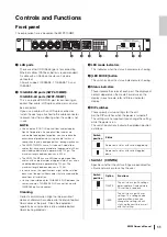
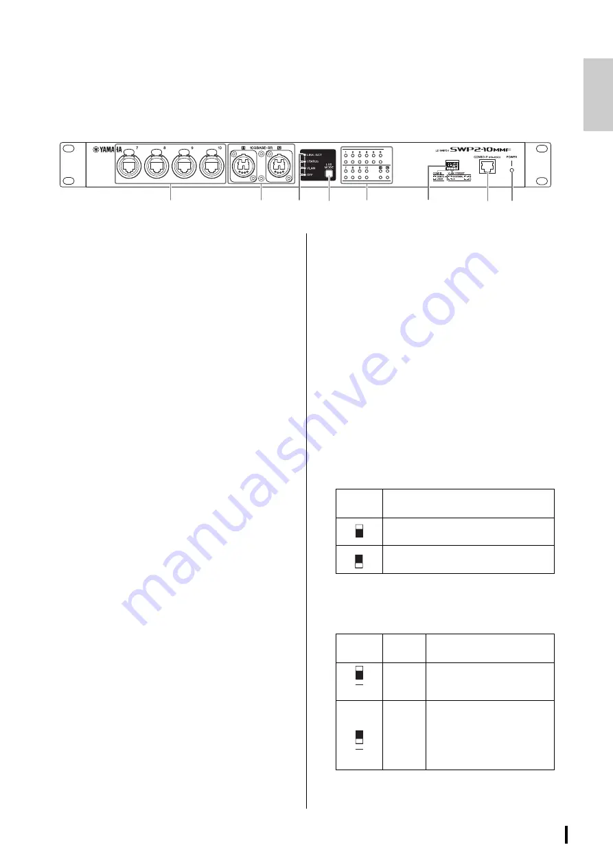
The explanation here is based on the SWP2-10MMF. 

1

LAN ports

These are etherCON (RJ-45) ports for connecting 
Ethernet cables (CAT5e or better is recommended). 
A cable with an RJ-45 connector can also be 
connected.
All ports support 1000BASE-T, 100BASE-TX, and 
10BASE-T.

2

10GBASE-SR ports (SWP2-10MMF)/
10GBASE-LR ports (SWP2-10SMF)

This is an opticalCON DUO port for connecting an 
optical fiber cable. LC Duplex connectors can also 
be connected.
If you use a cable with an LC Duplex connector, 
fasten the dust cap attached to the cable connector 
to prevent dust from adhering when the cable is not 
in use. 

NOTE

• Use an opticalCON DUO optical fiber cable made by 

Neutrik Corporation. Since optical fiber cables are 
vulnerable to being bent or pulled, you can reduce the 
occurrence of problems by using a cable that has a 
strong sheath and is equipped with a locking mechanism.

• The SWP2-10MMF can use GI-type multi-mode fiber 

cables that have a core diameter of approximately 50 μm 
and cladding diameter of approximately 125 μm. The 
maximum length between devices is 300 m.

• The SWP2-10SMF can use SM-type single-mode fiber 

cables with a core diameter of approximately 9 μm and a 
cladding diameter of approximately 125 μm. The 
maximum length between devices is 10 km.

• In some cases, the specifications might not be satisfied 

because of the optical fiber cables that are used and the 
conditions of installation.

• Link up is possible only for 10GBASE-SR/LR between the 

same standards. 10GBASE-SR/LR can not link up with 
1000BASE optical standards.

Cleaning

Correct communication might not be possible if 
debris and/or dust has adhered to the ends of optical 
fiber cables or the ports. Clean the equipment 
regularly by using commercially available optical 
fiber cleaning products.

3

LED mode indicators

This indicates what the status indicators are showing.

4

[LED MODE] button

This switches what the status indicators are showing.

5

Status indicators

These indicate the status of each port. The displayed 
content depends on the mode. For details on the 
display in each mode, refer to “Status indicator 
display.”

6

DIP switches

These specify startup settings for the unit.
Set the DIP switches when the power is turned off. 
The settings are not applied if you change the setting 
while the power is on.
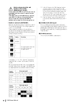
The switch illustrations indicate the up/down position 
as follows.

• Switch 1 (CONFIG)

Specifies whether the unit’s settings are optimized for 
a Dante network or are set by the user.

1

2

3

4

5

6

7

8

Switch 
position

Status

Represent a status with switch toggled up.

Represent a status with switch toggled 
down.

Switch 
position

Option

Functions

DANTE

The unit starts up with settings 
optimized for a Dante network. 
This setting is read only.

USER

The unit starts up with user 
settings. This setting can be 
read or written; when you 
change the setting, the unit 
starts up the next time as well 
with that setting.

1

1

Summary of Contents for SWP2

Page 1: ...Português Italiano Русский 日本語 Owner s Manual Bedienungsanleitung Mode d emploi Manual de instrucciones Manual do Proprietário Manuale di istruzioni Руководство пользователя 取扱説明書 JA RU IT PT ES FR DE EN L2 SWITCH SWP2 10MMF SWP2 10SMF ...

Page 2: ...ture does not operate normally or has been dropped PRÉCAUTIONS CONCERNANT LA SÉCURITÉ 1 Lire ces instructions 2 Conserver ces instructions 3 Tenir compte de tous les avertissements 4 Suivre toutes les instructions 5 Ne pas utiliser ce produit à proximité d eau 6 Nettoyer uniquement avec un chiffon propre et sec 7 Ne pas bloquer les orifices de ventilation Installer l appareil conformément aux inst...

Page 3: ...t occur in all installations If this product is found to be the source of inter ference which can be determined by turning the product OFF and ON please try to eliminate the problem by using one of the following measures Relocate either the product generating the interference or the device that is being affected by the interference Utilize power outlets that are on different branch circuit breaker...

Page 4: ...ssible If some trouble or malfunction occurs immediately disconnect the all plugs from the outlet Remove the electric plug from the outlet when the product is not to be used for extended periods of time Do not touch the product or the electric plug during an electrical storm Be sure to connect to an appropriate outlet with a protective grounding connection Improper grounding can result in electric...

Page 5: ...ring the day in order to prevent the possibility of panel disfiguration unstable operation or damage to the internal components Condensation can occur in the product due to rapid drastic changes in ambient temperature when the product is moved from one location to another or air conditioning is turned on or off for example Using the product while condensation is present can cause damage If there i...

Page 6: ...tion for users on collection and disposal of old equipment This symbol on the products packaging and or accompanying documents means that used electrical and electronic products should not be mixed with general household waste For proper treatment recovery and recycling of old products please take them to applicable collection points in accordance with your national legislation By disposing of the...

Page 7: ... any other party handling or distributing the Software make no warranty neither explicit nor implicit regarding the merchantability or suitability of the Software for any particular purpose 2 Yamaha its subsidiaries their sales representatives and dealers and any other party handling or distributing the Software shall bear no responsibility for any damages including but not limited to lost profit ...

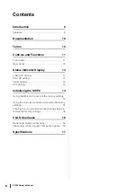
Page 8: ...STATUS setting 14 VLAN setting 14 OFF setting 14 Initializing the SWP2 14 Using the Web GUI to restore the factory settings 14 Using the cold start command to restore the factory settings 15 Entering the I uppercase I key during startup to restore the factory settings 15 VLAN Use Cases 16 Redundant Dante connections 16 Separating control signals from audio signals 16 Specifications 17 ...

Page 9: ...ommended settings such as QoS EEE and IGMP Snooping for stable operation of the Dante network can be specified with only DIP switch The 10GBASE SR LR ports support 10 gigabit allowing operation without fear of insufficient bandwidth even on a Dante network that is set to a sampling frequency of 96 kHz VLAN presets provided Three types of preset VLAN settings are provided allowing a more stable net...

Page 10: ...nk aggregation is a function that bundles multiple LAN SFP ports that connect network devices and treats them as a single logical interface in order to expand the communication bandwidth A group that is bundled using link aggregation is called a link aggregation group LAG Link aggregation is a technology that is useful when multiple communications are occurring The communications can be distribute...

Page 11: ...because of the optical fiber cables that are used and the conditions of installation Link up is possible only for 10GBASE SR LR between the same standards 10GBASE SR LR can not link up with 1000BASE optical standards Cleaning Correct communication might not be possible if debris and or dust has adhered to the ends of optical fiber cables or the ports Clean the equipment regularly by using commerci...

Page 12: ...oad technical reference material HTML 1 In the VLAN presets the IGMP Snooping function is turned on except for VLAN 2 in presets A and B preventing multicast communication such as Dante s multicast flow from being forwarded to unnecessary routes For this reason in the case of A or B you should use the VLAN 1 port for audio signals such as Dante and use the VLAN 2 port for control signals 2 If you ...

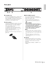
Page 13: ...32 type jack for supplying an external power supply 24V as a backup for the SWP2 s internal power supply Connect a Yamaha PA 700 AC adaptor or an equivalent product recommended by Yamaha CAUTION Before connecting the external power supply you must turn off the external power supply Failing to do so may cause electrocution or malfunctions EXT DC INPUT connector is intended to be supplied by Power S...

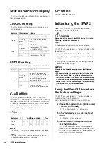
Page 14: ... the factory settings NOTICE When restoring the factory settings note the following points All communication is halted immediately after execution When you execute this the settings will also return to their factory set state If necessary use external memory to save the settings before you proceed with initialization For details on how to export settings to external memory refer to the SWP2 series...

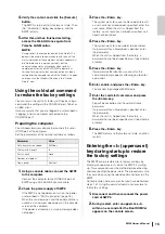
Page 15: ...on a startup message does not appear 3 Press the Enter key The system waits for a user name to be entered If a user name has already been specified enter the user name When the unit is shipped from the factory a user name has not been specified so it need not be entered 4 Press the Enter key The system waits for a password to be entered If a password has already been specified enter the password W...

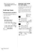
Page 16: ...as for Editor or StageMix from Dante s audio signals making the network more stable This diagram shows a setup using VLAN preset B If VLANs are not used and control signals and audio signals flow across the same network the two will compete for communication bandwidth In order to prevent such an effect we recommend that you use VLANs to separate the control signal and audio signal networks P S P S...

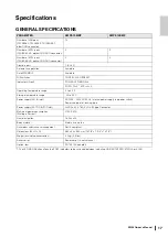
Page 17: ...P switches CONFIG VLAN PRESET Indicators Front POWER LED MODE 4 PORT 10 2 1 SFP 2 2 Operating temperature range 0 to 40 C Storage temperature range 20 to 60 C Power supply AC IN inlet AC100V 240V 50 60 Hz Internal power supply no power switch Power supply inlet locking type Power supply EXT DC INPUT inlet 24VDC 2V 0 78A XLR 4 32 type Connector Maximum power consumption Wattage Current 21W 0 35A He...

Page 18: ...10 km 3 10GBASE SR SWP2 10MMF 10GBASE LR SWP2 10SMF 4 For the pin assignments refer to CONNECTOR PIN ASSIGNMENTS 5 Pin 4 24VDC pin 1 GND pins 2 and 3 N C External power supply requirements 24VDC 2V 0 78A CONNECTOR PIN ASSIGNMENTS CONSOLE RS 232C These signals are not used on the SWP2 Terminal Format Level Connector 1 10 1 IEEE802 3 10BASE T 100BASE TX 1000BASE T etherCON CAT5e 11 12 2 IEEE802 3ae ...

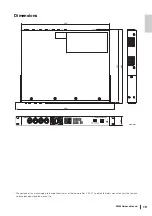
Page 19: ...nual 19 Dimensions The contents of this manual apply to the specifications as of the firmware Rev 2 03 01 To obtain the latest manual access the Yamaha website then download the manual file 480 362 355 430 44 Unit mm ...

Page 20: ......

Page 21: ...6168 SWEDEN FINLAND ICELAND Yamaha Music Europe GmbH Germany filial Scandinavia JA Wettergrensgata 1 400 43 Göteborg Sweden Tel 46 31 89 34 00 DENMARK Yamaha Music Denmark Fillial of Yamaha Music Europe GmbH Tyskland Generatorvej 8C ST TH 2860 Søborg Denmark Tel 45 44 92 49 00 NORWAY Yamaha Music Europe GmbH Germany Norwegian Branch Grini Næringspark 1 1332 Østerås Norway Tel 47 6716 7800 CYPRUS Y...

Page 22: ...Published 03 2019 MWES A0 2019 Yamaha Corporation Manual Development Group VAV9140 Yamaha Downloads http download yamaha com Yamaha Pro Audio global website http www yamahaproaudio com ...

Reviews: