


ENGINE INSPECTION
5-1
EAS2RD1039
ENGINE INSPECTION
EAS20720
MEASURING THE COMPRESSION
PRESSURE
The following procedure applies to checking and
adjusting the compression pressure.
TIP
Insufficient compression pressure will result in a
loss of performance.
1. Measure:
•
Valve clearance
Out of specification
Adjust.
Refer to “ADJUSTING THE VALVE CLEAR-
ANCE” on page 3-5.
2. Start the engine, warm it up for several min-
utes, and then turn it off.
3. Remove:
•
Spark plug cap
4. Remove:
•
Spark plug
NOTICE
ECA20470
Before removing the spark plug, use com-
pressed air to blow away any dirt accumulat-
ed in the spark plug well to prevent it from
falling into the cylinder.
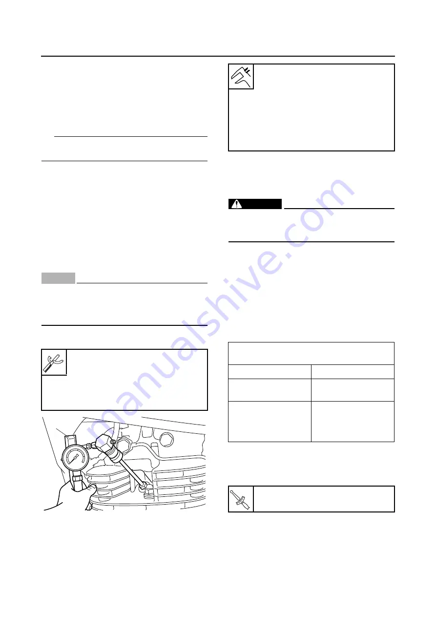
5. Install:
•
Compression gauge “1”
6. Measure:
•
Compression pressure
Out of specification
Refer to steps (b) and
(c).
▼▼▼▼▼▼▼▼▼▼▼▼▼▼▼▼▼▼▼▼▼▼▼▼▼▼▼▼▼▼▼▼
a. With the throttle wide open, kick the kickstart-
er lever until the reading on the compression
gauge stabilizes.
WARNING
EWA2RD1003
To prevent spark generation, spark plug lead
should be grounded before cranking by the
kickstarter.
b. If the compression pressure is above the
maximum specification, check the cylinder
head, valve surfaces, and piston crown for
carbon deposits.
Carbon deposits
Eliminate.
c. If the compression pressure is below the min-
imum specification, pour a teaspoonful en-
gine of oil into the spark plug bore and
measure again.
Refer to the following table.
▲▲▲▲▲▲▲▲▲▲▲▲▲▲▲▲▲▲▲▲▲▲▲▲▲▲▲▲▲▲▲▲
7. Install:
•
Spark plug
8. Connect:
•
Spark plug cap
Compression gauge
90890-03081
Engine compression tester
YU-33223
Extension
90890-04082
1
Standard compression pressure
(at sea level)
1050 kPa/700 r/min (10.5
kgf/cm
2
/700 r/min, 149.3 psi/700
r/min)
Minimum–maximum
910–1180 kPa/700 r/min
(9.1–11.8 kgf/cm
2
/700 r/min,
129.4–167.8 psi/700 r/min)
Compression pressure (with oil applied into
the cylinder)
Reading
Diagnosis
Higher than without
oil
Piston ring(s) wear or
damage
Repair.
Same as without oil
Piston, valves, cylin-
der head gasket or
piston possibly defec-
tive
Repair.
Spark plug
25 Nm (2.5 m·kgf, 18 ft·lbf)
T
R
.
.
Summary of Contents for SR400 2014
Page 1: ...2014 SERVICE MANUAL SR400 SR400E 2RD 28197 E0 ...
Page 2: ......
Page 8: ......
Page 54: ...LUBRICATION SYSTEM CHART AND DIAGRAMS 2 27 1 3 2 ...
Page 56: ...LUBRICATION SYSTEM CHART AND DIAGRAMS 2 29 1 2 3 4 5 8 10 9 a b b a 6 7 ...
Page 58: ...LUBRICATION SYSTEM CHART AND DIAGRAMS 2 31 2 4 c c 3 1 ...
Page 60: ...CABLE ROUTING 2 33 EAS20430 CABLE ROUTING Right side view ...
Page 62: ...CABLE ROUTING 2 35 Left side front view ...
Page 64: ...CABLE ROUTING 2 37 Left side rear view ...
Page 66: ...CABLE ROUTING 2 39 Upper front view ...
Page 68: ...CABLE ROUTING 2 41 Upper rear view ...
Page 70: ...CABLE ROUTING 2 43 Headlight ...
Page 72: ...CABLE ROUTING 2 45 Handle ...
Page 74: ...CABLE ROUTING 2 47 Fuel tank breather hose ...
Page 76: ...CABLE ROUTING 2 49 Fuel pump case ...
Page 78: ...CABLE ROUTING 2 51 Throttle body upper view ...
Page 80: ...CABLE ROUTING 2 53 Throttle body side view ...
Page 82: ...CABLE ROUTING 2 55 Air induction system solenoid ...
Page 84: ...CABLE ROUTING 2 57 ...
Page 113: ...PERIODIC MAINTENANCE 3 27 1 a b ...
Page 114: ...PERIODIC MAINTENANCE 3 28 ...
Page 172: ...CHAIN DRIVE 4 56 ...
Page 234: ...TRANSMISSION 5 60 ...
Page 249: ...THROTTLE BODY 6 14 ...
Page 250: ...AIR INDUCTION SYSTEM 6 15 EAS27040 AIR INDUCTION SYSTEM 1 2 3 4 5 1 2 3 4 5 ...
Page 254: ...AIR INDUCTION SYSTEM 6 19 ...
Page 257: ......
Page 265: ...CHARGING SYSTEM 7 8 3 AC magneto 4 Rectifier regulator 5 Battery 6 Main fuse 36 Frame ground ...
Page 267: ...CHARGING SYSTEM 7 10 ...
Page 277: ...SIGNALING SYSTEM 7 20 ...
Page 303: ...FUEL INJECTION SYSTEM 7 46 ...
Page 307: ...FUEL PUMP SYSTEM 7 50 ...
Page 308: ...ELECTRICAL COMPONENTS 7 51 EAS27973 ELECTRICAL COMPONENTS 11 9 12 13 14 15 1 2 3 4 5 6 7 8 10 ...
Page 310: ...ELECTRICAL COMPONENTS 7 53 14 2 15 1 3 4 5 6 7 8 10 11 13 12 9 ...
Page 336: ...TROUBLESHOOTING 8 5 ...
Page 338: ......
Page 339: ......
Page 340: ......


