background image

SERVICE MANUAL

This manual has been provided for the use of authorized YAMAHA Retailers and their service personnel.
It has been assumed that basic service procedures inherent to the industry, and more specifically YAMAHA Products, are already
known and understood by the users, and have therefore not been restated.

WARNING:

Failure to follow appropriate service and safety procedures when servicing this product  may result in personal
injury, destruction of expensive components, and failure of the  product to perform as specified. For these reasons,
we advise all YAMAHA product owners that any service required should be performed by an authorized YAMAHA
Retailer or the appointed service representative.

IMPORTANT:

The presentation or sale of this manual to any individual or firm does not constitute authorization,  certification  or
recognition  of  any  applicable  technical  capabilities,  or establish a principle-agent relationship of any form.

The data provided is believed to be accurate and applicable to the unit(s) indicated on the cover.  The research, engineering, and service
departments of YAMAHA are continually striving  to improve YAMAHA products. Modifications are, therefore, inevitable and
specifications are subject to change without notice or obligation to retrofit. Should any discrepancy appear to exist, please contact the
distributor's Service Division.

WARNING:

Static discharges can destroy expensive components. Discharge any static electricity your body may have
accumulated by grounding yourself to the ground buss in the unit (heavy gauge black wires connect to this buss).

IMPORTANT:

Turn the unit OFF during disassembly and part replacement. Recheck all work before you apply power to the unit.

IMPORTANT NOTICE

1 0 0 9 3 9

SERVICE MANUAL

RX-V757/DSP-AX757/DSP-AX757SE

RX-V657/HTR-5860

AV RECEIVER/AV AMPLIFIER

DISPLAY DATA  . . . . . . . . . . . . . . . . . . . . . . . . . . 51–52
IC DATA  . . . . . . . . . . . . . . . . . . . . . . . . . . . . . . . . 53–61
PIN CONNECTION DIAGRAM  . . . . . . . . . . . . . . . . . 62
BLOCK DIAGRAM  . . . . . . . . . . . . . . . . . . . . . . . . 63–64
PRINTED CIRCUIT BOARD  . . . . . . . . . . . . . . . . 65–84
SCHEMATIC DIAGRAM  . . . . . . . . . . . . . . . . . . . 85–95
PARTS LIST  . . . . . . . . . . . . . . . . . . . . . . . . . . . . 97–133
REMOTE CONTROL RAV272, RAV273  . . . . 134–135
REMOTE CONTROL RAV252, RAV253  . . . . 136–137

■ 

CONTENTS

TO SERVICE PERSONNEL  . . . . . . . . . . . . . . . . . . 2–3
FRONT PANELS  . . . . . . . . . . . . . . . . . . . . . . . . . . . 3–5
REMOTE CONTROL PANELS  . . . . . . . . . . . . . . . . . . 6
REAR PANELS  . . . . . . . . . . . . . . . . . . . . . . . . . . . 7–12
SPECIFICATIONS / 

参考仕様  . . . . . . . . . . . . . . . . .

13–17

INTERNAL VIEW  . . . . . . . . . . . . . . . . . . . . . . . . . . . . 18
DISASSEMBLY PROCEDURES / 

分解手順  . . . . .

19–27

SELF DIAGNOSIS FUNCTION (DIAG) /

自己診断機能(ダイアグ)

 . . . . . . . . . . . . . . . . . . . . 28–49

AMP ADJUSTMENT / 

アンプ部調整  . . . . . . . . . . . . . . .

50

RX-V757/DSP-AX757/DSP-AX757SE

RX-V657/HTR-5860


  ’05.03

Summary of Contents for RX-V657 - AV Receiver

Page 1: ...rvice departments of YAMAHA are continually striving to improve YAMAHA products Modifications are therefore inevitable and specifications are subject to change without notice or obligation to retrofit Should any discrepancy appear to exist please contact the distributor s Service Division WARNING Static discharges can destroy expensive components Discharge any static electricity your body may have...

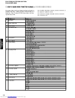
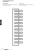
Page 2: ...h 5 Front GAIN 1 6 Front GAIN 2 7 Zone 2 Amp ON 5 XCH INPUT 1 XCH INPUT_6 2 XCH INPUT_8 6 MIC CHECK 1 MIC CHK 7 VFD CHECK 1 VFD CHECK Initial display 初期表示 2 VFD OFF OSD OFF 3 VFD ALL OSD 128 character pattern 4 VFD DIMMER OSD OFF 5 VFD PATTERN OSD OFF 8 MANUAL TEST 1 TEST ALL 2 TEST FRNT L 3 TEST CENTER 4 TEST FRNT R 5 TEST SURR R 6 TEST SB R 7 TEST SB L 8 TEST SURR L 9 TEST PRES L 10 TEST PRES R ...

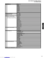
Page 3: ...hese models 2 PS_Hi このモデルには適用されません 3 DC_Lo 4 DC_Hi 5 TEMP 6 PL_8_M_L 7 PL_8_M_H 8 PL_8_N_L 9 PL_8_N_H 10 PL_6_M_L 11 PL_6_M_H 12 PL_6_N_L 13 PL_6_N_H 17 PROTECTION HISTORY 1 history 1 2 history 2 3 history 3 4 history 4 18 SOFT SWITCH 1 SW MODE 2 MODEL SETTING 3 DESTINATION 4 TUNER DESTINATION 5 TUNER TYPE 6 VIDEO FORMAT 7 ZONE2 8 AAC 9 TUNER 10 Z2Amp 11 OSD 12 YPAO 19 SOFTWARE VERSION 1 uCOM Ver ...

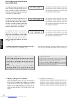
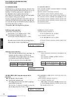
Page 4: ...below and it will be possible to enter the DIAG mode The protection functions other than the excess current detect function will be disabled Press the STANDBY ON key while simultaneously press ing those two keys indicated in the figure above At this time keep pressing those two keys for 3 seconds or longer In this mode the SLEEP segment of the FL display of the main unit flashes to indicate that t...

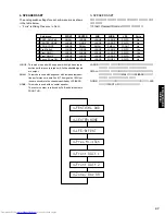
Page 5: ...ープニング プロテクショ ン履歴 バージョン が表示され 数秒後にダイアグメ ニュー表示 1 ANALOG BYPASS となります Display provided when DIAG started When the monitor is connected DIAGNOSTIC MENU appears on its screen as shown in the figure On the FL display of the main unit an opening message including the version and the protection history appears for a few seconds followed by the diagnostic menu dis play 1 ANALOG BYPASS Opening message オープニン...

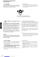
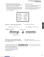
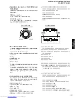
Page 6: ...ower 各プロクテクションの検出に関しては 後述のダイアグメ ニューNo 10 AD DATA 42ページ を参照してください History of protection function When the protection function has worked its history is stored in memory with a backup Even if no abnormality is noted while servicing the unit an abnormality which has occurred previ ously can be defined as long as the backup data has been stored The history of the protection function is cleared when DI...

Page 7: ...STATUS の確認ができます ダイアグ開始時の初期設定 ダイアグ開始時に以下のような設定になります ダイア グ解除時にはダイアグ開始前の状態に戻ります マスターボリューム 20dB インプット DVD マルチチャンネルINPUTオフ エフェクトレベル 0 dB オーディオミュート オフ スピーカーリレーA B オン スピーカー設定 LARGE BASS OUT SWFR ダイアグメニュー BYPASS 1 ANALOG BYPASS Functions in DIAG mode In addition to the DIAG menu items functions as listed below are available Input selection Multi channel input Center Surround Surround Back Sub woofer level...

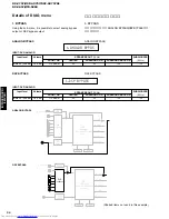
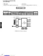
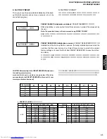
Page 8: ...ER 50 Hz SPEAKERS OUT 1KHz Input level Both ch 20 dBm Volume 6 5 dB SURROUND BACK L R INPUT DVD ANALOG FRONT L R 13 0 dBm CENTER SURROUND L R SUBWOOFER 50 Hz SPEAKERS OUT 1KHz Input level Both ch 20 dBm Volume 6 5 dB SURROUND BACK L R INPUT DVD ANALOG 1 ANALOG BYPAS 1 DSP BYPASS ANALOG BYPASS DSP BYPASS Shaded items not used in this example DIR LC89057 DSP DECODE POST PROCESSING TI DA60Y A D AK462...

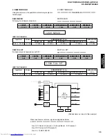
Page 9: ... INPUT DVD ANALOG FRONT L R 13 0 dBm CENTER 13 0 dBm SURROUND L R 13 0 dBm SUBWOOFER 50 Hz 0 5 dBm SPEAKERS OUT 1KHz Input level Both ch 20 dBm Volume 6 5 dB SURROUND BACK L R 13 0 dBm INPUT DVD ANALOG 2 RAM MARGIN 2 RAM FULL BIT Shaded items not used in this example FRONT 15 0 dB CENTER 13 5 dB SURROUND 9 0 dB SUBWOOFER 21 dB SURROUND BACK 7 5 dB PRESENCE 15 0 dB FRONT 0 dB CENTER 0 dB SURROUND 0...

Page 10: ...処理を行います 3 PRO LOGIC Dolby PRO LOGIC is applied to input stereo source 3 PRO LOGIC FRONT L R 13 0 dBm CENTER 13 0 dBm SURROUND L R SUBWOOFER 50 Hz SPEAKERS OUT 1KHz Input level Each ch 20 dBm Both ch 20 dBm Volume 6 5 dB 6 5 dB SURROUND BACK L R INPUT DVD ANALOG DIR LC89057 DSP DECODE POST PROCESSING TI DA60Y A D AK4628 DRAM FL FR PL PR C SW SL SR SBL SBR ROM XMDT U C models ...

Page 11: ...ormance a small unit The signals of 80Hz or less are mixed into the channel specified by LFE BASS NONE This mode is used with no center speaker The center content is reduced by 3dB and distributed to FRONT L R 4 SPEAKERS SET 各サブメニューにおけるアナログスイッチの設定は以下の 通りです F mixはPresenceをFront mixするかどうかです 4 SPEAKERS SET The analog switch settings for each sub menu are as shown in the table below F mix is Mixing Pr...

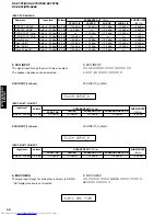
Page 12: ...ONE 3 LFE B FRNT 1kHz 4 LFE B FRNT 50Hz 5 Pres Mix 5ch 6 Front GAIN 1 7 Front GAIN 2 8 Zone 2 Amp ON XCH INPUT 6 ohms XCH INPUT_6 ohms XCH INPUT 8 ohms XCH INPUT_8 ohms FRONT L R 13 0 dBm CENTER 13 0 dBm SURROUND L R 13 0 dBm SUBWOOFER 50 Hz 8 5 dBm SPEAKERS OUT 1KHz Input level Both ch 20 dBm Volume 6 5 dB SURROUND BACK L R 13 0 dBm INPUT MULTI CH INPUT FRONT L R 13 0 dBm CENTER 13 0 dBm SURROUND...

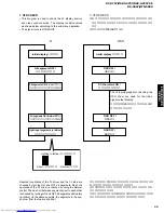
Page 13: ...てFLドライバーの動作 チェックを行います さらに全セグメントを交互 格子状 に点灯 消灯することで 隣り合うセグメントのショートをチェックします Segment conditions of the FL driver and the FL tube are checked by turning ON and OFF all segments Next the operation of the FL driver is checked by using the dimmer control Then a short between segments next to each other is checked by turning ON and OFF all segments alternately in lattice In the above example the segments ...

Page 14: ...ANUAL TEST DSP からサブメニューで指定したチャンネルへ THX 準拠 のテストノイズを出力します 8 MANUAL TEST The test noise based THX is output to the channel specified by the sub menu from the DSP 8 TEST ALL 8 TEST FRNT L 8 TEST CENTER 8 TEST FRNT R 8 TEST SURR R 8 TEST SB R 8 TEST SB L 8 TEST SURR L 8 TEST LFE 8 TEST PRES L 8 TEST PRES R ...

Page 15: ...んで初期化をする前に チュー ナーのユーザーメモリー内容を下表に書き写してください 初期 化をすると ユーザーメモリーの内容は消えてしまいます CAUTION Before setting to the PRESET RESERVED write down the existing preset memory content of the Tuner in a table as shown below This is be cause setting to the PRESET RESERVED will cause ALL user memory contents to be erased Preset group A B C D E P1 P2 P3 P4 P5 P6 P7 P8 PRESET STATIONS プリセット局 STATION FM FACTORY PRESET DATA...

Page 16: ...ーで 表示します オーディオ信号処理は実行前の状態を維持します K0 K1 のメニューにすると 全キーの値を検出するため キー操作はできなくなりますが 本体のVOLUME を回すこ とにより 次のサブメニューに進めることができます こ のとき 2 クリック以上回すと ボリューム値が変化するの で注意してください 図中の数値は参考例です 10 AD DATA CHECK With this sub menu used the key scanning A D value of the voltage at the abnormality detect protection port etc are displayed The A D conversion value is displayed in The state before audio signal processing is kep...

Page 17: ...ODE MULTI CH INPUT 42 53 STRAIGHT FM AM 54 63 TONE CONTROL A B C D E 64 72 PRESET TUNING PRESET TUNING q 73 80 SPEAKERS B PRESET TUNING w 81 88 SPEAKERS A MEMORY 89 95 PURE DIRECT TUNING MODE 96 100 KEY OFF KEY OFF Display K0 K1 0 6 7 13 14 21 22 31 32 41 INPUT MODE MULTI CH INPUT 42 53 STRAIGHT FM AM 54 63 TONE CONTROL A B C D E 64 72 PRESET TUNING PRESET TUNING q 73 80 SPEAKERS B PRESET TUNING w...

Page 18: ...r in the hexadecimal notation During signal processing the status before execution of this menu is maintained Numeric values in the figure example are for reference 4th byte 3rd byte 2nd byte 1st byte 5th byte DST DSP ステータス DST DSP status 12 XMS1xxxxxxx 12 XM2xxxxxxx L 11111100 H 11111000 HIGH BYTE DATA HIGH BYTE DATA 11 V CONV STATUS ビデオコンバージョンIC TA1270 からの受信データを表 示します 図中の数値は参考例です 11 V CONV STATU...

Page 19: ...情報 bit Information bit 7 Digital mute bit 6 bit 5 6 1 7 1 processing bit 4 Analog mute bit 3 bit 2 PCM through bit 1 bit 0 dts analog mute Display Audio code 00 1 1 01 1 0 02 2 0 03 3 0 04 2 1 05 3 1 06 2 2 07 3 2 08 2 3 09 3 3 0A 3 4 0B over 6 1 0C Milti Mono 0D Milti PCE 0E Unknown 0F Undefined Display Fs kHz 00 Analog 01 32kHz 02 44 1kHz 03 48kHz 04 64kHz 05 88 2kHz 06 96kHZ 07 128kHZ 08 176 4k...

Page 20: ...を自己診 断します エラーが検出されなかった場合は NoEr と表示されます 14 DSP BUS CHECK This menu is used to self diagnose whether or not the bus connection for the TI DA60Y and the external ROM RAM is made properly When no error is detected NoEr appears on display TI BUS Boot No error detected 不良検出なし or When this indication is displayed within seconds or displayed alter nately NoEr and Boot it is highly possible that there are ...

Page 21: ...AIGHT key 17 PROTECTION HISTORY 過去のプロテクション履歴を4つまで表示します 17 PROTECTION HISTORY Four protection histories are display 18 SOFT SWITCH 18 SOFT SWITCH P C B 上の機能設定をソフト的に切り替えて 製品を動作さ せる機能です 操作は サブメニューを選んだ後 STRAIGHT キーで切り 替えます プロテクション機能は P C B の設定に従います AC接続で P C B の設定に初期化されます 初期化後の各 機能の表示は P C B 上の設定によります This menu is used to switch the function settings on P C B through the software so as to activate the...

Page 22: ...SW MODE Selectable when MODEL has been selected TUNER DEST INATION J UC R ABG or RL can be se lected SW MODE Selectable when FNC has been se lected TUNER TYPE NRM RDS or XM can be selected SW MODE Selectable when FNC has been selected VIDEO FORMAT NTSC or PAL can be selected SW MODE Selectable when FNC has been selected ZONE2 NOT or EXIST can be selected SW MODE Se lectable when FNC has been selec...

Page 23: ...e numeric value in the diagram is for reference VER I039 CHECK SUM E8F0 O 25 D 34 X A7 PORT 00000000 TI VER 37 TiSUM B97C3D55 EE SUM 0000 Software version of DSP DSP のソフトウェアバージョン Checksum value of DSP DSP のチェックサム Checksum value of EEPROM EEPROM のチェックサム Not applied to these models このモデルには適用されません 20 DSP SOFTWARE REWRITE DSP のソフトウェア書き換えモードです このモデルには適用されません 20 DSP SOFTWARE REWRITE The rewriting mode o...

Page 24: ...NTER R38 FRONT L ch R39 FRONT R ch R37 CENTER R34 SURROUND L ch R35 SURROUND R ch R36 SURROUND BACK R ch R395 SURROUND BACK L ch R47 SURROUND L ch R48 SURROUND R ch R49 SURROUND BACK R ch R398 SURROUND BACK L ch Cut off カット Position for Adjusting MAIN 1 P C B 1 Immediately after the power is turned on measure the voltage across resistor terminals in the column A in the table below and confirm that...

Page 25: ...X V657 HTR 5860 RX V757 DSP AX757 DSP AX757SE RX V657 HTR 5860 DISPLAY DATA V801 17 BT 24GNK WE289300 GRID ASSIGNMENT PIN CONNECTION PATTERN AREA q 9 Note 1 F1 F2 Filament 2 NP No Pin 3 NX No Extend Pin 4 P1 P37 Datum Line 5 1G 17G Grid ...

Page 26: ...52 RX V757 DSP AX757 DSP AX757SE RX V657 HTR 5860 RX V757 DSP AX757 DSP AX757SE RX V657 HTR 5860 ANODE CONNECTION SEGMENT DESIGNATION ...

Page 27: ...4 5 6 7 8 9 10 11 12 RXOUT RX0 RX1 RX2 RX3 DGND DVDD RX4 RX5 VI RX6 UI DVDD DGND 37 38 39 40 41 42 43 44 45 46 47 48 24 23 22 21 20 19 18 17 16 15 14 13 SDIN SLRCK SBCK RDATA RLRCK DVDD DGND RBCK RMCK AGND AVDD LPF DO DI CE CL XMODE DGND DVDD TMCK PIO0 TBCK PIO1 TLRCK PIO2 TDATA PIO3 TXO PIOE LC89057W VF4D E Pull down resistor internal 1 RXOUT 2 RX0 3 RX1 4 RX2 5 RX3 8 RX4 9 RX5 VI 10 RX6 UI 13 LP...

Page 28: ...s 64fs 128fs S LR clock output pin fs s fs 2fs Serial audio data input pin Digital GND Digital power supply Oscillation amplifier output pin Crystal resonator connection output pin Crystal resonator connection external supply clock input pin 24 576 MHz or 12 288 MHz Digital power supply Digital GND Emphasis information U data output Chip address setting pin Non PCM output V flag output Chip addres...

Page 29: ... using register Unconnected 7 GP0 7 EXT_INT7 IOZ General purpose I O0 port 7 Interrupt input polarity selectable individually by using register Unconnected 8 CLKS1 I McBSP1 external clock source 9 DVDD S 3 3V power supply 10 VSS GND Ground 11 CVDD S 1 2V power supply 12 TINP1 AHCLKX0 I IOZ Timer 1 Input McASP0 Transmission MCLK 13 AXR1 11 IOZ McASP1 Transmission reception data 11 14 CVDD S 1 2V po...

Page 30: ...pply 68 EA5 O Z For external memory Address 5 69 EA6 O Z For external memory Address 6 70 EA7 O Z For external memory Address 7 71 EA8 O Z For external memory Address 8 72 DVDD S 3 3V power supply 73 VSS GND Ground 74 EA9 O Z For external memory Address 9 75 SDRAS O Z SDRAM RAS 76 EA10 O Z For external memory Address 10 77 ECLKOUT O Z Clock output for EMIF 78 ECLKIN I Clock input for EMIF Unconnec...

Page 31: ...4 CVDD S 1 2V power supply 125 VSS GND Ground 126 DVDD S 3 3V power supply 127 ED4 IOZ For external memory Data 4 128 ED5 IOZ For external memory Data 5 129 ED3 IOZ For external memory Data 3 130 ED2 IOZ For external memory Data 2 131 ED1 IOZ For external memory Data 1 132 ED0 IOZ For external memory Data 0 133 CVDD S 1 2V power supply 134 VSS GND Ground 135 GP0 1 IOZ General purpose I O0 port 1 U...

Page 32: ...SCIN I X tal input Oscillation 12 to 25MHz 179 OSCOUT O X tal output Unconnected 180 OSCVSS GND X tal GND internal connection Unconnected 181 OSCVDD S X tal 1 2V power supply internal connection Unconnected 182 VSS GND Ground 183 DVDD S 3 3V power supply 184 CLKOUT3 O Programmable clock output up to 32 division of PLL Unconnected 185 EMU1 IOZ JTAG emulation pin 1 1 k ohms PD when boundary scanning...

Page 33: ...D LMIT TRIG SDM SDD SCK BYTE CNVss MUTETI TIBUSY RESET Xout Vss Xin Vcc NMI INTTI INTDIR VSY CSDIR CSTI CSDAC ICDIR ICTI SPIRDY CEEEP CKZ2 DRXM DTXM DTEV TXDF XMPWR RXDF CKEV CLKF BSY Name 81 82 83 84 85 86 87 88 89 90 91 92 93 94 95 96 97 98 99 100 1 2 3 4 5 6 7 8 9 10 11 12 13 14 15 16 17 18 19 20 21 22 23 24 25 26 27 28 29 30 80 79 78 77 76 75 74 73 72 71 70 69 68 67 66 65 64 63 62 61 60 59 58 ...

Page 34: ...EO Conversion DATA VIDEO Conversion Clock HEAD PHONE Detect HEAD PHONE Mute Output MUTE Center MUTE SW For Flash Writing LO Zone 2 MUTE MUTE Front Surround Pre OUT Electronic Volum IC Enable Electronic Volume Reset For Flash Writing HI Selector IC Enable Selector IC Clock Selector IC DATA INPUT Selector BD3841 Clock Model Discriminate 3 BD3841 DATA Component Signal Detector DVD Component Signal De...

Page 35: ... 0 2 0 3 0 8 0 9 1 3 1 4 1 8 1 8 2 2 2 3 2 7 2 8 3 3 3 4 3 8 3 9 4 3 4 4 4 7 4 8 5 0 A D 5V 256 0 13 14 40 41 68 69 92 93 115 116 140 141 170 171 198 199 221 222 244 245 255 DEST 97pin J U C R T K A B GE L Pin Function Name RX V757 DSP AX757 DSP AX757SE RX V657 HTR 5860 100 P97 MOD0 0 1 56 P36 MOD1 55 P37 MOD2 0 0 0 50 P44 MOD3 0 1 1 Ohm 0 0 k 1 0 k 1 0 k 1 5 k 2 2 k 3 3 k 4 7 k 4 7 k 6 8 k 10 0 k...

Page 36: ...VR ZONE2 TUNER ZONE2 RX V757 U C A G RX V657 U C A B G E models TUNER DSP AX757SE model MULTI CH INPUT REC OUT 11 20 10 21 12 19 6 25 9 22 Switch NJU7312AM IC303 2 3 7 8 24 23 Switch NJU7312AM IC303 3 3 3 28 4 27 2 29 DASBL DASBR ADL ADR Switch NJU7312AM IC303 1 3 Z2L Z2R 11 20 8 23 3 28 5 26 10 21 7 24 2 29 5 26 3 4 12 9 22 6 25 19 5 8 9 6 7 IN1 IN2 IN3 IN6 IN7 IN4 IN5 Center Front Surr Surr Back...

Page 37: ... D410 C118 C116 C119 C117 B G B C132 C133 BL G BL 30V Q120 VP D312 12V IC302 12V IC303 12 G 12 C365 C366 9V IC712 9V 5V IC713 5V 5V IC304 5D 3 3V IC306 3 3D G 5V IC714 5V C367 C368 FL1 FL2 Power Detector Reset Q402 403 Q401 POWER RELAY 5 5V IC452 Q501 G 5S 5M 5BU D453 T401 D452 D451 POWER SAVE RY401 s10 D21 C33 3 3V IC21 5BUS 5V IC22 5X 5V IC27 3 3X G XMPWR PURE RY126 4ohms RY126 Input Selector 74...

Page 38: ... 0 6 0 4 8 0 1 0 6 0 6 0 1 0 2 0 2 0 2 0 0 0 3 5 3 5 3 4 3 5 0 1 0 3 5 1 6 1 7 1 8 3 5 0 0 1 0 1 0 1 0 1 0 1 3 5 3 5 4 9 0 3 5 3 4 0 2 0 5 3 1 3 5 0 1 8 0 1 0 3 5 1 8 0 1 1 3 0 3 4 3 4 1 8 0 3 4 1 3 0 0 1 1 3 1 3 0 3 5 3 5 3 5 1 3 0 3 4 3 5 3 5 3 5 3 4 0 0 1 3 3 4 3 4 0 0 3 4 1 3 0 1 3 0 1 3 5 0 3 4 0 3 4 0 0 1 3 1 3 0 3 4 3 4 3 4 0 1 3 0 4 0 4 3 1 3 4 0 1 3 3 1 2 9 2 6 3 4 0 3 4 0 1 8 3 4 1 3 0 3...

Page 39: ...SE RX V657 Page 88 F 8 HTR 5860 Page 89 F 8 TO OPERATION 4 W807 TO OPERATION 5 W807 IC15 AK4382AVT D A Convertter DE EMPHASIS CONTROL 8X INTERPOLATOR MODULATOR SCF SCF CLOCK DIVIDER 8X INTERPOLATOR MODULATOR AUDIO DATA INTERFACE µP INTERFACE 12 15 16 13 14 6 7 8 4 2 3 5 1 11 10 9 CSN VDD VSS DZFL DZFR AOUTL AOUTL AOUTR AOUTR CCLK CDTI PDN MCLK LRCK BICK SDTI IC16 AK4628VQ 192kHz 24bit 8ch CODEC 1 ...

Page 40: ...68MD TE2 Dual OP Amp OUT1 IN1 VCC VCC OUT2 1 2 3 4 5 IN1 IN2 IN2 6 7 8 IC314 NJM4556AL Dual OP Amp IN 1 2 IN 1 3 V CC 4 IN 2 5 IN 2 6 OUT 2 7 V CC 8 OUT 1 1 IC304 NJU7313AM Analog Function Switch 13 NC 18 NC 2 3 4 5 6 7 8 9 10 11 12 14 30 1 29 28 27 26 25 24 23 22 21 20 19 17 15 CONTROL LEVEL SHIFTER LATCH LEVEL SHIFTER LATCH L1 L2 L3 L4 L COM1 L5 L6 L COM2 L7 L8 L COM3 ST VDD VEE R1 R2 R3 R4 R CO...

Page 41: ...UNCTION 1 CB306 Page 87 G 1 All voltages are measured with a 10MΩ V DC electronic volt meter Components having special characteristics are marked Z and must be replaced with parts having specifications equal to those originally installed Schematic diagram is subject to change without notice 電圧は 内部抵抗10MΩの電圧計で測定したものです Z印のある部品は 安全性確保部品を示しています 部品の交換が必要な場合 パーツリストに記載されている部品を使用してください 本回路図は 標準回路図です 改良のため予...

Page 42: ...h a 10MΩ V DC electronic volt meter Components having special characteristics are marked Z and must be replaced with parts having specifications equal to those originally installed Schematic diagram is subject to change without notice 電圧は 内部抵抗10MΩの電圧計で測定したものです Z印のある部品は 安全性確保部品を示しています 部品の交換が必要な場合 パーツリストに記載されている部品を使用してください 本回路図は 標準回路図です 改良のため予告なく変更することがございます IC901 µPC4570G2 Dual OP Amp OUT1 IN1 VCC ...

Page 43: ... 12 0 0 37 2 37 2 37 2 10 5 37 2 37 2 37 2 37 2 10 7 37 2 8 2 37 2 10 5 0 0 10 5 0 4 8 37 2 0 0 10 5 4 8 4 8 8 2 4 2 4 8 10 7 4 2 4 8 29 7 29 7 0 29 0 37 1 0 0 0 0 38 1 37 2 37 2 37 2 0 0 37 2 0 56 2 56 2 AC 57 2 0 AC 82 5 5 1 0 29 1 10 0 4 9 5 0 2 1 0 0 4 9 0 4 9 4 9 4 8 12 0 0 0 R210 D5SB20 Page 91 E 9 TO POWER 1 CB353 Page 91 D 9 TO POWER 1 CB359 Page 91 D 9 TO POWER 1 CB352 Page 91 I 3 TO POWE...

Page 44: ...MER Page 90 F 7 TO MAIN 1 W8 Page 94 F 9 TO CONVERSION 1 CB706 Page 90 D 10 TO MAIN 1 W12 POWER 2 POWER 1 Page 90 A 5 TO MAIN 1 CB6 Page 90 A 4 TO MAIN 1 CB5 Page 90 A 1 TO MAIN 1 W15 Page 87 I 2 TO FUNCTION 1 CB307 Page 87 I 2 TO FUNCTION 1 CB308 Page 87 I 3 TO FUNCTION 1 W301 All voltages are measured with a 10MΩ V DC electronic volt meter Components having special characteristics are marked Z a...

Page 45: ...ION SOFT DECISION SYNC EC CONTROLLER SYNC DETECT 1 DATA DECODER CLOCK RECOVERY 1187 5Hz MEMORY CONTROL OSC DIVIDER VREF CLK 4 332MHz SYNC DETECT 2 VDDA VSSD VDDD RDS ID SYNC SYR VSSA MPX IN DO CL DI CE T1 T2 T3 T4 T5 T6 T7 X IN VREF FL OUT C IN X OUT 3 14 15 19 18 24 1 5 6 4 2 20 21 22 23 7 8 9 10 11 16 17 13 12 IC601 602 MM74HC4051SJX Analog Multiplexers Demultiplexers LEVEL CONVERTER BINARY TO 1...

Page 46: ...5Ω Video Driver 6dB DR 6dB DR 6dB DR 1 2 3 4 5 6 7 8 36 35 34 33 32 31 30 29 VIN1 NFB1 MUTE1 VIN2 NFB2 VCC1 VIN3 NFB3 N C N C VCC1 VOUT1 GND VOUT2 DR CTL2 VOUT3 MUTE4 VCC4 N C N C 6dB DR 6dB DR 6dB DR 11 12 13 14 15 16 17 18 26 25 24 23 22 21 20 19 VIN4 NFB4 MUTE2 VIN5 NFB5 VCC2 VIN6 NFB6 VCC2 VOUT4 GND VOUT5 DR CTL1 VOUT6 MUTE3 VCC3 28 27 9 10 Point r Pin 3 of IC606 IC601 602 MM74HC4051SJX Analog...

Page 47: ...ET PLL DET CLOCK CLOCK IN VSS VIN1 VDD VIN2 Clamp Pulse Ins AGC Det LPF AGC Clamp Ave Bias Det 1 225 IC833 NJM2068MD TE2 Dual OP Amp OUT1 IN1 VCC VCC OUT2 1 2 3 4 5 IN1 IN2 IN2 6 7 8 IC831 832 BD3841FS Function Switch F SW1 F SW1 INPUT FUNCTION 1 F SW2 INPUT FUNCTION 2 32 31 30 29 28 27 26 25 24 23 22 21 20 19 18 17 1 2 3 4 5 6 7 8 9 10 11 12 13 14 15 16 DGND F SW2 CL DA VEE GND VCC RECA1 RECA2 RE...

Page 48: ...5 4 3 1 2 RX V757 RXV657 models TO SUBTRANS 2 CB454 RX V757 DSP AX757 DSP AX757SE RX V657 Page 93 H 7 Page 92 G 7 HTR 5860 Page 94 K 5 TO CONVERSION 2 W831 TO POWER TRANSFORMER no_use 0 01 50 10 16 0 1 16 47 16 47 16 47 16 1 BLM21P600SG 10K 10K 3 3K 3 3K NE5532DR NE5532DR 10 16 10 16 47K 47K 1K 1K 3300P 50 3300P 50 0 1 16 0 1 16 47 16 47 16 1 1 SMUTE CSN MCLK ACKS CCLK DIF0 CDTI DZFL VDD VSS AOUTL...

Reviews: