Patching
Patching the output ports
131
RIVAGE PM10 Operation Manual
Patching the output ports
1.
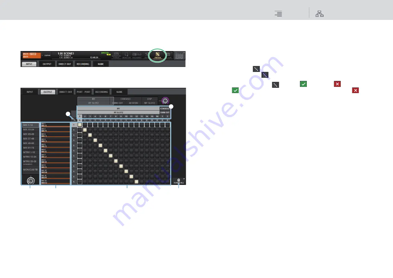
Press the PATCH button on the menu bar to access the PATCH screen.
2.
Press the OUTPUT tab to access the OUTPUT patch window.
The window contains the following items.
1
Channel list (Output channels)
Indicates the output channel numbers as patching destinations.
2
Channel display
Indicates the channels that will be assigned to the output port.
3
Grid
This grid lets you patch output ports (horizontal lines) to output channels (vertical columns).
Currently-patched grids are indicated by white squares. Press or click a desired grid to set or
disable the patch.
4
OUTPUT COMPONENT/SLOT/CH
This section indicates the type of the output component, slot number, and channel number for
the output port.
The abbreviations displayed in this section have the following meaning.
•
M1–M8
..........................I/O rack 1–8
•
CONSOLE
....................Control surface
•
DSP
................................DSP engine
5
Continuous patch
button
Press the continuous patch
button, and then rotate the select knob to in the upper right to
patch the intersecting channels continuously.
If you press the continuous patch
button, the
button and the
button will appear.
Press the
button again to confirm the selected continuous patches. Press the
button
to revert the continuous patches to the previous state.
6
CLEAR ALL button
Press this button to clear all selections.
3.
Use the knob in the upper right to display the desired output ports.
4.
Use the knob in the lower-left corner to display the output channels.
5.
Press the desired grid cell to patch a desired channel.
NOTE
On the RPio622 or RPio222, the output to HY slot 2 can be patched if the routing mode is set to
Mode 2. (See
.) However, the routing mode setting is not included in scene data. Therefore,
if you recall a scene, you must switch to Mode 2.
1
3
6
2
4
5


