2-7
Chapter
2
CONNECTION
5. Connecting to the CC-Link system
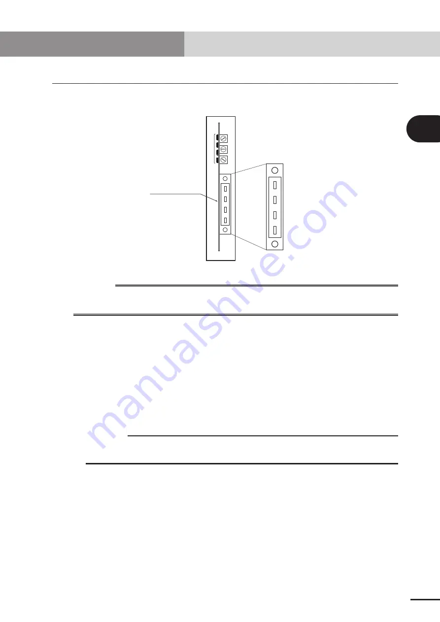
The CC-Link system cable must be connected to the CC-Link compatible module in order
to connect to the CC-Link system.
DA
DB
DG
SLD
1
2
3
4
5
6
7
8
9
1
2
3
4
5
6
7
8
9
1
2
3
4
5
6
7
8
9
Front of the unit
Cable terminal
w
WARNING
WHEN SETTING THE STATION NO., COMPLETELY SHUT OFF THE POWER SUPPLIED TO
THE ROBOT CONTROLLER.
5.1 Connecting to the cable terminal to the controller
Connect the CC-Link system cable to the CC-Link system cable terminal on the CC-Link
compatible module.
[Procedure]
1. Using a phillips head screwdriver, completely loosen the two screws on both sides
of the CC-Link system cable terminal, and remove the terminal block section from
the CC-Link compatible module.
c
CAUTION
Always remove the terminal block section when installing the CC-Link system
cable.
2. Using a phillips head screwdriver, securely fix the CC-Link system cable to the
terminal block removed in step 1. The name of each terminal on the cable terminal
block is shown above.
* When connecting a terminator, connect it across DA-DB.
* A slit to prevent incorrect inverted insertion is provided on the cable terminal
block.
5. Connecting to the CC-Link system
Summary of Contents for RCX series
Page 1: ...User s Manual ENGLISH E E78 Ver 1 08 CC Link YAMAHA NETWORK BOARD RCX series ...
Page 2: ......
Page 12: ......
Page 22: ......
Page 34: ...2 12 MEMO ...
Page 36: ......
Page 50: ......
Page 60: ......
Page 81: ...Chapter 6 APPENDIX Contents 1 Term definition 6 1 ...
Page 82: ......


