ENGINE
3-11
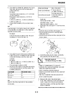
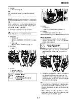
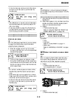
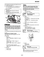
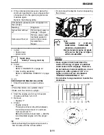
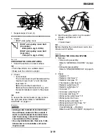
d. If the compression pressure is below the
minimum specification, pour a teaspoonful
of engine oil into the spark plug bore and
measure again.
Refer to the following table.
▲▲▲▲▲▲▲▲▲▲▲▲▲▲▲▲▲▲▲▲▲▲▲▲▲▲▲▲▲▲
7. Install:
• Spark plugs
• Ignition coils
8. Install:
• Radiator
Refer to “RADIATOR” on page 6-1.
• Side cowling assembly
Refer to “GENERAL CHASSIS” on page
4-1.
EAS20730
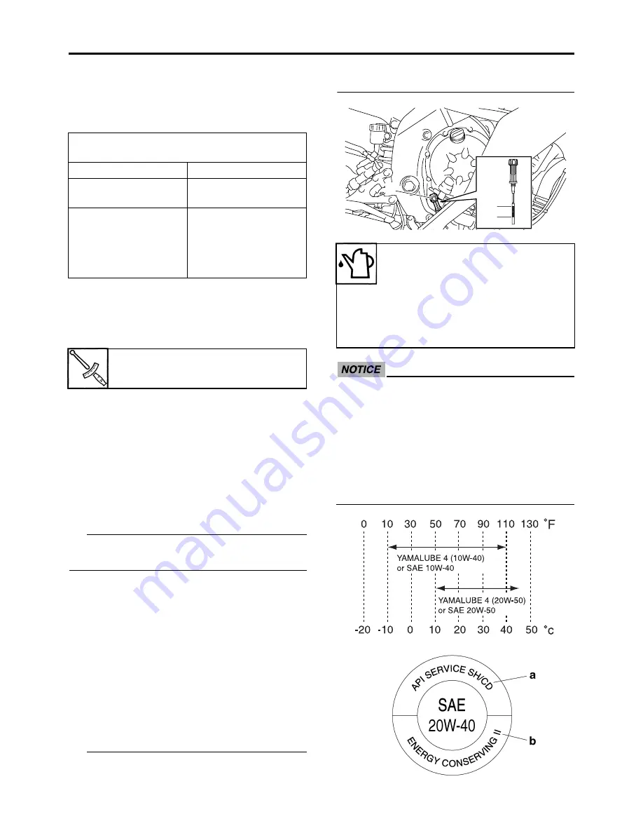
CHECKING THE ENGINE OIL LEVEL
1. Stand the vehicle on a level surface.
TIP
• Place the vehicle on a suitable stand.
• Make sure the vehicle is upright.
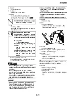
2. Start the engine, warm it up for several
minutes, and then turn it off.
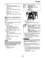
3. Remove:
• Dipstick “1”
4. Check:
• Engine oil level
The engine oil level should be between
the minimum level mark “a” and maxi-
mum level mark “b”.
Below the minimum level mark
→
Add the
recommended engine oil to the proper
level.
TIP
• Before checking the engine oil level, wait a
few minutes until the oil has settled.
• Do not screw the dipstick in when inspecting
the oil level.
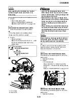
EC2C01005
• Since engine oil also lubricates the
clutch, the wrong oil types or additives
could cause clutch slippage. Therefore,
do not add any chemical additives, or use
engine oils with a grade of CD “a” or
higher, and do not use oils labeled
“ENERGY CONSERVING II” “b”.
• Do not allow foreign materials to enter the
crankcase.
Compression pressure (with oil applied into
the cylinder)
Reading
Diagnosis
Higher than without
oil
Piston ring(s) wear or
damage
→
Repair.
Same as without oil
Pistons, valves, cylin-
der head gasket or
piston ring(s) possi-
bly defective
→
Repair.
Spark plug
13 Nm (1.3 m·kg, 9.6 ft·lb)
Type
YAMALUBE 4 (10W-40),
SAE10W-40, YAMALUBE 4
(20W-50) or SAE20W-50
Recommended engine oil grade
API service SG type or higher,
JASO standard MA
1
a
b
Summary of Contents for R6 2009
Page 1: ...SERVICE MANUAL YZFR6Y C 13S 28197 11 LIT 11616 22 51 2009 ...
Page 6: ......
Page 8: ......
Page 60: ...LUBRICATION SYSTEM CHART AND DIAGRAMS 2 29 EAS20410 LUBRICATION DIAGRAMS 1 2 3 4 ...
Page 62: ...LUBRICATION SYSTEM CHART AND DIAGRAMS 2 31 1 2 3 4 8 7 6 5 ...
Page 64: ...LUBRICATION SYSTEM CHART AND DIAGRAMS 2 33 1 2 3 4 5 ...
Page 66: ...LUBRICATION SYSTEM CHART AND DIAGRAMS 2 35 1 5 4 3 2 ...
Page 68: ...LUBRICATION SYSTEM CHART AND DIAGRAMS 2 37 3 1 2 5 4 ...
Page 70: ...LUBRICATION SYSTEM CHART AND DIAGRAMS 2 39 1 3 2 ...
Page 71: ...LUBRICATION SYSTEM CHART AND DIAGRAMS 2 40 1 Oil pipe 2 Main axle 3 Drive axle ...
Page 72: ...COOLING SYSTEM DIAGRAMS 2 41 EAS20420 COOLING SYSTEM DIAGRAMS 1 2 3 4 ...
Page 74: ...COOLING SYSTEM DIAGRAMS 2 43 A A 2 1 3 4 5 6 7 8 6 13 8 9 15 14 9 10 11 12 ...
Page 76: ...CABLE ROUTING 2 45 EAS20430 CABLE ROUTING ...
Page 78: ...CABLE ROUTING 2 47 ...
Page 80: ...CABLE ROUTING 2 49 ...
Page 82: ...CABLE ROUTING 2 51 ...
Page 84: ...CABLE ROUTING 2 53 ...
Page 86: ...CABLE ROUTING 2 55 ...
Page 88: ...CABLE ROUTING 2 57 ...
Page 90: ...CABLE ROUTING 2 59 A A ...
Page 92: ...CABLE ROUTING 2 61 ...
Page 95: ......
Page 135: ......
Page 206: ...CHAIN DRIVE 4 71 1 2 3 a a New ...
Page 209: ......
Page 240: ...PICKUP ROTOR 5 31 ...
Page 286: ...TRANSMISSION 5 77 ...
Page 300: ...WATER PUMP 6 13 ...
Page 316: ...AIR INDUCTION SYSTEM 7 15 EAS27040 AIR INDUCTION SYSTEM 2 1 2 4 3 4 3 6 4 5 A A ...
Page 323: ......
Page 324: ...IGNITION SYSTEM 8 1 EAS27090 IGNITION SYSTEM EAS27110 CIRCUIT DIAGRAM ...
Page 330: ...ELECTRIC STARTING SYSTEM 8 7 EAS27160 ELECTRIC STARTING SYSTEM EAS27170 CIRCUIT DIAGRAM ...
Page 336: ...CHARGING SYSTEM 8 13 EAS27200 CHARGING SYSTEM EAS27210 CIRCUIT DIAGRAM ...
Page 339: ...CHARGING SYSTEM 8 16 ...
Page 340: ...LIGHTING SYSTEM 8 17 EAS27240 LIGHTING SYSTEM EAS27250 CIRCUIT DIAGRAM ...
Page 344: ...SIGNALING SYSTEM 8 21 EAS27270 SIGNALING SYSTEM EAS27280 CIRCUIT DIAGRAM ...
Page 351: ...SIGNALING SYSTEM 8 28 ...
Page 352: ...COOLING SYSTEM 8 29 EAS27300 COOLING SYSTEM EAS27310 CIRCUIT DIAGRAM ...
Page 355: ...COOLING SYSTEM 8 32 ...
Page 356: ...FUEL INJECTION SYSTEM 8 33 EAS27330 FUEL INJECTION SYSTEM EAS27340 CIRCUIT DIAGRAM ...
Page 395: ...FUEL INJECTION SYSTEM 8 72 ...
Page 396: ...FUEL PUMP SYSTEM 8 73 EAS27550 FUEL PUMP SYSTEM EAS27560 CIRCUIT DIAGRAM ...
Page 399: ...FUEL PUMP SYSTEM 8 76 ...
Page 400: ...ELECTRICAL COMPONENTS 8 77 EAS27970 ELECTRICAL COMPONENTS ...
Page 402: ...ELECTRICAL COMPONENTS 8 79 1 5 4 3 2 6 7 8 9 10 12 13 11 14 15 16 17 18 ...
Page 404: ...ELECTRICAL COMPONENTS 8 81 EAS27980 CHECKING THE SWITCHES ...
Page 431: ......
Page 432: ...YAMAHA MOTOR CO LTD 2500 SHINGAI IWATA SHIZUOKA JAPAN ...

