background image

SCENE function

178

PM5D/PM5D-RH V2 / DSP5D Owner’s Manual    

Reference section

B

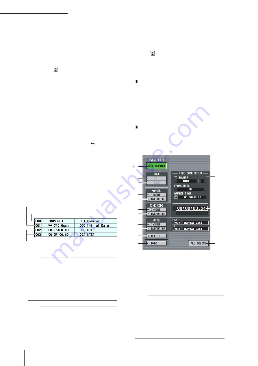
Event list

In this list you can register the scenes to be recalled, 
and the conditions under which the scenes will be 
recalled. Click a line to select the event of that line for 
editing; it will be highlighted in the center of the list.

• No.

Indicates the event number.

• EVENT TRIGGER

This column specifies the condition that will recall each 
event. Click the   button, and in the window that 
appears, use the following three buttons to select the 
condition.

MANUAL

  . . . . . The event can be recalled by the 

DIRECT button in the EVENT 
RECALL area (

3

) or by a User 

Defined key. The EVENT TRIG-
GER field will indicate 
“[MANUAL]”.

INTERVAL

  . . . . The scene will be recalled when a 

specified time has elapsed after the 
preceding scene was recalled. If you 
select this button, specify the wait 
time in the lower part of the win-
dow. The EVENT TRIGGER field 
in the list shows a “ 

” symbol and 

the wait time.

TIME CODE

 . . . The scene will be recalled when the 

time code (LTC, MTC, internal 
time code) reaches the specified 
time. If you select this button, spec-
ify the time code location (hours/
minutes/seconds/frames) in the 
lower part of the window. The 
EVENT TRIGGER field in the list 
shows the time code.

Hint

• As long as an event for which MANUAL is specified is 

selected in the list, the scene will not change until you manu-
ally execute a recall.

• However, if a event for which TIME CODE is specified is 

registered later in the list, events set to MANUAL will be 
skipped when that time code arrives, and the corresponding 
scene will be recalled.

• The condition for recalling the scene that will be recalled 

next is shown in the NEXT SCENE/NEXT EVENT fields in 
the upper part of the display.

Note

• If time code source is OFF, events whose EVENT TRIG-

GER is set to TIME CODE will not be recalled unless you 
perform a manual recall.

• In contrast, events whose EVENT TRIGGER is set to 

INTERVAL will be recalled automatically after the specified 
interval elapses from the previous recall operation, even if 
the time code source is OFF.

• In the two-second interval after time code starts, events may 

not be executed because synchronization is being estab-
lished. You must start time code at least two seconds earlier 
than an event you want to execute.

• SCENE TITLE

This is the number and title of the scene to be recalled. 
Click the   button, and in the window that appears, 
click the number of a scene to select it.

C

EVENT RECALL

Here you can recall events. The following three but-
tons are provided.

 PREV

When you click this button, the event of the line pre-
ceding the last-recalled event will be recalled and 
selected.

• DIRECT

When you click this button, the event currently 
selected in the event list will be recalled. This is used 
mainly to recall an event whose EVENT TRIGGER 
field is set to “[MANUAL]”.

 NEXT

When you click this button, the event of the line fol-
lowing the last-recalled event will be recalled and 
selected.

D

AUTO CAPTURE

This button lets you automatically register events in 
realtime while time code runs. If time code is running 
and this button is on, using the buttons of the panel 
SCENE MEMORY to recall a scene will cause the cor-
responding scene number and time code location to be 
captured, and this will be added as a new event.

Note

• If the list contains previously-recorded events, they will be 

sorted in descending order of their time code.

• If an event already exists at the identical time code location, 

it will be overwritten by the new event.

• Even if time code source is “OFF,” performing a recall oper-

ation while this button is on will register a new event in the 
list. In this case, the EVENT TRIGGER field will be regis-
tered as “[MANUAL]”.

• If an offset value is specified, the sum of the offset value and 

the displayed time code is captured as the time code.

Event that will be recalled manually

Event that will be recalled when time code reaches the 
specified location

Event that will be recalled when the specified interval elapses 
after the previous recall operation

4

9

J

Q

5
6

7
8

K
L

M
N

O

P

Summary of Contents for PM5D

Page 1: ...EN PM5D PM5D RH V2 DSP5D Owner s Manual Owner s Manual ...

Page 2: ...USER SERVICEABLE PARTS INSIDE REFER SERVICING TO QUALIFIED SERVICE PERSONNEL CAUTION RISK OF ELECTRIC SHOCK DO NOT OPEN WARNING TO REDUCE THE RISK OF FIRE OR ELECTRIC SHOCK DO NOT EXPOSE THIS APPARATUS TO RAIN OR MOISTURE 1 IMPORTANT NOTICE DO NOT MODIFY THIS UNIT This product when installed as indicated in the instructions con tained in this manual meets FCC requirements Modifications not express...

Page 3: ...um battery for memory back up Raadpleeg uw leverancier over de verwijdering van de batterij op het moment dat u het apparaat ann het einde van de levensduur of gelieve dan contact op te nemen met de vertegenwoordiging van Yamaha in uw land For the removal of the battery at the moment of the disposal at the end of life please consult your retailer or Yamaha representative office in your country Goo...

Page 4: ...ctric plug from the outlet and have the device inspected by qualified Yamaha service personnel CAUTION Always follow the basic precautions listed below to avoid the possibility of physical injury to you or others or damage to the device or other property These precautions include but are not limited to the following Remove the electric plug from the outlet when the device is not to be used for ext...

Page 5: ...t apply oil grease or contact cleaner to the faders Doing so may cause problems with electrical contact or fader motion Do not use the headphones for a long period of time at a high or uncomfortable volume level since this can cause permanent hearing loss If you experience any hearing loss or ringing in the ears consult a physician Do not rest your weight on the device or place heavy objects on it...

Page 6: ...0 Switching the target of panel operations when cascade connected with the DSP5D 40 5 Input channel operations 41 About the input channels 41 AD IN section 43 Items in the AD IN section 43 Controlling the input sensitivity and phantom power 48V of the head amp 44 INPUT channel strip 45 Items in the INPUT channel strip 45 ST IN FX RTN channel strip 47 Items in the ST IN FX RTN channel strip 47 FADE...

Page 7: ...modules 118 Expanding the GEQ modules 119 Basic graphic EQ operations 119 Controlling the graphic EQ from the display 119 Controlling the graphic EQ from the DCA section 120 Basic parametric EQ operations 121 Controlling the parametric EQ from the display 121 Controlling the parametric EQ from the SELECTED CHANNEL section 122 16 Remote control 123 MIDI on the PM5D 123 Using program changes to cont...

Page 8: ...port attenuation screen 229 DITHER screen 229 HA LIBRARY screen 230 METER function 231 INPUT METER screen 231 OUTPUT METER screen 232 INPUT GR Input Gain Reduction screen 233 OUTPUT GR Output Gain Reduction screen 234 MON CUE function 234 TALKBACK screen 234 OSCILLATOR screen 236 2TR I O screen 237 MONITOR screen 238 CUE SOLO screen 240 Output functions 243 OUTPUT PATCH function 243 OUTPUT PATCH s...

Page 9: ...el to mix screen 299 MIX SEND VIEW screen 305 FIX ASSIGN VIEW screen 307 LCR screen 308 SURR PARAM Surround parameter screen 309 SURR VIEW Surround view screen 310 M S screen 311 INPUT VIEW function 311 CH VIEW Channel view screen 311 SIGNAL FLOW screen 313 FADER VIEW screen 314 CH JOB screen 314 INPUT CH LIBRARY Input channel library screen 316 Appendices 317 EQ Library List 317 GATE Library List...

Page 10: ...nu ally control the principal parameters delay EQ gate compressor of the desired channel Eight effect modules Twelve graphic EQ modules Eight high quality multi effect modules are built in Effects such as reverb delay multiband compressor and various modulation effects can be routed via internal buses or inserted into the desired channel 31 band graphic EQ alternatively 8 band parametric EQ can al...

Page 11: ...ing external effect processors to be inserted in the analog domain ST IN jacks 1 4 are only for line level There is no 48V MASTER switch PM5D RH model Head amp adjustments input sensitivity settings phantom power 48V on off for the analog inputs are controlled from within the screen via software For this reason the top panel does not have head amp con trols instead LEDs showing the presence or abs...

Page 12: ...the STEREO A and B channels However it is also possible to use the STEREO B channel as the center channel for three channel L C R playback About the DSP5D The DSP5D is a digital signal processing DSP system expanding the inputs and outputs of the PM5D Its audio processing capability is equivalent to that of the PM5D RH As analog audio input output jacks it provides INPUT jacks 1 48 ST IN jacks 1 4...

Page 13: ...select the DSP5D as the target machine to be operated p 148 149 Operations can be performed from the panel of the PM5D itself or from DSP5D Editor connected to the DSP5D Operation when cascade connected Output channels In general operations for the output channels of cas cade connected buses will be linked between machines You can also specify that they not be linked This means that you can operat...

Page 14: ...ns have been added to the GEQ PARAM screen allowing you to switch a graphic EQ to a parametric EQ p 170 Not only when the panel SEL key is pressed in the GEQ PARAM screen but also when a SEL key is turned on via a linking setting the GEQ module inserted in that channel will automatically be selected When you insert a GEQ in the GEQ PARAM screen insert in will automatically be turned on for that ch...

Page 15: ...rd clock signal and synchronize to it In order to transmit or receive digital audio signals to or from an external device via the PM5D DSP5D s digital input output jacks or via a digital I O card installed in a slot the word clock must be synchronized between the devices Be aware that if the word clock is not synchro nized the signals will not be transmitted correctly and unpleasant noise will occ...

Page 16: ...rations in the display p 44 C INPUT channel strip section This section controls the principal parameters for input channels 1 48 p 45 D FADER FLIP ENCODER MODE section Here you can select the parameters controlled by the faders encoders of the INPUT channel strip 3 p 48 E MIX section This section controls the on off status and send level of the signals sent from input channels to MIX buses and adj...

Page 17: ...cipal parameters of the STEREO A B channels p 61 N SCENE MEMORY section This section stores recalls mix parameters as scene memories p 88 Mute operations for mute groups 1 8 are also performed in this section p 83 O CUE MONITOR section This section selects the monitor source that is output from the MONITOR OUT jacks and adjusts the lev els This section also determines the cue point and monitoring ...

Page 18: ...put level is 34 dBu to 10 dBu D 48V MASTER switch PM5D RH model only This is the master phantom power 48V switch for INPUT jacks 1 48 and ST IN jacks 1 4 If this switch is off the 48V buttons shown in the display are unavailable E INPUT jacks 1 48 PM5D RH model These are balanced XLR 3 31 type input jacks for inputting analog audio signals from line level devices or microphones Nominal input level...

Page 19: ...og signals of the STEREO A B channels Nominal output level is 4 dBu L MATRIX OUT jacks These are XLR 3 32 balanced jacks that output the analog signals of MATRIX channels 1 8 Nominal out put level is 4 dBu M DC POWER INPUT connector This is a connector for connecting the PW800W power supply Use the dedicated cable included with the PM5D to make the connection N 2TR IN ANALOG jacks 1 2 These are XL...

Page 20: ...ignals and a COAXIAL RCA phono jack 3 which outputs consumer format signals IEC60958 Y 2TR IN DIGITAL 2 track in digital jacks 1 3 These jacks input digital audio from external devices such as CD players Two types are provided AES EBU XLR 3 31 jacks 1 2 which receive AES EBU format signals and a COAXIAL RCA phono jack 3 which receives consumer format signals IEC60958 Z CASCADE OUT connector This i...

Page 21: ...T5 Ethernet cable to a DSP5D or DCU5D so that audio signals and control signals can be transmitted and received Note As connectors use RJ 45 connectors that are compatible with Neutrik s EtherCon As cables you should use CAT5 STP cables shielded twisted pair cables to prevent electromagnetic interference To prevent electromagnetic interference use conductive tape etc to firmly fasten the metal por...

Page 22: ... to HIGH if you feel that the panel is warmer than usual C Mode switch This switch is used when initializing the settings of internal memory when updating the firmware in the future and when setting the machine ID number D POWER LED This will light if power is being supplied to the DSP5D E Grounding screw For safe operation be sure that the DSP5D is correctly grounded The included power cable has ...

Page 23: ...hat parameter is selected for operation Tabs The screen names shown in the upper left of the display are called tabs Tabs are used to switch between screens within the same function Buttons Buttons in the display are used to switch parameters on off or to select one of multiple choices Buttons that are currently on are dis played in green some buttons are displayed in red or blue buttons that are ...

Page 24: ...rollers used to edit settings and values in the display are gathered into the data entry section A DEC CANCEL INC OK keys Use these keys to increase or decrease the value of the parameter where the cursor is located If the PM5D has displayed a window asking you to confirm an opera tion such as recall or store these buttons can be used instead of the CANCEL button and OK button shown in the window ...

Page 25: ...n as moving the DATA encoder counterclockwise Enter Same function as the ENTER key Shift Same function as the SHIFT key Ctrl Ctrl Same function as the buttons of the character palette Ctrl x Copies the text string in the box and clears the copy source character string Cut Ctrl c Same function as the COPY button of the character palette Ctrl v Same function as the PASTE button of the character pale...

Page 26: ...ction If you want to use the tapping function you must enable it in the PREFERENCE 2 screen UTILITY function p 206 Moving the pointer to a specific parameter in the screen and then holding down the left right track pad or mouse button while moving up down left right is called drag ging Dragging is used mainly to adjust the value of a knob or fader Using the CURSOR π keys of the data entry section ...

Page 27: ...n is the starting point from which you can access the desired screen via operations in the display 2 In the function menu screen click the button corresponding to the desired function The most recently operated screen for that function will appear 3 Click a tab in the screen to select the desired screen Hint By clicking the buttons located below the function name area you can switch backward throu...

Page 28: ...ou can also scroll the screen by clicking the vacant por tion of the scroll bar or the buttons or buttons located at the ends of the scroll bar If you move the cursor to the scroll bar and press the DEC CANCEL key or turn the DATA encoder counterclock wise the screen will scroll toward the left or upward in the case of vertical scroll ing If you press the INC OK key or turn the DATA encoder clockw...

Page 29: ...of the track pad or mouse to click the knob fader The cursor will move to that location 2 To increase or decrease the value in steps of 1 click the right button or left button of the track pad or mouse Clicking the right button will raise the value by one step and clicking the left button will lower the value by one step 3 To raise or lower the value continuously use the track pad or mouse to drag...

Page 30: ... click the input position will move to that point If the cursor is located at the text input box you can step through the available characters by turning the DATA encoder If the cursor is located elsewhere turning the DATA encoder will move the selected position The INC DEC keys move the selected position regardless of where the cursor is located Note The number of characters that can be input wil...

Page 31: ...cated on the stage is routed through the DCU5D via Ethernet CAT5 cable and the CASCADE IN and OUT connectors By using two DSP5D units the number of input chan nels is expanded to 144 monaural 12 stereo To make cascade connections between the PM5D and DCU5D use D sub half pitch 68 pin cables to con nect the CASCADE IN connectors to the OUT connectors of each respective unit Connections between the ...

Page 32: ...RH V2 DSP5D Owner s Manual Operating section One DSP5D unit is connected to a PC via an Ethernet CAT5 cable allowing the DSP5D to be controlled from DSP5D Editor Control from DSP5D Editor one DSP5D unit PC DSP5D PC CASCADE IN Ethernet CAT5 ...

Page 33: ... off as a whole by the rear panel 48V MASTER switch DSP5D INPUT jacks 1 48 and ST IN jacks 1 4 will accommodate connections ranging from microphones to line level devices Each connector is provided with phantom power 48V and the input signal sensitivity and phantom power on off can be operated from the display as on the PM5D RH p 44 The 48V master switch is turned on off in the SYS W CLOCK functio...

Page 34: ...annels The MONITOR OUT jacks output the monitor signal that is selected in the top panel MONITOR section The CUE OUT jacks output the cue monitor signal of the channel that is currently selected by its CUE key Analog output connections LA C R L R L R L R L 8 7 6 5 4 3 2 1 MIX OUT MATRIX OUT MONITOR OUT DC POWER INPUT CUE OUT STEREO OUT Monitor speakers Monitor speakers PW800W power supply Monitor ...

Page 35: ...ls of the STEREO A channel are output from OMNI OUT jacks 23 24 The desired output signal can be patched to each jack the sig nals of MIX channels 1 24 MATRIX channels 1 8 STEREO A B channels or cue signals can be output from OMNI OUT jacks 1 24 CASCADE IN OUT OUT OUT TX RX TX RX IN IN IN 75Ω TERMINATED Main speakers Monitor speakers foldback PW800W power supply for backup external power supply ...

Page 36: ...must be synchronized p 38 In order to assign input signals from the 2TR IN DIGITAL jacks 2TR IN ANALOG jacks or slots 1 4 to input channels or ST IN channels you will need to change the input patch ing p 74 Digital input output connections N R L R L SMPTE USB OUT IN 75 ON OFF 2 1 COAXIAL COAXIAL AES EBU AES EBU AES EBU AES EBU 3 2 1 3 THRU OUT IN DAT 00 00 00 00 2TR IN ANALOG 2TR OUT DIGITAL 2TR I...

Page 37: ...er is turned off 2 Loosen the screws that hold the slot cover in place and remove the slot cover Keep the removed slot cover in a safe place 3 Align the edges of the card with the guard rails inside the slot and insert the card into the slot Push the card all the way into the slot so that the con nector at the end of the card is correctly mated with the connector inside the slot 4 Use the screws i...

Page 38: ... for large systems Using a word clock distribution box In this method a special word clock distribution box is used to distribute the signal from the word clock master to multiple word clock slaves Turn ON all of the 75Ω ON OFF switches If an external device does not have WORD CLOCK IN OUT connectors the clock data included in the digital audio signal is used In this case both the digital audio si...

Page 39: ...e transmission method For details refer to p 220 INT 96 INT 88 2 INT 48 INT 44 1 These settings select the PM5D s inter nal clock If you select one of these set tings the PM5D will operate as the word clock master As necessary make settings within your external devices so that they will operate as word clock slaves W CLOCK IN The PM5D will follow the word clock signal being input from the rear pan...

Page 40: ...l return to the default state Note Be aware that when scene number 000 is loaded the input patch output patch internal effect and HA Head Amp set tings will also return to their default state However the word clock master selection is not affected Switching the target of panel operations when cascade con nected with the DSP5D When the DSP5D is cascade connected you can switch the target of operati...

Page 41: ...utputs them to the STEREO buses or MIX buses There are three types of input channel as follows Input channels 1 48 These channels are used to process monaural signals When the input patching is in the default state the input signals from INPUT jacks 1 48 are assigned to these channels ST IN channels 1 4 These channels are used to process stereo signals When the input patching is in the default sta...

Page 42: ...f Turns the input channel on off If off that channel is muted PAN Adjusts the panning of the signal sent from the input channel to the STEREO bus If necessary this pan set ting can also be applied to signals sent to two paired MIX buses LCR Left Center Right Sends the three channel signal left right channels and a center channel to the STEREO bus MIX 1 24 Mix send level 1 24 Adjusts the send level...

Page 43: ...60 dBu to 16 dBu when the PAD switch is off D PEAK SIGNAL LED The SIGNAL LED will light when the input level reaches 14 dB below nominal level i e 34 dB below clipping level The PEAK indicator will light when the signal reaches 3 dB below clipping level E INSERT ON OFF switch This switch enables disables the INSERT IN OUT jack located on the rear panel F ST IN GAIN knob Adjusts the input sensitivi...

Page 44: ... is inserted into the INSERT IN OUT jacks turn on the INSERT switch corresponding to that jack PM5D RH model DSP5D On the PM5D RH model DSP5D head amp settings are made by operations within the display 1 Repeatedly press the SYS W CLOCK key of the DISPLAY ACCESS section until the HA screen appears 2 In the screen click the INTERNAL HA button The internal head amp settings for INPUT jacks 1 48 and ...

Page 45: ...his key is on and the post fader signal is sent if this key is off C ENCODER ON key This switches the function currently assigned to the encoder on off By default this switches the signal sent from the input channel to MIX buses 1 24 on off D Encoder According to the selection in the ENCODER MODE section FADER FLIP section p 48 this encoder adjusts the send level from the input channel to MIX buse...

Page 46: ...gate for the input channel This will be dark when the gain reduc tion amount is 0 dB dimly lit when it is 0 30 dB or 0 10 dB when ducking and lit when greater than this M Meter LEDs This is a six point LED meter that indicates the input level of the input channel OVER indicates clipping level and 6 to 60 indicate the level of the signal rela tive to clipping level 0 dB The level detection point ca...

Page 47: ...er A ST IN 1 4 FX RTN 1 4 keys These keys select the layer that will be controlled by the ST IN FX RTN channel strip Press the ST IN 1 4 key to control ST IN channels 1 4 or press the FX RTN 1 4 key to control FX RTN channels 1 4 Items 2 P below are the same as in the INPUT channel strip p 45 However since FX RTN channels do not have a gate or compressor the GATE LED L and COMP LED K are not used ...

Page 48: ...ice AD8HR or AD824 or attenuation immedi ately after AD conversion as the parameter controlled by the encoders The encoder mode indicator will indi cate HA if input sensitivity to the head amp is selected or At if attenuator is selected while this key is on Note If you don t want it to be possible to select the attenuators access the UTILITY function PREFERENCE 1 screen and turn ATT OPERATION ON P...

Page 49: ... 1 24 1 24 PAN key Pan balance Pn GAIN ATT key Head amp input sensitivity HA GAIN ATT key Attenuator At ALT LAYER key Input level for the currently un selected layer 1 1 In the INPUT channel strip the CH 1 24 layer and the CH 25 48 layer are in a front rear relation In the ST IN FX RTN channel strip the ST IN 1 4 layer and the FX RTN 1 4 layer are in a front rear relation AL Selecting the function...

Page 50: ... When you turn on the TO STEREO key the signal sent from that input channel to the STEREO bus will be turned on At this time the TO ST LED of the INPUT channel strip will light 4 Raise the corresponding fader of the INPUT channel strip The level of the input signal is shown by the level meter located at the right of the CH ON key 5 Turn on the PAN key in the ENCODER MODE section 6 Use the encoder ...

Page 51: ...the same key once again to turn it back on Note If the send destination MIX bus is set to FIXED mode p 299 the encoders have no effect the signal can only be switched on off by the ENCODER ON key 4 In the same way select a different send desti nation MIX bus and use the encoders of the INPUT channel strip to adjust the send levels to it To send signals from a specific input chan nel to all MIX bus...

Page 52: ...ode the MIX encoders have no effect the signal can only be switched on off by the MIX ON key MIX bus Input channels Switches the sig nal sent from the input channel to the MIX bus on off Adjusts the send level of the signal sent from the input channel to the MIX bus MIX1 MIX2 STEREO L STEREO R FADER INPUT CHANNEL 1 ON ON ON PAN MIX1 VARI LEVEL MIX2 VARI LEVEL FADER INPUT CHANNEL 2 ON ON ON PAN MIX...

Page 53: ...determined by the order in which you press the SEL keys For example if you hold down the channel 1 SEL key and press the channel 2 SEL key the channel 1 parameters will be copied to channel 2 2 To defeat pairing hold down the SEL key of one of the paired channels and press the SEL key of the other channel Note If you are unable to enable defeat pairing by using the above procedure make sure that M...

Page 54: ...channels you want to pair A window will appear allowing you to select how pair ing will be handled 5 Click the appropriate button to choose the source destination for the parameters that will be copied The channels will be paired as you specify Hint If you click the RESET BOTH button the parameters of both channels will be reset to their default value 6 To defeat pairing hold down the SHIFT key an...

Page 55: ...TEREO OUT jacks Output channels are assigned to OMNI OUT jacks for use MIX channels 1 24 Signals sent from input channels to MIX buses are sent via these channels to the MIX OUT jacks 1 24 or the STEREO MATRIX buses If the output patching is in its default state the PM5D assigns MIX channels 1 24 to MIX OUT jacks 1 24 and the DSP5D assigns MIX channels 1 22 to OMNI OUT jacks 1 22 STEREO A B channe...

Page 56: ...l The level detection point can be switched MIX to STEREO MIX channels This is an on off switch for the signal sent from the MIX channel to the STEREO bus to MATRIX MIX channels and STEREO A B channels This is an on off switch for the signal sent from the MIX channel to the MATRIX bus PAN MIX channels This adjusts the panning of the signal sent from the MIX channel to the STEREO bus BAL Balance ST...

Page 57: ... use the con trols of the MIX section to edit the send level and on off status of the signal being sent from the currently selected input channel to the MIX buses Controls other than 4 6 will have no effect When the MIX MASTER key is on you can use the controls of the MIX section to edit the output level and on off status of the MIX channels Sending signals from MIX channels to output jacks Here s...

Page 58: ...encoders 1 24 will respectively adjust the send levels from the MIX channels to the currently selected MATRIX bus 6 Continuing to hold down the MATRIX SEL key turn MIX encoders 1 24 to adjust the level of the signal sent from each MIX channel to the currently selected MATRIX bus The LEDs around the periphery of the MIX encoder indicate the approximate level When you take your hand off the MATRIX S...

Page 59: ...in the MATRIX ST ROUTING screen MATRIX ST function If desired the send position post fader or post ON key for the signal sent from the MIX channel to the STEREO bus can also be changed in this screen p 264 7 In the STEREO A B channel strip turn the STE REO A ON key and STEREO B ON key on LED lit 8 In the STEREO A B channel strip raise the STEREO A STEREO B faders The signal sent from the MIX chann...

Page 60: ...he corresponding MIX channels If MIX channels are paired When the MIX MASTER key is on the MIX encod ers of odd numbered channels will adjust the volume balance between paired MIX channels The MIX encoders of even numbered channels will adjust the shared level of the two paired channels Hint MIX channel pairing status and output level balance settings can also be edited in the CH to MIX screen p 2...

Page 61: ...0 dB and lit when it is greater than 10 dB C STEREO A B SEL key This selects the STEREO A or STEREO B L R channels for editing in the SELECTED CHANNEL section or display The L R channels will alternate each time you press the key D STEREO MONO key This switches the STEREO B channel to monaural The status will alternate between monaural and stereo each time you press the key E STEREO ON key This sw...

Page 62: ... ROUTING screen 3 Use the left right scroll bar to display the STE REO A B channels and click the MIX TO MATRIX ON OFF button to turn it on With these settings the signal of the STEREO A B channels will be sent to the MATRIX channels 4 Make sure that the STEREO A B ON keys are turned on in the STEREO A B channel strip then hold down the STEREO A SEL key or STEREO B SEL key While you continue holdi...

Page 63: ...ent from the corresponding MATRIX OUT jack s 4 To check the output level of the MATRIX chan nels press the MIX MATRIX key in the meter section The ST IN MATRIX meters will show the output levels Hint The detection point metering point of the signal levels shown in the meters can be changed if desired p 109 Pairing the MATRIX section Adjacent odd numbered even numbered MATRIX chan nels can be paire...

Page 64: ...her the STEREO A or B channel to all MATRIX buses refer to p 62 Output signals from MATRIX channels If MATRIX channels are not paired The MATRIX encoders adjust the output level of the corresponding MATRIX channel If MATRIX channels are paired MIX encoders of odd numbered channels adjust the volume balance between paired MATRIX channels MATRIX encoders of even numbered channels will adjust the sha...

Page 65: ...and mute groups For details on DCA groups and mute groups p 82 83 A DCA 1 8 keys These keys assign the selected channel to DCA groups 1 8 The key LED for the assigned DCA group s will light Input channels can use DCA groups 1 8 and output channels can use DCA groups 7 8 For DCA groups 7 8 input channels and output channels can both exist in the same numbered group B MUTE 1 8 keys These keys assign...

Page 66: ...e INPUT VIEW function CH JOB screen for input channels or the OUTPUT VIEW function CH JOB screen for output channels Note If the buffer memory contains no data or if the data in the buffer memory is of a different type than the selected chan nel a warning message will appear and the Paste operation cannot be executed The data in the buffer memory is lost when the power is turned off F CH DEC key G...

Page 67: ...LITY function PREFERENCE 1 screen and turn ATT OPERATION ON PANEL off p 206 B GAIN ATT encoder According to the setting of the GAIN ATT key 1 this encoder controls either the input sensitivity of the internal external head amp patched to the input chan nel or the attenuator following AD conversion The LEDs around the periphery will change as follows GAIN ATT key lit Gain GAIN ATT key dark Attenuat...

Page 68: ... ATTACK encoder Specifies the attack time of the compressor the time from when the signal exceeds the threshold level until compression begins E COMP RELEASE indicator Indicates the release time of the compressor in msec units or sec units the indicator for the displayed unit will light F COMP RELEASE encoder Specifies the release time of the compressor the time from when the signal falls below th...

Page 69: ...or MATRIX channels you can use a four band peak dip type EQ For any output channel the HIGH band can be switched to shelving or LPF The LOW band can be switched to shelving or HPF For MIX channels and STEREO A B channels this can be specified for UPPER and LOWER allowing you to apply shelving or filtering twice Hint Input channels also provide an HPF that is independent of the four band EQ Output ...

Page 70: ...5D the MACHINE ID field will show the machine ID number The number shown in the number indicator is as fol lows If a channel is paired the decimal point for the lowest place will light For a FX RTN channel the deci mal point for the highest place will light Hint In the case of stereo channels ST IN FX RTN channels STEREO A B channels you can switch between L R by pressing the same SEL key You can ...

Page 71: ...ect a specific type Preset library items 001 004 are respectively of the following types Hint The type of the currently selected compressor is shown in the COMP PARAM screen p 253 291 The COMP LIBRARY screen also provides other library set tings suitable for a wide variety of instruments or purposes Settings you edit can also be stored in the library For a detailed explanation of each type of comp...

Page 72: ...types as follows Hint The type of the currently selected gate is shown in the GATE PARAM screen p 289 The GATE LIBRARY screen also provides other library set tings suitable for a wide variety of instruments or purposes You can also save your own settings in the library For a detailed explanation of each type of gate refer to the Appendices p 321 4 After selecting a library item click the RECALL bu...

Page 73: ...ate simulta neously hold down the EQ UPPER and EQ LOWER keys of the SELECTED CHANNEL section When you hold down these two keys simultaneously the boost cut amount of all bands will be reset to 0 dB 5 If you want to use the HIGH band or LOW band as a shelving type EQ turn on the key or key for the corresponding band 6 If you want to use HPF on an input channel turn on the HPF ON key in the SELECTED...

Page 74: ...type ID number port number and the number of input channels that are assigned to it To view input ports that are not currently visible use the horizontal scroll bar or the DATA encoder You can select the following input ports 3 Use the vertical scroll bar to display the patch destination input channel The vertical direction of the screen shows the patch destination input channels To see channels t...

Page 75: ...other output ports in parallel Here s how to do this 1 In the DISPLAY ACCESS section press the OUTPUT PATCH key several times to access the OUTPUT PATCH screen In the OUTPUT PATCH screen you can patch assign output channels to output ports The horizontal direc tion of the screen shows the output ports i e patch destinations and the vertical direction of the screen shows the output channels i e pat...

Page 76: ...ow will ask you to con firm that you want to change the patch setting Hint If you want to change the patch directly without having to respond to the confirmation window go to the UTILITY func tion PREFERENCE 1 screen and turn PATCH CONFIRMATION off p 204 5 Click the OK button in the window The new patch will be finalized and a symbol will appear at the corresponding grid To cancel the patch click ...

Page 77: ...tal I O card as shown in Insert connection example 3 you will need to synchronize the word clock of the PM5D and the external device Normally we recommend that you set the external device as a word clock slave and make it fol low the PM5D s word clock For details on how to set your device as a word clock slave refer to its manual Hint For the PM5D model you can also use the rear panel INSERT IN OU...

Page 78: ...he cursor is located To the right of this are shown the input output ports patched to insert out insert in for this channel Hint To move the cursor rapidly between the grids in the left and right sides of the screen you can hold down the SHIFT key and press the CURSOR keys Note With the steps you have taken so far the external device has been patched to the insert out insert in of the selected cha...

Page 79: ...ected AD IN as the insert in or if you selected a slot to which an external head amp supporting the special protocol Yamaha AD8HR AD824 is con nected make head amp settings as necessary p 44 PRE EQ Immediately before the EQ POST EQ Immediately after the EQ PRE DELAY Immediately before the delay POST FADER Immediately after the fader Select the insert I O point for each channel The INS symbol indic...

Page 80: ...screen described below 3 Press the INPUT PATCH key several times to access the INSERT DIRECT OUT POINT screen INPUT PATCH function shown below In the INSERT DIRECT OUT POINT screen INPUT PATCH function you can switch direct output on off and select the direct out point the location from which the signal is taken for direct output 4 Choose the direct out point for each channel from the following ch...

Page 81: ... panel You can use this to cut out multiple channels simultaneously Mute groups 1 8 can be used with both input channels and output channels Both types of channel can exist in an identically numbered group Items in the ASSIGN MODE section The ASSIGN MODE section lets you use the panel to assign channels to DCA groups or mute groups A ASSIGN MODE DCA key This key lets you assign channels to DCA gro...

Page 82: ...he ASSIGN MODE DCA key The ASSIGN MODE DCA key will blink The DCA key of the FADER MODE section will also blink While this key is blinking you can use the CUE key of each channel to assign that channel to a DCA group 2 Press a DCA CUE key in the DCA strip to select the DCA group 1 8 to which you want to assign channels 3 Press the CUE key of input channels output channels you may select more than ...

Page 83: ...n LEDs of the corre sponding input channels to blink while the DCA group is muted To do so turn on the DCA MUTE FLASH INDICATE setting in the PREFERENCE 1 screen UTILITY screen 5 To un mute a DCA group press the lit MUTE key in the DCA strip Using mute groups This section explains how to assign channels to mute groups and use the panel keys to control them From the panel you can assign channels to...

Page 84: ...1 Turn on the MUTE MASTER button located in the lower right of the display The DIRECT RECALL button and MUTE MASTER button located in the lower right of the display select the function of the SCENE MEMORY 1 8 keys When the DIRECT RECALL button is on The SCENE MEMORY 1 8 keys will directly recall the scene that is assigned to each key When the MUTE MASTER button is on The SCENE MEMORY 1 8 keys will...

Page 85: ...g screens INPUT DCA GROUP function EQ LINK ASSIGN screen Assign EQ link groups 1 8 for input channels INPUT DCA GROUP function COMP LINK ASSIGN screen Assign compressor link groups 1 8 for input channels OUTPUT DCA GROUP function EQ LINK ASSIGN screen Assign EQ link groups A F for output channels OUTPUT DCA GROUP function COMP LINK ASSIGN screen Assign compressor link groups A F for output channel...

Page 86: ...ttings to be the same 3 If you want to use the CUE key of each chan nel to assign it to a link group click the SET BY CUE button for the corresponding link group in the screen to turn it on While the SET BY CUE button is on you can use the channel CUE keys to set or cancel link group assignments Note The SET BY CUE button can be turned on for only one link group When you switch to a different scre...

Page 87: ...e stored in the library they can either be stored in a new unused library number or overwritten onto the existing library number p 89 When you recall a scene the input patch output patch and HA head amp library numbers linked to that scene will be recalled simultaneously For each scene you can specify whether to enable linking to these libraries p 175 For example if you turn off linking to the HA ...

Page 88: ... the settings of the newly recalled scene PREVIEW mode This mode lets you preview the settings of a scene stored in memory without affecting the signal process ing of the current scene When you recall a scene in this mode the mix parameter values of that scene will be shown in the PM5D s panel but the internal signal processing will remain as it was before the recall When you operate the panel key...

Page 89: ...ick the desired number The number currently selected as the store destination is highlighted The library number you select here is saved as part of the scene The default selection of store destination will depend on the setting in the DEFAULT EDIT LIBRARY NO area If the NEW button is on The lowest of the unused library numbers will be selected If the OVERWRITE button is on The number from which th...

Page 90: ... of the display will turn red and the PREVIEW indicator will appear While in PREVIEW mode operating the knobs encoders and other controls except for the TALK BACK section CUE MONITOR section and the AD IN section of the PM5D model will not affect the audio signal processing 2 Use the SCENE MEMORY π keys to select the scene number that you want to recall The scene number will light in the scene num...

Page 91: ...eration even if Auto Store is enabled If you don t want any windows to appear turn off the STORE CONFIRMATION button as well Using the Direct Recall function If you assign frequently used scenes to the SCENE MEMORY 1 8 keys of the SCENE MEMORY section you will be able to recall these scenes with a single keystroke 1 In the DISPLAY ACCESS section press the SCENE key several times to access the SCEN...

Page 92: ...ers that will be affected by Recall operations When you click a button to change the mode a confir mation window will appear Immediately after you switch modes all channels parameters will be subject to recall 3 Use the buttons in the screen to select the parameters channels that will be subject to recall or excluded from recall The SELECTIVE RECALL screen is divided into three areas From the left...

Page 93: ...lots 1 4 will be excluded from or subject to Recall E SET ALL This button turns on all buttons for parameters 1 4 F CLEAR ALL This button turns off all buttons for parameters 1 4 4 In the upper left of the screen switch the SELECTIVE RECALL ENABLED DISABLED but ton to ENABLED When this button is set to ENABLED the Selective Recall function will apply to subsequently stored scenes 5 Store the curre...

Page 94: ... certain input port to Recall Safe the HA of the correspond ing channel will also be set to Recall Safe Even if they are assigned to multiple channels the HA Recall Safe settings for corresponding input ports channels will be linked If necessary you can turn on the HA CH button in the SAFE KEY MODE SELECT area so that when recall safe is turned on off using the panel RECALL SAFE key or the RECALL ...

Page 95: ...r to specify the fade time for that chan nel Alternatively click the buttons at the left and right of the box Hint If the numerical value is displayed in light blue when you per form the above actions this indicates that an offset time has been specified for the corresponding channel 6 In the same way specify the fade time for other channels as well If desired you can easily copy the fade time set...

Page 96: ... 8 DCA groups 7 8 and STE REO A B channels 4 In the row of buttons above the faders in the screen click to turn on the buttons of the channels for which you want to enable the Tracking Recall function Clicking the SET ALL button located in the upper right of the screen will turn on the buttons of all channels and DCA groups Clicking the CLEAR ALL button located in the upper right of the screen wil...

Page 97: ...nation scene data 2 Use the buttons in the PASTE MODE area to select one of the following as the type of item you want to paste 3 In the CURRENT SCENE area select the copy source channels or parameters The contents shown in the CURRENT SCENE area will depend on what you select in the PASTE MODE area When PASTE MODE INPUT Select input channels in the left area and select param eters in the right ar...

Page 98: ... the lower half of the list to click the scene number at which you want to stop pasting The order in which the scenes are listed can be changed by clicking one of the buttons at the top of the list the button sort by number SCENE TITLE button sort by scene title or TIME STAMP button sort by the date on which the scene was saved 5 Click the PASTE button The selected items of the current scene will ...

Page 99: ...signal of a pre selected MIX channel 1 24 or MATRIX channel 1 8 Note If the PM5D is cascade connected to the DSP5D the DSP5D s cue operations will occur in tandem The CUE section sends the cue signal of the channel group selected by a panel CUE key to the CUE OUT jacks Hint If the CUE INTERRUPTION button is turned on in the MONI TOR screen MON CUE function the Cue Solo signal will also be sent fro...

Page 100: ... of 2TR IN DIGITAL jacks 1 3 as the monitor source F STEREO A key G STEREO B key These keys select the output signals of STEREO A B channels as the monitor source By simultaneously pressing the STEREO A key and STEREO B key you can select the LCR channels as the monitor source H DEFINE key This key selects the output signal of the pre selected MIX channel 1 24 or MATRIX channel 1 8 as the monitor ...

Page 101: ...ou can assign more than one channel to the DEFINE key You can choose from the following sources Hint The MONITOR screen also lets you make settings for monitor signal delay insert out in and dimmer p 238 4 Use the keys of the MONITOR section to select the monitor source from the following Hint You can simultaneously select one from 2TR A1 2TR D3 or DEFINE and one from STEREO A STEREO B including L...

Page 102: ... mode In CUE mode holding down the SOLO key will switch to SOLO mode the CUE keys of all channels will go dark Conversely in SOLO mode pressing the SOLO key will immediately switch to CUE mode These modes differ as follows CUE mode The cue signals of channels DCA groups whose CUE key is on will be sent via the CUE bus and out put from the CUE OUT jacks Cue function Choose this method when you want...

Page 103: ...M screen INPUT GATE COMP function It is not possible to simultaneously turn on Cue between different groups Normally the group to which the most recently pressed CUE key CUE but ton belongs will take priority and the CUE keys of the previously selected group will be defeated However if you have switched cue solo signal groups in a certain order the CUE key status of the previously selected group w...

Page 104: ...LO key in the CUE sec tion is turned off 4 Press the CUE key of a desired channel or DCA group to turn it on The cue signal of the corresponding channel will be output from the CUE OUT jacks and the MONITOR OUT jacks 5 To defeat Cue press the currently on CUE key once again Hint If you press the LAST CUE key to switch from LAST CUE mode to MIX CUE mode or vice versa all previously enabled Cue Solo...

Page 105: ...key talkback will be on as long as you hold down the key If you press and immediately release the key talkback will remain on until you press the key once again However if the NEVER LATCH button is turned on in the TALKBACK screen talkback will be on only while you hold down the key and will turn off when you release the key i e talkback will not latch even if you press and immediately release the...

Page 106: ... patch talkback to the jack you want to use for direct output 4 To enable talkback press the TALKBACK ON key in the TALKBACK section of the panel to turn it on The TALKBACK ON key can operate in either of the following two ways depending on the setting of the NEVER LATCH button in the TALKBACK area If the NEVER LATCH button is off Talkback will be switched on off each time you press the TALKBACK O...

Page 107: ...hannel signal of the oscillator will be sent to even numbered buses or the R output jack You can use the OSC OUT area to directly output the oscil lator signal from an output jack or slot p 237 5 Press the OSCILLATOR ON key of the OSCIL LATOR section The oscillator signal will be sent to the bus you selected in step 4 When you press the key again the oscillator will turn off Hint The OSCILLATOR ON...

Page 108: ...ff for the meter display F ST IN FX RTN MATRIX meters Depending on the key you press these meters indicate the output levels of ST IN channels 1 4 or MATRIX channels 1 8 G MASTER meters These meters always indicate the output levels of the STEREO A B channels and CUE bus Switching the meter display You can use the keys of the meter section to specify the channels whose levels will be shown in the ...

Page 109: ...OUTPUT METER screen 2 To specify the metering point for output chan nels and MONITOR channels click the buttons at the left and right of the METERING POINT box to choose one of the following 3 To specify the metering point for the CUE bus click the buttons at the left and right of the CUE METERING POINT box to choose one of the following PRE ATT Immediately before the attenuator PRE GATE Immediate...

Page 110: ...s the METER key to access the INPUT GR screen 2 Click the GATE button or COMP button to select the parameter that will be displayed For an explanation of the items shown in the screen refer to the explanation of the INPUT GR screen p 233 in the Reference section To view the amount of gain reduction produced by the compressors provided on the output channels repeatedly press the METER key of the DI...

Page 111: ...l effect to the insert out insert in of the desired channel The PM5D s effect types fall into two categories stereo effect types which process the L R channel input signals independently and mix effect types which mix the two channels before processing the signal If signals are assigned to both the L and R inputs of an effect the way in which the L R channels are processed will depend on whether a...

Page 112: ...e effect If a signal route is already assigned a window will appear when you press the ENTER key asking you to confirm the assignment Click the OK button to con firm the assignment If you want to use the effect input in stereo assign MIX channel 2 to the R CH box in the same way 6 In the OUTPUT area make sure that the L CH box indicates FX RTN1L and the R CH box indi cates FX RTN1R The L CH R CH b...

Page 113: ...ess the ENTER key If a signal route has already been assigned a window will ask you to confirm the assign ment change If you are inserting the effect into a stereo channel or two paired channels use the R CH box to assign the insert out for the other channel in the same way 4 In the OUTPUT area use the buttons at the left and right of the L CH box to select the insert in assigned to the L output o...

Page 114: ...e of the screen to select the effect module you want to use and then click the LIBRARY button The EFFECT LIBRARY screen will appear allowing you to recall or store settings in the effect library Hint You can also access this screen by repeatedly pressing the EFFECT key The effect module you are controlling can also be selected in this screen 3 In the library list at the right of the screen click t...

Page 115: ...ne The settings of individual effects can also be stored in the effect library independently of scene memory Here s how to store effect parameter settings in the effect library 1 In the DISPLAY ACCESS section repeatedly press the EFFECT key to access the EFFECT PARAM screen 2 Use the box in the upper left of the screen to select the effect module whose settings you want to store and click the LIBR...

Page 116: ... or Echo or the FREQ parameter of Chorus etc in terms of a BPM value or a manual setting The TEMPO parameter is included in delay type effects or modula tion type effects and is shown in the lower left of the EFFECT PARAM screen Hint For details on the parameters of each effect type refer to the Appendices at the end of this manual p 325 2 In the DISPLAY ACCESS section repeatedly press the EFFECT ...

Page 117: ...PARAM screen will show a REC button a PLAY button and a progress bar 3 To begin recording sampling click the REC button and then click the PLAY button The signal being input to the effect will be recorded The progress bar shows the current recording location When a fixed time has elapsed the buttons will auto matically turn off Hint You can adjust the parameters in the screen to make detailed sett...

Page 118: ...irm the change Click the OK button to execute 5 In the upper left of the screen click the buttons at the left and right of the MODULE box to select another GEQ module and assign it to ST AR INS STEREO A R channel insert in in the same way 6 Click the GEQ ON OFF button to turn it on Note When you insert a GEQ module the insert in for the channel will be enabled automatically 7 In the DISPLAY ACCESS...

Page 119: ... left right buttons to change the number of internal effects and GEQ modules that will be assigned If twelve GEQ modules are used there will be eight internal effects If twenty GEQ modules are used no internal effects will be available Basic graphic EQ operations There are two ways to control a graphic EQ using the virtual faders and buttons within the display or using the DCA faders of the panel ...

Page 120: ...re that the GEQ ON OFF button is turned on Also make sure that the corresponding module is inserted into an appropriate channel and that insert is enabled for that channel Hint When the GEQ PARAM screen is displayed pressing the SEL key of a channel in which a GEQ module is inserted will recall the corresponding GEQ module in the screen 3 Click the GEQ button located in the upper middle of the scr...

Page 121: ...ently operated region when you access the GEQ PARAM screen Basic parametric EQ operations There are two ways to operate the parametric EQ using the knobs and buttons in the display or using the SELECTED CHANNEL section of the panel Here s how to use the knobs and buttons of the GEQ PARAM screen GEQ function to operate the desired parametric EQ 1 In the DISPLAY ACCESS section repeatedly press the G...

Page 122: ...metric EQ 4 Click the ASSIGN TO SELECTED CH field ON button to turn it on 5 Use the SELECTED CHANNEL section EQUAL IZER controls to control the parametric EQ At this time you won t be able to operate the SELECTED CHANNEL section other than EQUAL IZER For details on using the SELECTED CHANNEL section refer to p 65 Hint GEQ module settings are saved as part of the scene You can also save desired GEQ...

Page 123: ...al MIDI devices such as synthesizers or to control the parameters of DAW software or a HDR unit MIDI Event transmission MIDI messages can be registered independently for each scene in scene memory and transmitted when that scene is recalled Note For each of the above functions the MIDI port used to trans mit receive MIDI messages can be selected from the rear panel MIDI IN OUT connectors the rear ...

Page 124: ...to finalize the setting If you select USB or SLOT 1 4 use the box at the right to specify the port number 1 8 as well If SINGLE single mode is selected as the program change transmission reception mode use the MIDI CH field to select the MIDI transmit channel and MIDI receive channel Hint The MIDI port and MIDI channel used for program change transmission reception can also be specified from the M...

Page 125: ...ge messages to control specified events fader encoder operations key on off operations etc on the PM5D This capability can be used to record fader and key operations on a MIDI sequencer or other external device and play back this data later You can use control changes to control events in either of the following two ways Using control change numbers 1 119 This method uses the common variety of con...

Page 126: ...icates the MIDI channel on which the control change is transmitted received Note You can use this column to specify multiple MIDI channels even if TABLE SINGLE is selected as the transmission reception method However in actuality only the MIDI trans mit receive channel selected in the MIDI SETUP field will be valid CTRL No Control number Indicates the control number 1 119 You cannot make settings ...

Page 127: ...ions as MIDI remote channels 25 28 To each controller you can assign a MIDI message consist ing of up to sixteen bytes of hexadecimal data If desired you can specify that a value within the message varies according to the movement of the controller Here s how to specify the MIDI port used by the MIDI Remote function and assign a MIDI message to the desired MIDI remote channel 1 In the DISPLAY ACCE...

Page 128: ... use this method click the button at the left edge of the desired MIDI message box to open the MIDI REMOTE SETUP window In this window you can input a message by clicking the desired input box to select it the box will be high lighted and turning the DATA encoder You can use the INC DEC keys to move the selected position You can input the following values REMOTE CH 1 24 INPUT channel strip 1 24 RE...

Page 129: ...ox to select the type of message Then use the MIDI CH DATA 1 and DATA 2 boxes to specify the MIDI channel and various values The values that can be selected in the MIDI CH DATA 1 and DATA 2 boxes will depend on the type of message you selected first If you set the DATA 1 or DATA 2 value to SWITCH ENCODER available only for encoders or FADER available only for faders that value will be linked with ...

Page 130: ...he LEARN button is on the last received message will be used If the status byte is omitted from the last message the appropriate status byte will be supplied 8 Assign messages to other MIDI remote chan nels or other banks in the same way If a specific byte is set to SW for the ENCODER ON key or CH ON key use the LATCH button to select one of the following behaviors If the LATCH button is on The on...

Page 131: ...lay will indicate REMOTE in the encoder fader mode area The INPUT CH layer and ST IN FX RTN layer indications will change to the corresponding MIDI remote channel 4 Operate the appropriate channel strip MIDI messages will be transmitted from the corre sponding MIDI port 5 To disable the MIDI Remote function turn off the ASSIGN TO CH STRIP SECTION buttons Note When the MIDI Remote function is enabl...

Page 132: ...mitted when you recall that scene 5 Click the button at the left edge of the MIDI EVENT column to open the MIDI EVENT SETUP window 6 Use the MIDI EVENT SETUP window to specify the MIDI message that will be linked with that scene The procedure for specifying a MIDI message in the MIDI EVENT SETUP window is the same as in the MIDI REMOTE screen MIDI REMOTE SETUP win dow with the exceptions that you ...

Page 133: ...xternal switch to turn the PM5D s talkback on off or to operate its Tap Tempo func tion or you can use a joystick to control surround panning 1 Connect an external device to the PM5D s GPI connector 2 In the DISPLAY ACCESS section press the MIDI REMOTE key several times to access the GPI screen shown below In this screen the upper list is used to make GPI IN settings and the lower list is used to ...

Page 134: ... FUNCTION PARAMETER PM5D operation NO ASSIGN No assignment MONITOR DIMMER ON Switches the Dimmer func tion on off SOURCE monitor source name Switches the monitor source MONO ON Switches the Monitor section MONO key on PARAMETER column FUNCTION column GPI IN status POLARITY column TALK BACK ON LATCH Switches the Talkback func tion on off latched operation UNLATCH Switches the Talkback func tion on ...

Page 135: ...age of the GPI IN port selected in the X AXIS field and the vertical posi tion Y axis corresponds to the voltage of the GPI IN port selected in the Y AXIS field The red line or red square displayed in the GPI IN monitor area indicates the range between High level and Low level for the GPI IN ports corresponding to the Y axis and X axis Hint If necessary you can click the REVERSE button to invert t...

Page 136: ... To edit the setting click the button at the left to open the GPI OUT PORT ASSIGN window and select the fader mode trigger detection method and channel You can select the following fader modes FADER START A control signal trigger signal 250 msec long will be output when the fader of the selected channel moves from 60 dB or below to above 60 dB FADER STOP A control signal trigger signal 250 msec lo...

Page 137: ... different trigger To edit the settings click the button at the left to open the GPI OUT PORT ASSIGN window and select one of the following functions 5 Make settings for other GPI OUT ports in the same way With these settings executing an operation assigned to the GPI OUT port will output a control signal accord ing to the POLARITY setting You can use the TEST buttons in the GPI OUT area to check ...

Page 138: ...l be saved The file list in the right side of the screen contains four col umns FILE NAME TYPE DATE SIZE and COMMENT This list shows the files and directories on the memory card To see the COMMENT col umn scroll the list toward the right 3 In the MODE area click the BASIC button to select BASIC as the save mode If BASIC mode is selected you can choose the desired item or all items and save them to...

Page 139: ... shown in the FILE PATH field above the list If you want to create a new directory in the current location click the MAKE DIR button below the file list Note The file list can display only up to one hundred items Saving is not possible if the FILE PATH field exceeds 60 characters including the filename extension 7 After specifying the item to be saved and the save destination directory click the S...

Page 140: ...f the PM5D 2 If the PM5D and DSP5D are cascade con nected switch to the machine into which you want to load the settings For details on how to switch the machine that is the target of panel control refer to p 40 3 In the DISPLAY ACCESS section repeatedly press the UTILITY key to access the LOAD screen 4 As necessary use the file list to specify the load source directory Navigation between director...

Page 141: ...y file readable by the PM5D other than a CSV file the mode will automatically switch to BASIC If the type of file to be loaded is ALL DATA the entire con tents of the PM5D DSP5D s scene memories and libraries will be rewritten Before loading make sure you are not acci dentally overwriting important scenes or library data If a DSP5D machine 2 or 3 is selected as the target of control CSV files can ...

Page 142: ...D lets you choose from the following three surround modes depending on the number of channels in your sur round environment 3 1ch This mode uses four channels left and right front front center and rear surround 5 1ch This mode uses six channels left and right front left and right rear front center and subwoofer 6 1ch This mode uses seven channels 5 1ch with the addi tion of rear center Hint The su...

Page 143: ...If the MIX section MIX SEND key is on A L R Moves the surround pan of the selected channel between left and right B F R Moves the surround pan of the selected channel between front and rear C Front divergence 5 1ch and 6 1ch modes only Adjusts the front divergence the proportion at which a signal panned to the center will be sent to the front center bus and to the front LR buses of the selected ch...

Page 144: ...OK button to enable the surround mode you selected For example if you switch to 6 1ch mode the screen display will change as follows 4 In the SURROUND BUS ALLOCATION area press the MIX 1 8 button or the MIX 9 16 but ton to select the MIX buses you want to use as surround buses You can select either MIX buses 1 8 or MIX buses 9 16 When you click a button a window will appear ask ing you to confirm ...

Page 145: ... settings you want to edit Two adjacent odd numbered even numbered chan nels or ST IN FX RTN channels L and R will be displayed 3 Use the SURROUND BUS ON OFF buttons located around the surround pan grid to select the surround buses to which the input chan nel will be sent The SURROUND BUS ON OFF buttons are on off switches for the signal sent from the input channel to each surround bus Hint You ca...

Page 146: ...FE Low Frequency Effect bus for a subwoofer You can also use the ON OFF button to switch the signal sent from the input channel to the LFE bus on off Hint The master level of each surround bus is shown in the upper right of the screen You can use the SURR VIEW screen to see the surround pan settings of all channels at a glance Pattern 1 The channels will move in the same direction for both the fro...

Page 147: ... settings MIX bus 1 8 9 16 selection and assignments to each surround channel are not included in the scene data Channel library recall operations Surround pan related parameters for inputs are stored in the input channel library If the STEREO LINK button is on and you recall input channel library settings the STEREO LINK button will remain on but only one channel will be recalled Sub sequent oper...

Page 148: ...you can make User Defined key assign ments for each of four banks A D 2 In the BANK SELECT area at the upper left of the screen use the A D buttons to select the bank you want to use To clear the assignments of the current bank click the CLEAR BANK button located at the bottom of the BANK SELECT area 3 Click the button located on the line of the User Defined key you want to assign The USER DEFINED...

Page 149: ... to use a fader as the master fader of a MIX bus or MATRIX bus In tandem with switching the FADER MODE section layer you can also switch the machine being controlled by panel opera tions the INPUT channel strip the ST IN FX RTN channel strip and the STEREO A B channel strip layer For each layer you can specify the channel machine layer that is assigned to each fader and use the FADER MODE section ...

Page 150: ...der and press the ENTER key to confirm You can select the following assignments ST A B STEREO A B channels MONITOR Output level from the MONITOR OUT L R C jacks CUE Output level from the MONITOR OUT L R C jacks 6 In the same way assign the channel machine layer for other layers Hint The settings of the FADER MODE section are not saved in the scene If desired you can save these settings on a mem or...

Page 151: ... example the illustration below shows the SYS TEM PASSWORD CHANGE window where you specify the system password Note If a password has already been input you will be requested to input the old password The upper left of the window indi cates OLD PASSWORD In this case input the existing password and click the OK button before you continue to step 3 If you want to return the system to a condition in ...

Page 152: ...K button in step 3 a message of Parameter Locked will appear briefly and then editing will be disabled for the selected parameters If you clicked the CONSOLE LOCK button in step 3 an indication of CONSOLE LOCKED will appear on the screen and all operations other than pressing the UNLOCK button will be disabled 5 To defeat Parameter Lock click the PARAME TER LOCK button To defeat Console Lock click...

Page 153: ... the chain the PM5D connected only via its CASCADE IN con nector as the cascade master and the remaining PM5D units as cascade slaves p 226 If you want to cascade connect a PM5D with a Yamaha DM2000 or 02R96 connect the CASCADE OUT connector of the DM2000 02R96 to the CASCADE IN connector of the PM5D However in this case it is not possible to link operations If you want to cascade connect the PM5D...

Page 154: ...cas cade connecting the PM5D and DSP5D and when cascade connecting two PM5D units bi directionally Cascade connecting the PM5D and DSP5D 1 In the DISPLAY ACCESS section repeatedly press the SYS W CLOCK key until the MIXER SETUP screen appears 2 In the CASCADE CONNECTION area located at the bottom of the screen click the TYPE SELECT button to access the CASCADE TYPE SELECT window 3 According to the...

Page 155: ...DE TO field In the CASCADE FROM field select one of the follow ing as the type of the external device that is sending signals to the PM5D via the cascade connection In the CASCADE TO field select either PM5D or transmission disabled as the external device to which the signal will be sent from the PM5D via the cascade connection 6 Make sure that CASCADE IN is selected for the CASCADE IN PORT SELECT...

Page 156: ...cated immedi ately below it 5 Select PM5D in the CASCADE FROM field and in the CASCADE TO field 6 Make sure that CASCADE IN is selected in the CASCADE IN PORT SELECT field and CAS CADE OUT is selected in the CASCADE OUT PORT SOURCE SELECT field Here we will explain how to select the buses used for the cascade connection specify the items that will be linked and enable the cascade connection Perfor...

Page 157: ...ransmitted to or received from the cascade connected external device These settings are made independently for each bus MIX buses 1 24 STEREO A bus L R STEREO B bus L R and CUE bus L R Buses whose CASCADE IN button is on will receive signals from the external device buses whose CAS CADE OUT button is on will send signals to the external device The CASCADE IN SOURCE fields indicate each of the sour...

Page 158: ...used together Note Set the USB port number and PM5D ID number to match the settings in the PM5D Editor For details refer to the PM5D Editor owner s manual 3 Start up PM5D Editor on the computer and use a USB cable to connect the computer to the PM5D This enables communication between the computer and the PM5D For details on operation refer to the PM5D Editor owner s manual Note If you disconnect o...

Page 159: ... within the Internet or LAN Local Area Network Set this so that it does not conflict with other devices on the network B GATEWAY ADDRESS This specifies a number gateway address that distin guishes devices gateways that convert data between different media or protocols to allow communication within the network Set this so that it does not conflict with the IP address of other devices on the network...

Page 160: ...ll ask you to confirm that you really want to initialize click the OK button When the internal memory has been initialized the PM5D will start up in normal operating mode Initializing the DSP5D s internal memory If an error occurs in the DSP5D s internal memory or if you are unable to connect from your computer because you ve forgotten the network settings you can use the fol lowing procedure to i...

Page 161: ...heck marks will already be shown for them 2 Click the START CALIBRATION button calibra tion will begin automatically A progress bar will indicate the state of the process 3 The automatic processing will end when the progress bar reaches 60 Manually move all faders you specified for calibration to the posi tions listed below in the following order 1 2 20 dB 3 0 dB 4 10 dB 4 After you have set the f...

Page 162: ...ut gain should be made from DSP5D Editor To adjust the gain click the buttons located at the left and right of each box to specify the gain of each input port in 0 1 dB units If you want to restore all input ports to their factory settings click the FACTORY PRESET but ton Click the OK button to apply the settings If necessary you can make fine adjustments in steps of 0 01 dB to the gain of the spe...

Page 163: ...NE NEXT EVENT Indicates the scene event that will be recalled next by the User Defined keys or the Event List function The information shown here will differ as follows depend ing on the settings in the EVENT LIST screen of the SCENE function If the DISABLE button is turned on in the EVENT LIST screen Indicates the number and name of the next scene the scene that will be recalled when you press a ...

Page 164: ...n K BUSY RS422 HA GPI MIDI indicator The BUSY indicator is shown here while internal mem ory or a PC card in the card slot is being accessed When RS422 HA GPI MIDI signals are received in the case of RS422 when Status is received to indicate a status change on a connected device the appropriate indicator will appear briefly If more than one of these conditions occur simultaneously the display prio...

Page 165: ...yer that is selected for the ST IN chan nel strip in tandem with the ST IN key FX RTN 1 4 key located in the ST IN channel strip of the panel or the FADER MODE A F keys of the FADER MODE section If the MIDI REMOTE layer is selected this will indicate REMOTE 25 28 If a layer of a machine other than the input channel layer is selected the machine ID number is also shown For layers other than MIDI RE...

Page 166: ...ired signal path and then press the ENTER key to finalize the change You can choose the following signal paths Note If you move the cursor away without pressing the ENTER key the setting will revert to its original state If you assign a signal to both input channels for a 1 IN 2 OUT effect type the two will be mixed to monaural and then input If you assign a signal to only one input channel for a ...

Page 167: ...d here The TEMPO parameter specifies time related parame ters in units of BPM Beats Per Minute For a delay type effect it sets the DELAY delay time and for a modulation type effect it sets the FREQ modulation frequency Note For some effect types a parameter unique to the effect may be shown instead of the TEMPO parameter For example if FREEZE is selected as the effect type a button for recording p...

Page 168: ... This box indicates the signal path that is patched to the L R input channels of the internal effect You can also directly assign the signal path in this box F Output patch This box indicates the signal path that is patched to the L R output channels of the internal effect You can also directly assign the signal path in this box Note Even if you ve patched multiple channels in the INPUT PATCH OUTP...

Page 169: ...d On effect other effects may be muted briefly H STORE Stores the currently selected effect into the selected location of the list When you click this button a win dow will appear allowing you to name and save the effect I TITLE EDIT Edits the title of the library item selected in the list When you click this button a window will appear allowing you to edit the title J CLEAR Deletes the library it...

Page 170: ...he Y96K s settings will be saved in the PM5D when you store the scene If in the past you had stored a scene with a Y96K installed and you then once again store that scene without the Y96K installed the previ ous Y96K settings will remain If there is a scene for which a Y96K has never been installed and you install a Y96K and then recall that scene nothing will be reflected in the Y96K In PREVIEW m...

Page 171: ...K HOLD Switches the peak hold function on off for the spec trum analyzer The peak level for each band is held while this button is on To reset the peak level display turn this button off and then on again This setting does not affect the meters in other screens or the meters on the panel J Spectrum analyzer This is an analyzer that shows a realtime level display for each band of the input signal K...

Page 172: ... digital mixers or turn the TYPE II button on to choose a newly developed algorithm Using TYPE II will decrease the interference between bands T EQ graph This graph shows the approximate response of the EQ parameters The colored vertical line shows the FREQ center frequency of the band at which the cursor is located The color of each line is the same as the mark ings around the knob of each band W...

Page 173: ... Insert destination Indicates the location at which the GEQ module is inserted You can also specify the insert location from within this screen E LINK button This button indicates the link status of adjacent odd numbered even numbered GEQ modules When you turn this button on a window will appear allow ing you to select whether the parameters will be copied from one module to the other or whether b...

Page 174: ...ted GEQ module G STORE Stores the settings of the currently selected GEQ mod ule into the selected location in the list When you click this button a window will appear allowing you to name and save the GEQ module settings H TITLE EDIT Edits the title of the library item selected in the list When you click this button a window will appear allowing you to edit the title I CLEAR Deletes the library i...

Page 175: ...all function will be used when recalling the scene If the Selective Recall function is enabled p 180 scenes for which this button is turned on can recall only specific parameters Alternatively you can exclude only specific parameters from the recall If the scenes are sorted in order of TITLE a check mark is displayed for scenes for which this is turned on If the scenes are sorted in numerical orde...

Page 176: ...when you recall the scene If you click the button at the left a window will appear allowing you to select the output destina tion and the type of command N SCENE FUNCTION Recall function Here you can store recall scenes RECALL Loads the scene currently selected in the scene list into the PM5D STORE Saves the current settings of the PM5D in the scene currently selected in the scene list This button...

Page 177: ... existing scene is selected in the list the PASTE button is grayed out and cannot be used If the list is sorted by title the CUT INSERT and UNDO buttons are displayed in gray If you modify the contents of a scene by operations in other than the EDIT section the UNDO button is displayed in gray Q DIRECT RECALL ASSIGN This lets you select the scenes that will be directly recalled by the SCENE MEMORY...

Page 178: ...l be recalled automatically after the specified interval elapses from the previous recall operation even if the time code source is OFF In the two second interval after time code starts events may not be executed because synchronization is being estab lished You must start time code at least two seconds earlier than an event you want to execute SCENE TITLE This is the number and title of the scene...

Page 179: ...p 30D 30 frames second drop frame 29 97 29 97 frames second non drop 29 97D 29 97 frames second drop frame 25 25 frames second 24 24 frames second OFFSET TIME START TIME If INTERNAL is selected as the time code source use this field to specify the time at which internal time code will begin START TIME If any other time code source is selected use this field to specify the offset OFFSET TIME The of...

Page 180: ... change the time code the NEXT EVENT button in the constantly displayed area will search from the current time code However if the time code source is OFF or if there is no time code setting in the EVENT TRIGGER field only for MANUAL and INTERVAL the NEXT EVENT will be the beginning of the list In this screen you can make settings for the Selective Recall function which independently for each scen...

Page 181: ...ected are grayed out Settings in the parameter matrix grid are ignored for chan nels whose SAFE ON OFF button or RECALL ON OFF button is switched off F ASSIGN This area indicates the number of assigned channels for each parameter G SET ALL These buttons turn on the buttons of all channels or all buttons of the corresponding parameter H CLEAR ALL These buttons turn off the buttons of all channels o...

Page 182: ...intained for operation following the recall Note Recall Safe and Selective Recall can be used together Channels parameters excluded from recall operations by either Recall Safe or Selective Recall or both will not be recalled Selective Recall applies when a scene is recalled in PRE VIEW mode When you recall a scene there may be cases in which a conflict in pairing settings between Recall Safe and ...

Page 183: ...nels parameters excluded from recall operations by either Recall Safe or Selective Recall or both will not be recalled Note Settings in the parameter matrix grid are ignored for channels whose CH SAFE ON OFF button is OFF F ASSIGN This area indicates the number of assigned channels for each parameter G SET ALL These buttons turn on the buttons of all channels or all buttons of the corresponding pa...

Page 184: ...channels In such cases the parameter will be linked when it is next operated Here you can specify how fader and pan will change smoothly to their new values over a specified duration when the scene is recalled A FADING ENABLED DISABLED Enables disables the Fade function for fader levels Note The settings in the FADE TIME screen are independent for each scene If you edit these settings you must sto...

Page 185: ...it the value The color of the numerical value shown in the box will change as follows When the FADE TIME button is on The value is displayed in white for channels whose start offset time is unset and in light blue for chan nels that are set to 0 1 or above When the START OFFSET button is on The value is displayed in red for channels whose start offset time is unset and in yellow for channels that ...

Page 186: ...screen will be grayed out and you will be unable to edit the offset value F ON Tracking On These buttons enable disable tracking for each chan nel If the TRACKING RECALL ENABLED DISABLED button is set to ENABLED tracking is enabled on channels for which this button is ON Note If OFFSET LOCK 5 is off turning this button on will reset the tracking offset of the corresponding channel to 0 dB If in th...

Page 187: ...verwrite the library meaning that other scenes may be affected GLOBAL PASTE screen GLOBAL PASTE 1 2 ALL All parameters except for HA PATCH and NAME ATT Attenuator EQ EQ function settings GATE GATE function settings COMP COMP function settings DELAY DELAY function settings FADER Fader level ON CH ON key on off status PAN BAL Pan balance settings INSERT Insert on off status and insert point SEND 1 1...

Page 188: ...TE STEREO LINK COMP STEREO LINK DELAY GANG PAN MODE GEQ LINK ATT GANG MS DECODE FIXED VARI Note Paste is valid even in PREVIEW mode When you paste to a scene there may be cases in which a conflict in pairing settings causes the settings of a parame ter to differ between L and R channels In such cases the parameter will be recalled with those settings and will be linked when it is next operated MID...

Page 189: ...anel USB connector SLOT 1 4 A card that supports serial transmis sion and is installed in rear panel slot 1 4 Move the cursor to this box and turn the DATA encoder or click the buttons at left or right to change the setting then press the ENTER key to finalize the change If you select USB or SLOT 1 4 you will need to spec ify the port number 1 8 in the field on the right Depending on the card that...

Page 190: ...ation which controls the PM5D from a computer In this screen you can select the scene or effect library assigned to each MIDI program number A MIDI SETUP Select the ports that the PM5D will use to transmit and receive MIDI messages and the MIDI channels This item is linked with the settings in the MIDI SETUP screen B PROGRAM CHANGE SETUP Here you can specify how program changes will be transmitted...

Page 191: ...hat program number will be recalled In addition the correspond ing program change will be transmitted when this event is recalled on the PM5D E PRESET Clicking this button will restore all event assignments in the list to their default state F CLEAR ALL Clicking this button will delete all event assignments in the list Here you can select the PM5D parameter fader operation ON key operation etc ass...

Page 192: ...is event is edited on the PM5D Note This list is ignored if the control change mode is set to NRPN E PRESET Clicking this button will restore all event assignments in the list to their default state F CLEAR ALL Clicking this button will delete all event assignments in the list Here you can assign MIDI messages to panel faders CH ON keys encoders and ENCODER ON keys and make settings for the MIDI R...

Page 193: ...press the same key once again a MIDI message with 00 H as the SW value will be transmitted If the LATCH button is off The switch will be on only while you are holding it down and will turn off when you release it Unlatched Immediately after you press the key a MIDI message with 7F H as the SW value will be transmitted immediately after you release the key a MIDI message with a SW value of 00 H wil...

Page 194: ...r source name Switches the monitor source MONO ON Switches the monitor sec tion MONO key on TALKBACK ON LATCH Switches the Talkback function on off latched operation UNLATCH Switches the Talkback function on off unlatched operation CH ON LATCH channel name Switches the channel on off latched operation CH ON UNLATCH channel name Switches the channel on off unlatched operation FADER LEVEL channel na...

Page 195: ...hese are the numbers of the GPI OUT ports for which you can make settings L GPI OUT status This indicates the state of the output signal for the cor responding port The L H character indicates whether the signal level is Low the output level is grounded or High the output level is high The background color is yellow when active and gray when inactive Use the POLARITY M field to select whether the ...

Page 196: ...tings When you click a line to select it that line will be highlighted in the center of the list B OUTPUT TYPE C PARAMETER Indicates the type of signal that will be output when you operate the corresponding fader and option parameters for it To edit the setting click the but ton at the left of the OUTPUT TYPE field to open the FADER START ASSIGN window You can select the following output types and...

Page 197: ...reen FADER START field will be assigned to the channel corresponding to that port Fader Mode FADER TALLY The opposite is also true MMC An MMC command will be sent from the currently enabled MIDI port according to the fader operation of the corresponding channel The MIDI transmit port is selected in the MIDI SETUP screen An MMC PLAY command is transmitted when the fader changes from below 60 dB to ...

Page 198: ...0R players On the CD or MD player set the settings to 9600 bps and RS422 If you are using DENON format clicking the button during Play will enter Pause mode clicking the button during Standby will Stop While stopped click the button once again if you want to Standby Clicking the button will return to the previous track and clicking the button will advance to the next track Use a D Sub 9 pin straig...

Page 199: ...digital mixing engine Hint As of this writing April 2007 this function can be used with the DME series models DME64N DME24N DME8i C DME8o C DME4io C DME8i ES DME8o ES and DME4io ES This function cannot be used with the DME32 A Component type selection area Here you can select the type of DME series component that you want to control from the PM5D When you click the buttons at the left and right to...

Page 200: ...the currently selected component The displayed contents will depend on the component G ASSIGN TO FADERS DCA fader assignments You can use DCA faders 1 8 to control the parameters of the component currently shown in the screen Note The parameters that can be assigned to DCA faders will depend on the component This function may not be available for some components Connecting the PM5D with a DME seri...

Page 201: ...tor if using the CASCADE OUT connector Hint If desired you can control the DME series unit from the PM5D without transmitting or received audio signals In this case simply make one of the connections shown in examples 2 4 control signals will be sent from the PM5D to the DME 5 Connections using the DSP5D If the PM5D and DSP5D are cascade connected install a MY 16CII CobraNet card in a slot of the ...

Page 202: ...unction can be controlled from the PM5D just like the PM5D s own cue function EXTERNAL CUE function E MIXER SETUP show the MIXER SETUP screen This button displays the SYS W CLOCK function MIXER SETUP screen F OUTPUT PORT Here you can select the PM5D port that will output audio signals to the DME 4 In the INPUT PORT area located at the lower left of the screen select the PM5D port that will receive...

Page 203: ...E CONTROL screen choose SETUP and turn on the CONNECT button to initiate communication 2 In the upper left of the screen use the compo nent type component selection areas to select the component you want to control If a component other than SETUP is selected internal parameters of the DME can be controlled from the PM5D screen The following illustration is an example of when the SLOT OUTPUT compon...

Page 204: ...ad of a PS 2 key board connected to the KEYBOARD connector or a numeric keypad connected to the KEYBOARD con nector can be used to specify the scene number directly STORE CONFIRMATION RECALL CONFIRMATION If these buttons are on a confirmation message will appear when you perform a Store or Recall operation respectively B PATCH These buttons let you turn on off options related to patch operations Y...

Page 205: ...layer is switched from the panel the layer shown by the meters will also change However if you switch the METER SECTION field in the constantly displayed area in the upper part of the screen the layer selected on the panel will not change FOLLOW MIX MASTER MODE If this button is on pressing the MIX section MIX MASTER key will cause the meters in the center of the panel and the meters in the upper ...

Page 206: ... If this button is on using the panel SEL keys or on screen operations to select MIX channels 1 24 will select the MIX SEND SELECT 1 24 keys of the FADER FLIP ENCODER MODE section in tandem In the same way pressing MIX SEND SELECT 1 24 keys will select MIX channels 1 24 PREFERENCE screen 2 G BRIGHTNESS Here you can make settings for the brightness of the panel LED and LCD displays PANEL UNITY POIN...

Page 207: ...ups the indica tors will show the fixed ID number L WARNING DISPLAY Here you can select whether a warning will be dis played when the following problems occur TIME CODE DROP When time code LTC MTC being received from an external device is dropped DIGITAL I O ERROR When a DIO error is detected MIDI I O ERROR When a MIDI error is detected M CHANNEL NAME NUMERIC DISPLAY ENCODER VALUE When you operate...

Page 208: ...nction as the AUTO CAPTURE button in the EVENT LIST screen DIRECT EVENT RECALL EVENT 000 999 Recall the specified event registered in the EVENT LIST screen NEXT EVENT RECALL Recall the next numbered event PREV EVENT RECALL Recall the previous numbered event ENABLE DISABLE Switch the ENABLE button and DISABLE button in the EVENT LIST screen ENABLE ALL MANUAL DIS ABLE Switch the ENABLE ALL MANUAL bu...

Page 209: ...next screen within the currently selected function PREVIOUS TAB Display the previous screen within the currently selected function LAYER SNAPSHOT Memorize the state of the layer assigned to the panel hold down the key for two seconds or longer or display the last memorized layer press and release the key within two sec onds 3 DIRECT RECALL MUTE MASTER MODE CHANGE LATCH Switch the function of the S...

Page 210: ...NTROL MACHINE SELECT 1 PM5D 2 DSP5D 3 DSP5D Select the PM5D or DSP5D 2 or 3 as the machine that will be controlled by panel operations Lit if the specified machine is selected CH STRIP LAYER DIRECT 1 PM5D CH1 24 1 PM5D CH25 48 2 DSP5D CH1 24 2 DSP5D CH25 48 3 DSP5D CH1 24 3 DSP5D CH24 48 1 PM5D STIN1 4 1 PM5D FX RTN1 4 2 DSP5D STIN1 4 2 DSP5D FX RTN1 4 3 DSP5D STIN1 4 3 DSP5D FX RTN1 4 Switch the ...

Page 211: ...cify the data that will be saved SAVE screen SAVE 1 Button Content ALL DATA All items of each type and the con tents of the current scene SCENE MEMORY Contents of scene memory LINKED LIBRARY Libraries linked to the scene avail able only if the SCENE MEMORY button is on HA Contents of the HA library INPUT PATCH Contents of the input patch library OUTPUT PATCH Contents of the output patch library IN...

Page 212: ...shows the starting and ending number and the corresponding scene names or library titles of the scene memories or library items that will be saved on the card Click the buttons at the left and right of each box to change the number F DESTINATION save destination number This area shows the starting and ending number and the corresponding scene names or library titles with which the data will be sav...

Page 213: ...y The currently selected file directory is always shown in the middle line The TYPE and DATE SIZE fields will be highlighted The list is divided into four columns FILE NAME TYPE DATE SIZE and COMMENT To see the COMMENT field use the scroll bar to scroll the list toward the right The headings at the top of each column of the list also function as buttons to sort the list When you click these button...

Page 214: ...ing file you can either change the filename or select a different directory in which to save the file When you execute the Save operation in CSV EXPORT mode a new directory will be created within the current directory of the memory card and a CSV file for each selected item will be created in the new directory The name of the CSV file is fixed for each type of data and cannot be changed The newly ...

Page 215: ...han CSV is selected in the file list you will be able to select BASIC mode or ADVANCED mode The CSV button will be grayed out and unavailable If a CSV file or directory is selected in the file list CSV IMPORT mode will be selected automatically The BASIC and ADVANCED buttons will be grayed out and unavailable The right side of the screen will change as follows according to the currently selected m...

Page 216: ...ta that was saved in BASIC mode you can switch to ADVANCED mode and load only specific numbers However an exception is that if the selected data was saved as ALL DATA or SCENE MEMORY LINKED LIBRARY in BASIC mode the ADVANCED button will be grayed out and you will not be able to switch to ADVANCED mode Note You cannot load from a memory card if LOAD LOCK is turned on in the UTILITY function SECURIT...

Page 217: ... 8 MONITOR LEVEL or CUE LEVEL of each machine If you select STAY the fad ers will not change If you select the faders will be disabled D ST IN FX RTN This assigns the layer that will be operated by the ST IN FX RTN channel strip You can select either ST IN or FX RTN of each machine If you select STAY the machine will not change E FADER MODE Indicates the currently selected fader mode layer A F DCA...

Page 218: ...ARAMETER SELECT area 5 If not even one parameter is selected these but tons will be grayed out and cannot be turned on If the system password has been set clicking this button will open the SYSTEM PASSWORD CHECK window where you will need to input the system password C LOAD LOCK This button disables file load operations If the system password has been set clicking this button will open the SYSTEM ...

Page 219: ...n slots 1 4 A MASTER CLOCK SELECT As the master clock to use you can select the internal clock or an external clock input from a connector or slot This setting determines the sampling frequency at which the PM5D will operate You can select the fol lowing items 6 7 Display Content INT 96k The PM5D s internal clock sampling rate 96 kHz INT 88 2k The PM5D s internal clock sampling rate 88 2 kHz INT 4...

Page 220: ...ou attempt to select a channel whose SRC is on as the word clock master a message will appear warning you that the sampling rate converter will be disabled B Fs Sampling frequency This indicates the sampling frequency at which the PM5D is operating This will indicate UNLOCKED while synchronization is lost such as immediately after switching the master clock C Slot number Card type This area shows ...

Page 221: ...t state C PAIR MODE Select one of the following two methods by which input channels will be paired HORIZONTAL PAIR If this button is on input channels of adjacent num bers 1 2 3 4 will be paired VERTICAL PAIR If this button is on input channels of different layers that share the same fader 1 25 2 26 will be paired This setting lets you use the faders of the INPUT chan nel strip to control up to 24...

Page 222: ...from the three MONITOR OUT connectors L C R Note If the USE AS STEREO BUS button is on LCR mode is disabled G SURROUND BUS ALLOCATION Choose which of the following two ranges of MIX bus will be used as surround buses MIX 1 8 MIX bus 1 8 MIX 9 16 MIX bus 9 16 H SURROUND MODE Choose one of the following as the surround mode when using the Surround Pan function p 142 STEREO This is conventional stere...

Page 223: ...k properly you must make connections and set tings so that no routes are displayed in red or gray The numbers shown above or below each route indicate the number of each machine included in the signals that flow through each route PM5D PM5D This system directly cascade connects PM5D units A maximum of four PM5D units can be connected Use L Q to specify the details of the cascade connection PM5D DC...

Page 224: ...oice other than CASCADE IN the signal from the slot will be assigned to the cascade input and the signal from the CASCADE IN connector will be assigned to the corresponding slot input The signal assigned from the CASCADE IN connector to the slot input can be used as a patch source in the IN PATCH screen CASCADE IN Up to 30 channels of audio signals can be received from another PM5D via the rear pa...

Page 225: ...e transmission destination N con trol signals for parameter linkage will also be transmitted and received The type of signals that are output can be selected in the CASCADE screen SLOT 3 4 The same audio signals up to 32 channels as are out put from output channels 1 16 of slots 3 4 will be output in parallel from the CASCADE OUT connector SLOT 1 4 CH1 8 The same audio signals up to 32 channels th...

Page 226: ...NABLED DISABLED Enables disables cascade connection B CASCADE LINK Here you can select the operations and parameters that will be linked when multiple PM5D units are cascade connected You can select the following items SCENE RECALL Scene recall operations Recall undo operations SCENE STORE EDIT Scene store operations store undo operations title editing sorting CUE SOLO LOGIC Cue Solo operations ho...

Page 227: ...f signals received will depend on the selection in the CASCADE FROM field of the MIXER SETUP screen SYS W CLOCK function D CASCADE IN ON OFF For each of the PM5D DSP5D s internal buses you can specify whether signals from the cascade master will be input E PARAM LINK parameter link For each pair of adjacent odd numbered even num bered channels this specifies whether the PM5D DSP5D s channel parame...

Page 228: ...e appropriate slot channels manually Please note that if you specify an incorrect setting the input channel HA indication in screens such as the IN HA screen may differ from the actual state D 48V MASTER If an AD8HR is connected via the HA REMOTE con nector this indicates the master phantom power on off status Otherwise this indicates E 48V Switches phantom power 48V on off for each channel F HPF ...

Page 229: ...s button is on the phase of the output port will be reversed C ATT Attenuation Adjusts the amount of attenuation for each channel Move the cursor to the box and turn the DATA encoder to adjust the value in a range of 9 to 0 dB In this screen you can turn dithering on off and specify the bit depth for dithering These settings are made individu ally for each digital output jack and each output chann...

Page 230: ...itle G CLEAR Deletes the library item selected in the list When you click this button a confirmation message will appear Note Library items with an R displayed in the right column of the list are read only Read only items cannot be stored renamed or deleted H DATA FORMAT Indicates the data format PM5D RH or PM5D of the library item selected in the list Note Data stored by the DSP5D will be indicat...

Page 231: ...hannels input channels 1 48 ST IN channels 1 4 FXTRN channels 1 4 A METERING POINT Select one of the following as the point at which the input level will be detected This setting also applies to the meters on the panel PRE ATT Immediately before the attenuator PRE GATE Immediately before the internal gate PRE FADER Immediately before the fader POST FADER Immediately after the fader POST ON Immedia...

Page 232: ...ill be detected PRE EQ Immediately before the EQ PRE FADER Immediately before the fader POST FADER Immediately after the fader POST ON Immediately after the ON key POST DELAY Immediately after the internal delay of an output channel B CUE METERING POINT Select one of the following as the point at which the output level of the cue signal will be detected PRE DELAY Immediately before the internal de...

Page 233: ...ven numbered channels This screen contains meters that show the amount of gain reduction produced by the gate compressor for each input channel input channels 1 48 ST IN channels 1 4 A GATE COMP Gate Compressor These buttons select either Gate or Compressor as the processor whose gain reduction amount is shown by the meters The display at the left will change accord ing to your selection B Meters ...

Page 234: ...ed channels MON CUE function In this screen you can switch talkback on off and select the talkback destination A Level meter TALKBACK jack level meter This level meter indicates the peak level of the signal being input from the TALKBACK jack of the top panel B 48V TALKBACK jack phantom power This button switches phantom power on off for the TALKBACK jack Note The WITH ANALOG VOLUME icon below the ...

Page 235: ...de in which the TALKBACK ON OFF button and the panel TALKBACK ON key will behave If the NEVER LATCH button is off Talkback will be switched on off Latched operation each time you click the ON OFF button or press the TALKBACK ON key However if you press and hold down the TALKBACK ON key talkback will stay on only while you continue holding down the key talk back will turn off when you release the k...

Page 236: ...lected If PINK NOISE is selected If BURST NOISE is selected D LEVEL This knob adjusts the output level of the oscillator The range is 96 dB to 0 dB The level meter beside the knob indicates the output level E FREQ Frequency This knob specifies the frequency of the sine wave pro duced by the oscillator The range is 20 Hz 20 kHz the current setting is shown in the numerical box below You can use the...

Page 237: ... Multiple selections are allowed MIX 1 24 MIX bus 1 24 MATRIX 1 8 MATRIX bus 1 8 AL AR STEREO A bus L R channels BL BR STEREO B bus L R channels If SINE WAVE 2CH is selected the L channel of the oscillator is output to the odd numbered bus or the L jack and the R channel of the oscillator is output to the even numbered bus or the R jack This screen contains various settings and indications for 2TR...

Page 238: ...s the source that will be monitored from the L R C MONITOR OUT jacks You can select one from 2TR IN A1 A2 2TR IN D1 D3 or DEFINE and also simul taneously select one from STEREO A B or LCR These buttons are linked with the various keys of the MONI TOR section in the top panel If a monitor source indicated by is selected the sig nal that is output will change depending on whether 5 6 7 2TR IN A1 2TR...

Page 239: ... attenuated when talkback is on The range of adjustment is 96 dB to 0 dB The talkback on off sta tus is shown in the box below E CUE INTERRUPTION If this button is on the cue solo signal will also be out put from the MONITOR OUT jacks while the Cue Solo function is active During this time the monitor source selected in the MONITOR SOURCE section will be disabled If this button is off the cue solo ...

Page 240: ...R OUT jacks on off Here you can make settings and perform operations related to the Cue Solo function A SOLO ON OFF This button selects either CUE mode or SOLO mode as the type of monitoring performed by the CUE key When you turn this button on a confirmation message will appear Each mode operates as follows CUE mode SOLO ON OFF button is off The signal of the channel whose CUE key is pressed will...

Page 241: ...on from which an input channel will be cued PFL Pre Fader Listen Immediately before the fader AFL After Fader Listen Immediately after the fader POST PAN Immediately after pan If you select PFL you can also use the knob located at the left to adjust the output level in a range of 20 dB to 10 dB E DCA Here you can make cue output settings for DCA groups DCA TRIM Adjusts the level of cue output from...

Page 242: ...tton is on J MONITOR CUE DELAY Here you can make settings for the delay function pro vided on the MONITOR CUE bus output Use the knob to specify the delay time 0 1000 msec and use the DELAY button to switch the delay on off In gen eral this is linked with the MONITOR CUE DELAY setting in the MONITOR screen However the differ ence is that in this screen turning the AUTO BYPASS button on lets you au...

Page 243: ...ng a grid location you can set cancel patching The red lines at the left and top indicate the grid loca tion to which you move the cursor Hint If PATCH CONFIRMATION is turned on in the PREFER ENCE 1 screen UTILITY function a confirmation message will appear each time you attempt to change a patch set ting If STEAL PATCH CONFIRMATION is turned on a confirmation message will also appear when you att...

Page 244: ...ts into which external devices will be inserted Select the output port in the left side of the screen and the input port in the right side of the screen A SELECTED PATCH This indicates the number and name of the output channel at which the cursor is located in the grid B Insert in out This indicates the input output ports that are patched as insert in out for the output channel at which the cursor...

Page 245: ...ates the type of input port the ID number the input channel number and the number of input channels assigned The following types of input port can be selected Note On the DSP5D you can choose from OMNI OUT 1 24 SLOT OUT 1 4 SLOT OUT 3 4 is the CASCADE OUT connector FX IN 1 8 and GEQ IN 1 20 I LIBRARY button This button accesses the OUTPUT PATCH LIBRARY screen p 247 where you can store recall patch...

Page 246: ... ON OFF Insert on off This button switches insert on off for each channel This is linked for paired channels Note Be aware that if you turn on this button when either insert in or insert out are unpatched the signal will no longer be output from the corresponding output channel D INSERT I O Insert I O point Here you can select one of the following as the insert in out location for each output chan...

Page 247: ...click the name area a window will appear allowing you to assign a name to the channel C LIBRARY This button displays the OUTPUT PATCH LIBRARY screen p 247 where you can store or recall the state of the output channel patching and names as library data Here you can recall store rename or delete items in the output patch library A EDIT When you click this button the OUTPUT PATCH screen will appear B...

Page 248: ...lick this button a confirmation message will appear Note Library items with an R displayed in the right column of the list are read only Read only items cannot be stored renamed or deleted G Patch settings of the library item Displays the settings of the library item selected in the list H Library list Use the scroll bar to select the library item on which you want to perform an operation The sele...

Page 249: ...ame port E Input port This indicates the type and number of the input port assigned to the insert in of that channel Note Items 1 4 are not shown for channels to whose insert in nothing is patched or for channels patched to an input port that does not have a HA Items 2 and 3 are not shown for channels patched to a port that has no high pass filter Use the INSERT PATCH screen OUTPUT PATCH func tion...

Page 250: ...sses the OUTPUT EQ LIBRARY screen p 252 where you can store recall EQ library settings for output channels E EQ TYPE Selects the type of EQ Turning the TYPE I button on selects the algorithm used in the 02R series Turning the TYPE II button on selects a newly developed algo rithm TYPE II reduces the interference between bands F EQ graph This graph shows the approximate response of the EQ parameter...

Page 251: ... High Pass Filter If this button is on the LOW EQ will function as a high pass filter The Q knob will disappear and the GAIN knob is used to switch the HPF on off N HIGH shelving If this button is on the HIGH EQ will function as a shelving type EQ The Q knob will disappear O LPF Low Pass Filter If this button is on the HIGH EQ will function as a low pass filter The Q knob will disappear and the GA...

Page 252: ...TEREO A B channel and the four band EQ of a MATRIX channel In this case only the LOWER four bands will be copied for MIX chan nels or STEREO A B channels B EQ ON OFF EQ on off Turns the EQ on off for that channel This is linked for paired channels C Channel This is the number and name of the channel you are editing Two paired channels are indicated by a heart symbol displayed between them D Level ...

Page 253: ...E indication shows whether the item contains eight band EQ settings MIX STEREO A B or GEQ or four band EQ settings MATRIX J Library list Use the scroll bar to select the library item on which you want to perform an operation The selected library item will move to the center and will be highlighted OUTPUT COMP function Here you can edit the compressor parameters of the selected output channel A Cha...

Page 254: ... even numbered MIX MATRIX channels or the L R channels of the STEREO A B channels or not STEREO LINK button off Key in signal flow when Link On Key in signal flow when Link Off Note Stereo Link is fixed at On for paired channels and for STE REO A B channels H Compressor graph This graph displays the approximate response of the compressor I KEY IN SOURCE Select the desired key in signal from the fo...

Page 255: ...pecifies the time from when the key in signal falls below the threshold level until compression is removed N GAIN Specifies the output level gain O KNEE Select the sharpness at which the output level changes the range is HARD or 1 5 HARD produces the sharp est change and 5 produces the most gradual change These screens show the compressor settings for all output channels Here you can also copy com...

Page 256: ...ns the compressor on off for that channel D Channel This is the number and name of the channel you are editing Two paired channels are indicated by a heart symbol displayed between them Here you can recall store rename or delete items in the compressor library The contents of this screen are in com mon with the COMP LIBRARY screen of the INPUT GATE COMP function A EDIT When you click this button t...

Page 257: ... are read only Read only items cannot be stored renamed or deleted I Compressor graph of the library item This graph indicates the approximate response of the compressor library item selected in the list J Library list Use the scroll bar to select the library item on which you want to perform an operation The selected library item will move to the center and will be highlighted OUTPUT DELAY functi...

Page 258: ... for channels of differing delay times turning the delay time knob 3 will change the delay times of both channels while maintaining the difference in their delay time C Delay time knob This knob sets the delay time of each channel The box below the knob shows the delay time in the units you selected in 1 The box above the knob always shows the delay time in millisecond units D DELAY ON OFF This bu...

Page 259: ...ed with DCA CUE keys 7 8 in the DCA strip of the panel I DCA LEVEL SET Use the following two buttons to operate DCA groups 7 8 together ALL NOMINAL Clicking this button will move DCA faders 7 8 to nom inal level 0 dB ALL MINIMUM Clicking this button will move DCA faders 7 8 to the dB position Here you can specify the output channels that will be assigned to mute groups 1 8 Muting can be switched o...

Page 260: ...automatically turned off when you change screens or turn off the power F CLEAR This button clears all output channels assigned to that mute group G DIRECT RECALL MUTE MASTER This is the same function as the DIRECT RECALL MUTE MASTER buttons located at the bottom of the display p 165 Here you can specify the output channels that will be assigned to EQ link groups A H EQ parameters are linked for ch...

Page 261: ...EAR This button clears all output channels assigned to that EQ link group Here you can specify the output channels that will be assigned to compressor link groups A H Compressor parameters are linked for channels belonging to the same group A Compressor link group This area shows the compressor link group number The number corresponding to the grid where the cur sor is located is highlighted B Gri...

Page 262: ...urn off the power D CLEAR This button clears all output channels assigned to that compressor link group MATRIX ST function Here you can send the signal from MIX channels and STE REO A B channels to the STEREO bus or the desired MATRIX bus A MATRIX bus This is the number of the MATRIX bus to which the signal is sent Paired MATRIX channels are indicated by a heart symbol displayed between them You c...

Page 263: ...bus 1 MIX channel 1 MATRIX bus 2 MATRIX 1 MATRIX 2 FADER MIX CHANNEL 1 ON ON ON to MATRIX1 LEVEL to MATRIX2 LEVEL FADER MIX CHANNEL 2 ON ON ON to MATRIX1 LEVEL to MATRIX2 LEVEL PAN knobs Adjust the panning of the signals sent from the MIX channels and STEREO A B channels to each pair of adjacent odd numbered even numbered MATRIX buses MIX channel 2 MATRIX buses 1 2 MIX channel 1 MATRIX buses 1 2 L...

Page 264: ...the panning of the signal sent from the MIX channel to the STEREO bus If a MIX chan nel is selected in the SELECTED CHANNEL section the STEREO PAN encoder is linked with this knob Hint If the source is a STEREO A B channel parameters 5 7 are not displayed H MIX channel STEREO A B channel This area indicates the MIX channel or STEREO A B channel from which the signal is being sent Paired MIX channe...

Page 265: ...rtical direction or switch all grids on off simultaneously To do so move the cursor to the desired grid then hold down the SHIFT key and press the ENTER key Alternatively hold down the SHIFT key and click the desired grid When the JOB SELECT win dow appears select one of the following choices to copy and click the OK button LEVEL COPY ALL MATRIX Copy the send level pan value of the selected grid t...

Page 266: ... ALL MIX All grids will be set to PRE FADER ALL POST FADER ALL MIX All grids will be set to POST FADER ALL POST ON ALL MIX All grids will be set to POST ON C Grid The grid shows various settings for the signals sent from the MIX or STEREO A B channels vertical col umns to the MATRIX buses horizontal rows The red lines shown in the upward downward left and right directions indicate the channel MIX ...

Page 267: ... below When the PAN knob PAN encoder is in the center position the signal level of the CENTER channel will be at maximum and no signal will be sent to the L R channels C LCR LCR mode on off For each MIX channel this turns LCR mode on off For channels where LCR mode is turned on the PAN knob in the MIX TO STEREO area of the MATRIX ST ROUTING screen can be used to simultaneously con trol the levels ...

Page 268: ...ous settings related to surround functionality such as selecting the surround mode and assigning MIX buses to surround channels A SURROUND MODE Choose one of the follow ing as the surround mode when using the Surround Pan function p 142 This is the same as the SURROUND MODE in the MIXER SETUP screen SYS W CLOCK func tion The graphic below the buttons will change according to the mode you select ST...

Page 269: ...e this restores the surround channel assignments to the MIX buses to their initial state D SURROUND BUS ALLOCATION Select either MIX buses 1 8 or 9 16 as the range of MIX buses used as surround buses E DELAY This specifies the delay time for each surround channel in a range of 0 1000 msec The current value is shown by the two boxes below the knob The upper box shows the delay time in millisecond u...

Page 270: ...on to switch the compressor on off in this screen If you click the mini graph the COMP PARAM screen for that channel will appear D Insert in This area indicates the insert point the insert on off status and the type and input level of the port that is patched to insert in You can click the INSERT ON OFF button to switch insertion on off in this screen If an internal effect is patched the effect ty...

Page 271: ...channels This adjusts the left right volume balance of the signals output from paired MIX channels or STEREO A B channels K LCR MIX channels only Here you can switch LCR mode on off and adjust CSR the level of the CENTER channel relative to the L R channels p 267 L LIBRARY This button accesses the OUTPUT CH LIBRARY screen p 275 where you can store recall library settings for output channels M Leve...

Page 272: ...ly before and after the fader DELAY immediately before and after the delay INSERT IN immediately after the insert point D Signal flow This area indicates the signal flow of the selected chan nel The following parameters are displayed EQ Equalizer This indicates the EQ on off status and the approxi mate response curve You can click the EQ button to switch EQ on off or click the mini graph to access...

Page 273: ...EREO bus This screen shows the on off status level and cue monitor status of the output channels and DCA groups A ON OFF On off Here you can switch output channels on off and switch DCA group muting on off These settings are linked with the ON keys of the corresponding chan nels and the MUTE keys of the DCA groups B Level Here you can adjust the level of the output channels and DCA groups The curr...

Page 274: ... and you cannot paste to an output channel The contents of the buffer memory are erased when the PM5D is powered off D EXECUTE When you click this button the specified parameters will be copied from buffer memory to the specified paste destination channel If an input channel is copied to buffer memory or if no paste destination has been specified this is grayed out and the Paste operation is unava...

Page 275: ...hen you click this button the CH VIEW screen OUTPUT CH VIEW screen for the currently selected output channel will appear B Channel This is the number and name of the channel you will store or recall Note Channel library store recall operations are performed in units of one channel If the channel selected by the SEL key is paired or if a STEREO A B channel is selected the operation will apply to on...

Page 276: ...indow will appear allowing you to edit the title G CLEAR Deletes the library item selected in the list When you click this button a confirmation message will appear Note Library items with an R displayed in the right column of the list are read only Read only items cannot be stored renamed or deleted H LIBRARY TYPE Displays the type of channel for the library item selected in the list If the chann...

Page 277: ...ENCE 1 screen UTILITY function a confirmation message will appear each time you attempt to change a patch set ting If STEAL PATCH CONFIRMATION is turned on a confirmation message will also appear when you attempt to make patch settings that would cause an existing patch to be modified To move the cursor location rapidly in or out of the grid hold down the SHIFT key and press the CURSOR π keys To m...

Page 278: ...ich the cursor is located and the output port B CH Input channel This is the number and name of the input channel input channel ST IN channel for assignment to an output port The channel number at which the cursor is located will be highlighted If you click the name a window will open allowing you to assign a name to the channel C ASSIGN For each channel this indicates the number of output ports t...

Page 279: ...tion to turn on direct output for the corre sponding input channel p 281 In this screen you can patch the input output ports by which external devices will be inserted into each input channel Select the output port in the left side of the screen and the input port in the right side of the screen A SELECTED PATCH This indicates the number and name of the input chan nel at which the cursor is locate...

Page 280: ...m the top this area indicates the type of input port the ID number L R the input channel number and the total number of input channels including insert in that are patched to each input port You can select the following input ports H LIBRARY button This button accesses the INPUT PATCH LIBRARY screen p 283 where you can store recall input channel patch library settings Note To enable the insert ins...

Page 281: ...e channels You can click this symbol to enable disable pairing C INSERT ON OFF This button switches insert on off for each channel This is linked for two paired channels Note Be aware that if you turn on this button when either insert in or insert out are unpatched the signal will no longer be output from the corresponding input channel D INSERT I O Insert I O point Here you can select one of the ...

Page 282: ...ame to each input channel and DCA group A Channel This area indicates the input channel input channel ST IN channel and DCA group numbers B Name This area indicates the names currently assigned to each input channel and DCA group If you click the name a window will open allowing you to assign a name to the channel C LIBRARY This button accesses the INPUT PATCH LIBRARY screen p 283 where you can st...

Page 283: ...that these are patch settings for input channels display and operations are the same as in the OUTPUT PATCH function OUTPUT PATCH LIBRARY screen Refer to p 247 INPUT HA INSERT function Here you can make settings for internal HAs PM5D RH model only or external HAs assigned to input channels INPUT PATCH LIBRARY screen INPUT PATCH LIBRARY CH 1 24 Input channel 1 24 screen CH 25 48 Input channel 25 48...

Page 284: ...hown for channels patched to a port that has no high pass filter To assign input ports to input channels use the INPUT PATCH screen INPUT PATCH function HA settings are not linked even if two channels are paired However the GAIN knob setting is linked for HAs whose GANG button is turned on in the HA screen SYS W CLOCK function G LIBRARY button This button displays the HA LIBRARY screen p 230 where...

Page 285: ...ched or for channels patched to an input port whose insert in does not have a HA Items 2 and 3 are not shown for channels patched to a port that has no high pass filter To assign an input port to an insert in use the INPUT PATCH screen INPUT PATCH function HA settings are not linked even if two channels are paired However the GAIN knob setting is linked for HAs whose GANG button is turned on in th...

Page 286: ...m used in the 02R series Turning the TYPE II button on selects a newly developed algo rithm TYPE II reduces the interference between bands H EQ graph This graph shows the approximate response of the EQ parameters The colored vertical lines indicate the FREQ center frequency of the band for the parame ter at which the cursor is located The color of each line matches the knob markings for each band ...

Page 287: ...can drag and drop the mini graph from the desired channel to copy its EQ settings When you drag and drop the mini graph a window will appear asking you to confirm the copy operation You can also copy EQ settings between the three screens EQ 1 24 EQ 25 48 and EQ STIN FXRTN First drag the mini graph over the EQ 1 24 EQ 25 48 or EQ STIN FXRTN tabs in the screen the screen will switch Then drag and dr...

Page 288: ...tton inverts the phase of each channel s signal following AD conversion C Attenuation gain For each channel you can adjust the amount of attenu ation gain immediately following AD conversion over a range of 96 dB to 24 dB This is linked with the ATT knob of the EQ PARAM screen The current value is displayed in the box located below the knob D Channel This is the number and name of the channel If t...

Page 289: ... gate parameters of the selected input channel A Channel selection Select the input channel input channel ST IN chan nel that you want to edit B Name This is the name of the currently selected input chan nel If the input channel is paired or if a ST IN channel is selected a heart symbol is displayed at the right For an input channel you can click this symbol to enable disable pairing C GATE ON OFF...

Page 290: ...he right J FILTER Select the type of filter to be applied to the selected key in signal from the following types HPF High Pass Filter Passes the portion of the signal above the specified fre quency the cutoff frequency and cuts the portion below If you select this filter use the knob at the right to adjust the cutoff frequency 20 Hz 20 kHz BPF Band Pass Filter Passes only the specified frequency r...

Page 291: ...en after the key in signal falls below the threshold P DECAY Decay time Specifies the time over which the gate will close after the hold time has elapsed Q RANGE Specifies the amount of attenuation while the gate is closed Here you can edit the compressor parameters of the selected input channel A Channel selection Select the input channel input channel ST IN chan nel that you want to edit B Name ...

Page 292: ...tereo link p 254 I Compressor graph This graph displays the approximate response of the compressor J KEY IN SOURCE Select the desired key in signal from the following choices K THRESHOLD Threshold level L RATIO M ATTACK Attack time N RELEASE Release time O GAIN P KNEE These parameters are the same as in the OUTPUT COMP function COMP PARAM screen p 255 6 8 7 9 SELF PRE EQ The pre EQ signal of the c...

Page 293: ...compressor response for each input channel If you click the mini graph the COMP PARAM screen for that channel will appear E Level meters These meters show the amount of gain reduction pro duced by the compressor at left and the peak level of the signal after passing through the compressor at right If the signal clips the OVER segment will light F COMP ON OFF Compressor on off Turns the compressor ...

Page 294: ...memory F STORE Stores the gate settings of the currently selected chan nel into the location selected in the list When you click this button a window will appear allowing you to name and save the settings G TITLE EDIT Edits the title of the library item selected in the list When you click this button a window will appear allowing you to edit the title H CLEAR Deletes the library item selected in t...

Page 295: ...efer to p 256 INPUT DELAY function Here you can edit the delay parameters of the selected input channel A DELAY SCALE Here you can select the units in which the delay time is displayed The units that can be selected are the same as in OUTPUT DELAY function DELAY SCALE p 257 When you change the delay scale in the INPUT DELAY function the delay scale of the OUT PUT DELAY function will also change ac...

Page 296: ...CA faders 1 8 A DCA group This is the number of the DCA group The number corresponding to the grid where the cursor is located is highlighted B Name This is the name of the DCA group You can also click this area to edit the name C Grid This grid lets you assign input channels horizontal rows to DCA groups vertical columns Currently patched grids are indicated by a symbol Move the cursor to the des...

Page 297: ... strip of the panel G DCA faders These faders adjust the levels of DCA groups 1 8 They are linked with DCA faders 1 8 in the DCA strip H CUE These buttons cue monitor DCA groups 1 8 They are linked with DCA CUE keys 1 8 in the DCA strip of the panel I DCA LEVEL SET Use the following two buttons to operate DCA groups 1 8 together ALL NOMINAL Clicking this button will move DCA faders 1 8 to nominal ...

Page 298: ...lick to set disable the assignment Hint Input channels and output channels use separate EQ link groups Input channels use groups A H and output channels use groups 1 8 C SET BY CUE Assign by CUE key This specifies whether the CUE key will be used to make cancel EQ link group assignments While the EQ link group SET BY CUE button is on pressing the CUE key of a channel that can be assigned to the co...

Page 299: ...djacent odd numbered even numbered MIX buses You can choose one of the following types FIXED The send level of the MIX bus is fixed at nominal level 0 0 dB Choose this if you want to use the MIX bus as a group output or as a bus output for recording on a multitrack recorder VARI Variable The send level of the MIX bus is adjustable Choose this if you want to use the MIX bus as an external effect se...

Page 300: ...r level adjusted The buttons and knobs displayed here will differ depending on the type FIXED or VARI of the send destination MIX bus and on whether the MIX buses are paired Type FIXED Pairing disabled MIX1 MIX2 STEREO L STEREO R FADER INPUT CHANNEL 1 ON TO ST ON ON PAN MIX1 VARI LEVEL MIX2 VARI LEVEL MIX1 MIX2 STEREO L STEREO R FADER INPUT CHANNEL 1 ON TO ST ON ON PAN MIX1 VARI LEVEL MIX2 VARI LE...

Page 301: ...IX SEND ON OFF button On off switch for the signal sent from input channels to each MIX bus PRE POST button Selects either PRE pre EQ or pre fader or POST post ON or post TO ST as the loca tion from which the signal will be sent from input channels to each MIX bus SEND LEVEL knob Adjusts the level of the signal sent from input channels to each MIX bus Input channel 1 MIX bus 1 Input channel 1 MIX ...

Page 302: ...L section I PAN MODE Here you can select one of the following ways in which pan settings will be linked between adjacent odd num bered even numbered input channels or the left right channels of a ST IN channel INDIVIDUAL The two pan settings will be independent GANG PAN The two pan settings will be linked in the same direc tion If the two pan values are different when you turn on this button pan w...

Page 303: ...he source input channel to the destination MIX bus will be lowered to dB The send level of signals sent from all input chan nels other than the above to the destination MIX bus will be set to nominal level 0 0 dB The POST ON POST TO ST button will be set to POST TO ST for the destination MIX bus Note Mix Minus does not switch a mode rather it is a quick way to make certain settings This means that...

Page 304: ...s to either post fader or pre fader ALL POST ALL CH x ALL MIX ALL PRE ALL CH x ALL MIX Switch the send position of the signal sent from all input channels to all MIX buses to either post fader or pre fader Note These all at once operations are ignored by FIXED type MIX buses Mix send level Move the cursor to a SEND LEVEL knob in the CH to COPY area then hold down the SHIFT key and click or press t...

Page 305: ...nnels to that MIX bus PAN BAL COPY ALL CH x ALL MIX The value of the selected parameter will be copied to the pan balance of signals sent from all channels to all paired MIX buses Note This operation is ignored by unpaired MIX buses and FIXED type MIX buses You cannot copy PAN parameters to BALANCE parameters or vice versa Copying is invalid for channels whose VARI button in the FOLLOW PAN area is...

Page 306: ...utton LEVEL COPY ALL MIX Copy the send level pan value of the selected grid to all MIX buses LEVEL COPY ALL CH Copy the send level pan value of the selected grid to all input channels LEVEL COPY ALL CH x ALL MIX Copy the send level pan value of the selected grid to all input channels all MIX buses ALL OFF ALL MIX Turn off the signals sent from the specified input channel to all MIX buses ALL ON AL...

Page 307: ...e the corresponding input channel and MIX bus for the grid at which the cursor is now located D SELECTED PARAMETER currently selected parameter This indicates the input channel and MIX bus for the grid where the cursor is currently located The four boxes at right indicate the values for the grid where the cursor is currently located This screen lists the signals sent from the input channels to the...

Page 308: ...hed in the DIRECT OUT PATCH screen INPUT PATCH function to the direct output of this input channel G ALL STEREO Clicking this button enables the assignment of all input channels to the STEREO bus H ALL BUS Clicking this button enables the assignment of all input channels to FIXED type MIX buses I ALL CLEAR Clicking this button cancels all assignments in the FIX ASSIGN VIEW screen J SURROUND MODE T...

Page 309: ...ence and an R knob for controlling the rear divergence are dis played Use these two knobs to specify the proportion 0 100 at which a signal positioned in the center will be sent to the center buses C S Bs and the left right buses L R Ls Rs In 6 1ch mode a LINK button that links the front and rear diver gence is displayed between the F knob and R knob When you turn the LINK button on the F knob val...

Page 310: ...ected as the operation of the MIX section this area indicates the surround parameters that can be operated by the MIX ON key and MIX encoder of the corresponding surround bus This screen shows the surround settings for each input channel From this screen you can also jump to the SURR PARAM screen for the desired channel A Surround pan grid For each input channel the approximate surround pan positi...

Page 311: ... phones are used a uni directional M Middle mic and a bi directional S Side mic The M mic captures the main signal and the S mic captures the directional signal and the sum M S and difference M S of the two signals this procedure is known as decoding is recorded on the L and R channels respectively INPUT VIEW function This screen lists the mix parameters of the currently selected input channel In ...

Page 312: ...Mute group K Recall safe Mute safe Refer to the explanation of the OUTPUT VIEW func tion CH VIEW screen p 271 L DIRECT Turns direct output on off for the corresponding input channel M INSERT Turns insert on off for the corresponding input channel N SURROUND Surround pan If surround mode is enabled the surround pan posi tion of the corresponding input channel is indicated by the O symbol in the sur...

Page 313: ...his area indicates the signal flow of the selected chan nel The following parameters are displayed ATT Attenuation Specifies the amount of attenuation immediately after AD conversion for the corresponding channel HPF High Pass Filter Specifies the high pass filter on off and cutoff fre quency for the corresponding channel EQ Equalizer GATE COMP Compressor These areas show the approximate response ...

Page 314: ...parameter s from the selected input channel into a memory buffer and paste or move them to the same type of channel you may select more than one paste destination A JOB SELECT Here you can select either Copy or Move as the operation COPY The copy source channel will remain its parameters will be copied to another channel MOVE The parameters will be moved to another channel Note When you execute th...

Page 315: ...an be moved only if the following two con ditions are satisfied There are no paired channels between the move source and move destination You have not selected a parameter of which only one exists for every two adjacent odd numbered even num bered channels such as DELAY GANG Channels can be moved only within the following channel sections on each machine INPUT channels 1 48 ST IN channels 1 4 FX R...

Page 316: ...ere you can recall store rename or delete items in the input channel library Except for the fact that these settings are for input chan nels this is the same as the OUTPUT VIEW function CH LIBRARY screen Refer to p 275 INPUT CH LIBRARY Input channel library screen INPUT CH LIBRARY ...

Page 317: ... dB 0 0 dB F 125 Hz 180 Hz 1 12 kHz 12 5 kHz Q 1 6 8 0 2 2 13 Piano 1 L SHELF PEAKING PEAKING H SHELF G 6 0 dB 0 0 dB 2 0 dB 4 0 dB F 95 Hz 950 Hz 3 15 kHz 7 50 kHz Q 8 0 0 90 14 Piano 2 PEAKING PEAKING PEAKING H SHELF G 3 5 dB 8 5 dB 1 5 dB 3 0 dB F 224 Hz 600 Hz 3 15 kHz 5 30 kHz Q 5 6 10 0 0 70 15 E G Clean PEAKING PEAKING PEAKING H SHELF G 2 0 dB 5 5 dB 0 5 dB 2 5 dB F 265 Hz 400 Hz 1 32 kHz 4...

Page 318: ...G PEAKING G 0 0 dB 2 0 dB 3 5 dB 0 0 dB F 224 Hz 560 Hz 4 25 kHz 4 00 kHz Q 4 5 2 8 0 10 35 Tom tom 2 L SHELF PEAKING PEAKING H SHELF G 9 0 dB 1 5 dB 2 0 dB 0 0 dB F 90 0 Hz 212 Hz 5 30 kHz 17 0 kHz Q 4 5 1 25 36 Piano 3 PEAKING PEAKING PEAKING H SHELF G 4 5 dB 13 0 dB 4 5 dB 2 5 dB F 100 Hz 475 Hz 2 36 kHz 10 0 kHz Q 8 0 10 0 9 0 37 Piano Low PEAKING PEAKING PEAKING H SHELF G 5 5 dB 1 5 dB 6 0 dB...

Page 319: ...A Dr SN COMPAND S Threshold dB 8 Ratio 1 1 7 Attack ms 11 Out gain dB 0 0 Width dB 10 Release ms 128 10 A Dr Tom EXPAND Threshold dB 20 Ratio 1 2 Attack ms 2 Out gain dB 5 0 Knee 2 Release ms 749 11 A Dr OverTop COMPAND S Threshold dB 24 Ratio 1 2 Attack ms 38 Out gain dB 3 5 Width dB 54 Release ms 842 12 E B Finger COMP Threshold dB 12 Ratio 1 2 Attack ms 15 Out gain dB 4 5 Knee 2 Release ms 470 ...

Page 320: ...Width dB 15 Release ms 163 28 Solo Vocal1 COMP Threshold dB 20 Ratio 1 2 5 Attack ms 31 Out gain dB 2 0 Knee 1 Release ms 342 29 Solo Vocal2 COMP Threshold dB 8 Ratio 1 2 5 Attack ms 26 Out gain dB 1 5 Knee 3 Release ms 331 30 Chorus COMP Threshold dB 9 Ratio 1 1 7 Attack ms 39 Out gain dB 2 5 Knee 2 Release ms 226 Title Type Parameter Value 31 Click Erase EXPAND Threshold dB 33 Ratio 1 2 Attack m...

Page 321: ...s fallen below the threshold DECAY ms 44 1kHz 6 ms 46 0 sec 48kHz 5 ms 42 3 sec 88 2kHz 3 ms 23 0 sec 96kHz 3 ms 21 1 sec 160 points This determines how fast the gate closes once the hold time has expired The value is expressed as the duration required for the level to change by 6 dB Parameter Range Description THRESHOLD dB 54 to 0 55 points This determines the level of trigger signal KEY IN requi...

Page 322: ...mines how compression is applied at the threshold For higher knee set tings compression is applied gradually as the signal exceeds the specified threshold creating a more natural sound Input Level Time Time Output Level Input Level Output Level Time Series Analysis RATIO 1 RATIO THRESHOLD THRESHOLD Input signal Output Signal ATTACK RELEASE I O Characteristics KNEE hard OUT GAIN 0 0dB Parameter Ran...

Page 323: ... overall level change caused by the compression and expan sion processes Parameter Range Description THRESHOLD dB 54 to 0 55 points This determines the level at which compression is applied RATIO 1 0 1 1 1 1 1 3 1 1 5 1 1 7 1 2 0 1 2 5 1 3 0 1 3 5 1 4 0 1 5 0 1 6 0 1 8 0 1 10 1 20 1 15 points This determines the amount of compression ATTACK ms 0 120 121 points This determines how soon the signal i...

Page 324: ...GE Reverb and flanger in paral lel 032 Rev Flange REV FLANGE Reverb and flanger in series 033 Rev Sympho REV SYMPHO Reverb and symphonic in parallel 034 Rev Sympho REV SYMPHO Reverb and symphonic in series 035 Rev Pan REV PAN Reverb and auto pan in series 036 Delay Er DELAY ER Delay and early reflections in parallel 037 Delay Er DELAY ER Delay and early reflections in series 038 Delay Rev DELAY RE...

Page 325: ...eflection density ER NUM 1 19 Number of early reflections FB GAIN 99 to 99 Feedback gain HI RATIO 0 1 1 0 High frequency feedback ratio HPF THRU 21 2 Hz 8 00 kHz High pass filter cutoff fre quency LPF 50 0 Hz 16 0 kHz THRU Low pass filter cutoff fre quency Parameter Range Description TYPE Type A Type B Type of early reflection simulation ROOMSIZE 0 1 20 0 Reflection spacing LIVENESS 0 10 Early ref...

Page 326: ... in conjunction with TEMPO to determine DELAY R NOTE FB 1 Used in conjunction with TEMPO to determine FB DLY Parameter Range Description DELAY L 0 0 1350 0 ms Left channel delay time DELAY R 0 0 1350 0 ms Right channel delay time FB DLY L 0 0 1350 0 ms Left channel feedback delay time FB DLY R 0 0 1350 0 ms Right channel feedback delay time FB G L 99 to 99 Left channel feedback gain plus values fo...

Page 327: ...ck minus values for reverse phase feedback OFFSET 0 100 Lowest phase shifted frequency offset PHASE 0 00 354 38 degrees Left and right modulation phase balance STAGE 2 4 6 8 10 12 14 16 Number of phase shift stages LSH F 21 2 Hz 8 00 kHz Low shelving filter frequency LSH G 12 0 to 12 0 dB Low shelving filter gain HSH F 50 0 Hz 16 0 kHz High shelving filter frequency HSH G 12 0 to 12 0 dB High shel...

Page 328: ...igh frequency filter Parameter Range Description SOURCE OSC SELF Modulation source oscillator or input signal OSC FREQ 0 0 5000 0 Hz Oscillator frequency FM FREQ 0 05 40 00 Hz Oscillator frequency modulation speed FM DEPTH 0 100 Oscillator frequency modulation depth SYNC OFF ON Tempo parameter sync on off NOTE FM 1 1 Used in conjunction with TEMPO to determine FM FREQ Parameter Range Description F...

Page 329: ...9 Feedback gain plus values for normal phase feedback minus values for reverse phase feedback STAGE 2 4 6 8 10 12 14 16 Number of phase shift stages LSH F 21 2 Hz 8 00 kHz Low shelving filter frequency LSH G 12 0 to 12 0 dB Low shelving filter gain HSH F 50 0 Hz 16 0 kHz High shelving filter frequency HSH G 12 0 to 12 0 dB High shelving filter gain Parameter Range Description REV TIME 0 3 99 0 s R...

Page 330: ... 0 all flanged reverb 100 all reverb FREQ 0 05 40 00 Hz Modulation speed DEPTH 0 100 Modulation depth MOD DLY 0 0 500 0 ms Modulation delay time FB GAIN 99 to 99 Feedback gain plus values for normal phase feedback minus values for reverse phase feedback WAVE Sine Tri Modulation waveform SYNC OFF ON Tempo parameter sync on off NOTE 1 1 Used in conjunction with TEMPO to determine FREQ Parameter Rang...

Page 331: ... determine left channel DELAY L NOTE R 1 Used in conjunction with TEMPO to determine right channel DELAY R NOTE FB 1 Used in conjunction with TEMPO to determine FB DLY Parameter Range Description DELAY L 0 0 1000 0 ms Left channel delay time DELAY R 0 0 1000 0 ms Right channel delay time FB DLY 0 0 1000 0 ms Feedback delay time FB GAIN 99 to 99 Feedback gain plus values for normal phase feedback m...

Page 332: ... conjunction with TEMPO to determine DELAY MOD NOT E 2 2 Used in conjunction with TEMPO to determine FREQ Parameter Range Description TYPE 1 HPF LPF BPF Filter 1 type high pass low pass band pass TYPE 2 HPF LPF BPF Filter 2 type high pass low pass band pass TYPE 3 HPF LPF BPF Filter 3 type high pass low pass band pass FREQ 1 28 0 Hz 16 0 kHz Filter 1 frequency FREQ 2 28 0 Hz 16 0 kHz Filter 2 freq...

Page 333: ...P ON OFF Compressor bypass L M XOVR 21 2 Hz 8 00 kHz Low mid crossover frequency M H XOVR 21 2 Hz 8 00 kHz Mid high crossover frequency SLOPE 6 dB 12 dB Filter slope CEILING 6 0 dB to 0 0 dB OFF Specifies the maximum output level EXP THRE 54 0 dB to 24 0 dB Expander threshold EXP RAT 1 1 to 1 Expander ratio EXP REL 1 1 6 0 ms 46 0 s fs 44 1 kHz 5 0 ms 42 3 s fs 48 kHz 3 ms 23 0 s fs 88 2 kHz 3 ms ...

Page 334: ...RELEASE2 10 88 544 22 ms Release time of CH2 compressor MAKE UP2 OFF ON Automatically corrects output gain reduction when the CH2 compressor is applied SIDEHPF2 OFF ON When the HPF in the side chain of the CH2 compressor is turned on the compression applied to the low range will be weakened thus emphasizing the low range Parameter Range Description INPUT 180 0 to 0 dB Adjusts the input level OUTPU...

Page 335: ...ID2 SW OFF ON Switches EQ3 on off MID3 SW OFF ON Switches EQ4 on off MID4 SW OFF ON Switches EQ5 on off HI SW OFF ON Switches EQ6 on off TYPE CLEAN DRIVE Selects the equalizer type The CLEAN equalizer provides non distorted clear typical digital sound emulating varia tions in frequency response in the analog circuits The DRIVE equalizer provides distorted driven sound that enhances analog flavor e...

Page 336: ... FREQ TEMPO 60 NOTE x 4 Hz Example 1 When SYNC ON DELAY 250 ms TEMPO 120 you change NOTE from 8th note to quarter note DELAY new NOTE x 4 x 60 TEMPO 1 4 x 4 x 60 120 0 5 sec 500 ms Thus the DELAY will change from 250 ms to 500 ms Example 2 When SYNC ON DELAY 250 ms NOTE 8th note you change TEMPO from 120 to 121 DELAY NOTE x 4 x 60 new TEMPO 1 8 x 4 x 60 121 0 2479 sec 247 9 ms Thus the TEMPO will ...

Page 337: ...114 051 051 115 115 052 052 116 116 053 053 117 117 054 054 118 118 055 055 119 119 056 056 120 120 057 057 121 121 058 058 122 122 059 059 123 123 060 060 124 124 061 061 125 125 062 062 126 126 063 063 127 127 064 064 128 128 Program Change Scene Effect Preset Program Change Scene Effect Preset 001 Scene 129 065 Scene 193 002 130 066 194 003 131 067 195 004 132 068 196 005 133 069 197 006 134 07...

Page 338: ...53 309 117 373 054 310 118 374 055 311 119 375 056 312 120 376 057 313 121 377 058 314 122 378 059 315 123 379 060 316 124 380 061 317 125 381 062 318 126 382 063 319 127 383 064 320 128 384 Program Change Scene Effect Preset Program Change Scene Effect Preset 001 Scene 385 065 Scene 449 002 386 066 450 003 387 067 451 004 388 068 452 005 389 069 453 006 390 070 454 007 391 071 455 008 392 072 456...

Page 339: ...ange Scene Effect Preset 001 No Assign 002 003 128 Program Change Scene Effect Preset 001 No Assign 002 003 128 Program Change Scene Effect Preset 001 Effect1 001 002 002 003 003 128 128 Program Change Scene Effect Preset 001 Effect2 001 002 002 003 003 128 128 Program Change Scene Effect Preset 001 Effect3 001 002 002 003 003 128 128 Program Change Scene Effect Preset 001 Effect4 001 002 002 003 ...

Page 340: ...90 005 048 091 006 049 092 007 050 093 008 051 094 009 052 095 010 053 096 011 054 097 012 055 098 013 056 099 014 057 100 015 058 101 016 059 102 017 060 103 018 061 104 019 062 105 020 063 106 021 064 107 022 065 108 023 066 109 024 067 110 025 068 111 026 069 112 027 070 113 028 071 114 029 072 115 030 073 116 031 074 117 032 075 118 033 076 119 034 077 120 035 078 121 036 079 122 037 080 123 0...

Page 341: ...L STIN4R FXRTN1L FXRTN4R MIX 1 MIX24 CSR MIX SEND PRE POINT CH 1 CH48 STIN1L STIN4R FXRTN1L FXRTN4R MIX 1 ON MIX24 ON MIX 1 PRE POST MIX24 PRE POST MIX 1 LEVEL H MIX24 LEVEL H MIX 1 LEVEL L MIX24 LEVEL L MIX 1 2 PAN MIX23 24 PAN FOLLOW PAN VARI FOLLOW PAN FIXED POST POINT MIX 1 MIX24 MIX TO STEREO POINT MIX 1 MIX24 ON PAN MIX TO MATRIX MATRIX 1 POINT MATRIX 8 POINT MIX 1 MIX24 MATRIX 1 ON MATRIX 8...

Page 342: ...EO BR GEQ1 GEQ20 L HIGH HPF ON U LOW HPF ON MIX 1 MIX24 STEREO AL STEREO BR GEQ1 GEQ20 U HIGH HPF ON INPUT GATE ON CH 1 CH48 STIN1L STIN4R ATTACK THRESHOLD RANGE HOLD H HOLD L DECAY H DECAY L INPUT COMP ON CH 1 CH48 STIN1L STIN4R ATTACK THRESHOLD RELEASE H RELEASE L RATIO GAIN KNEE WIDTH MODE PARAMETER 1 PARAMETER 2 OUTPUT COMP ON MIX 1 MIX24 MATRIX 1 MATRIX 8 STEREO AL STEREO BR ATTACK THRESHOLD ...

Page 343: ...34 CH 2 35 CH 3 36 CH 4 37 CH 5 38 CH 6 39 CH 7 40 CH 8 41 CH 9 42 CH10 43 CH11 44 CH12 45 CH13 46 CH14 47 CH15 48 CH16 49 CH17 50 CH18 51 CH19 52 CH20 53 CH21 54 CH22 55 CH23 56 CH24 57 OUTPUT MIX 1 58 MIX 2 59 MIX 3 60 MIX 4 61 NO ASSIGN 62 FADER L OUTPUT STEREO AL 63 STEREO BL 64 CH ON INPUT CH 1 65 CH 2 66 CH 3 67 CH 4 68 CH 5 69 CH 6 70 CH 7 71 CH 8 72 CH 9 73 CH10 74 CH11 75 CH12 76 CH13 77 ...

Page 344: ... 41 CH33 42 CH34 43 CH35 44 CH36 45 CH37 46 CH38 47 CH39 48 CH40 49 CH41 50 CH42 51 CH43 52 CH44 53 CH45 54 CH46 55 CH47 56 CH48 57 OUTPUT MIX 5 58 MIX 6 59 MIX 7 60 MIX 8 61 NO ASSIGN 62 BALANCE OUTPUT STEREO AL 63 STEREO BL 64 CH ON INPUT CH25 65 CH26 66 CH27 67 CH28 68 CH29 69 CH30 70 CH31 71 CH32 72 CH33 73 CH34 74 CH35 75 CH36 76 CH37 77 CH38 78 CH39 79 CH40 80 CH41 81 CH42 82 CH43 83 CH44 84...

Page 345: ...OUTPUT MIX 1 31 MIX 3 33 NO ASSIGN 34 35 36 37 38 39 40 41 42 43 44 45 46 47 48 49 50 51 52 53 54 55 56 57 FADER L OUTPUT MIX 9 58 MIX10 59 MIX11 60 MIX12 61 NO ASSIGN 62 BALANCE OUTPUT MIX 5 63 MIX 7 64 INPUT EQ LOW FREQ CH 1 65 CH 2 66 CH 3 67 CH 4 68 CH 5 69 CH 6 70 CH 7 71 CH 8 72 CH 9 73 CH10 74 CH11 75 CH12 76 CH13 77 CH14 78 CH15 79 CH16 80 CH17 81 CH18 82 CH19 83 CH20 84 CH21 85 CH22 86 CH...

Page 346: ...4 35 36 37 38 39 40 41 42 43 44 45 46 47 48 49 50 51 52 53 54 55 56 57 FADER L OUTPUT MIX13 58 MIX14 59 MIX15 60 MIX16 61 NO ASSIGN 62 BALANCE OUTPUT MIX13 63 MIX15 64 INPUT EQ LOW FREQ CH25 65 CH26 66 CH27 67 CH28 68 CH29 69 CH30 70 CH31 71 CH32 72 CH33 73 CH34 74 CH35 75 CH36 76 CH37 77 CH38 78 CH39 79 CH40 80 CH41 81 CH42 82 CH43 83 CH44 84 CH45 85 CH46 86 CH47 87 CH48 88 NO ASSIGN 89 INPUT EQ ...

Page 347: ...TPUT MIX17 31 MIX18 33 NO ASSIGN 34 35 36 37 38 39 40 41 42 43 44 45 46 47 48 49 50 51 52 53 54 55 56 57 CH ON OUTPUT MIX 5 58 MIX 6 59 MIX 7 60 MIX 8 61 NO ASSIGN 62 CH ON OUTPUT MIX19 63 MIX20 64 INPUT EQ LOW MID FREQ CH 1 65 CH 2 66 CH 3 67 CH 4 68 CH 5 69 CH 6 70 CH 7 71 CH 8 72 CH 9 73 CH10 74 CH11 75 CH12 76 CH13 77 CH14 78 CH15 79 CH16 80 CH17 81 CH18 82 CH19 83 CH20 84 CH21 85 CH22 86 CH23...

Page 348: ...35 36 37 38 39 40 41 42 43 44 45 46 47 48 49 50 51 52 53 54 55 56 57 CH ON OUTPUT MIX13 58 MIX14 59 MIX15 60 MIX16 61 NO ASSIGN 62 CH ON OUTPUT MIX23 63 MIX24 64 INPUT EQ LOW MID FREQ CH25 65 CH26 66 CH27 67 CH28 68 CH29 69 CH30 70 CH31 71 CH32 72 CH33 73 CH34 74 CH35 75 CH36 76 CH37 77 CH38 78 CH39 79 CH40 80 CH41 81 CH42 82 CH43 83 CH44 84 CH45 85 CH46 86 CH47 87 CH48 88 NO ASSIGN 89 INPUT EQ LO...

Page 349: ...PUT MIX17 31 MIX19 33 NO ASSIGN 34 35 36 37 38 39 40 41 42 43 44 45 46 47 48 49 50 51 52 53 54 55 56 57 FADER L OUTPUT MIX17 58 MIX18 59 MIX19 60 MIX20 61 NO ASSIGN 62 BALANCE OUTPUT MIX21 63 MIX23 64 INPUT EQ HIGH MID FREQ CH 1 65 CH 2 66 CH 3 67 CH 4 68 CH 5 69 CH 6 70 CH 7 71 CH 8 72 CH 9 73 CH10 74 CH11 75 CH12 76 CH13 77 CH14 78 CH15 79 CH16 80 CH17 81 CH18 82 CH19 83 CH20 84 CH21 85 CH22 86 ...

Page 350: ...35 36 37 38 39 40 41 42 43 44 45 46 47 48 49 50 51 52 53 54 55 56 57 FADER L OUTPUT MIX21 58 MIX22 59 MIX23 60 MIX24 61 NO ASSIGN 62 BALANCE OUTPUT MATRIX 5 63 MATRIX 7 64 INPUT EQ HIGH MID FREQ CH25 65 CH26 66 CH27 67 CH28 68 CH29 69 CH30 70 CH31 71 CH32 72 CH33 73 CH34 74 CH35 75 CH36 76 CH37 77 CH38 78 CH39 79 CH40 80 CH41 81 CH42 82 CH43 83 CH44 84 CH45 85 CH46 86 CH47 87 CH48 88 NO ASSIGN 89 ...

Page 351: ...MATRIX 1 31 MATRIX 2 33 NO ASSIGN 34 35 36 37 38 39 40 41 42 43 44 45 46 47 48 49 50 51 52 53 54 55 56 57 FADER L OUTPUT MATRIX 1 58 MATRIX 2 59 MATRIX 3 60 MATRIX 4 61 NO ASSIGN 62 CH ON OUTPUT MATRIX 3 63 MATRIX 4 64 INPUT EQ HIGH FREQ CH 1 65 CH 2 66 CH 3 67 CH 4 68 CH 5 69 CH 6 70 CH 7 71 CH 8 72 CH 9 73 CH10 74 CH11 75 CH12 76 CH13 77 CH14 78 CH15 79 CH16 80 CH17 81 CH18 82 CH19 83 CH20 84 CH...

Page 352: ...4 35 36 37 38 39 40 41 42 43 44 45 46 47 48 49 50 51 52 53 54 55 56 57 FADER L OUTPUT MATRIX 5 58 MATRIX 6 59 MATRIX 7 60 MATRIX 8 61 NO ASSIGN 62 CH ON OUTPUT MATRIX 7 63 MATRIX 8 64 INPUT EQ HIGH FREQ CH25 65 CH26 66 CH27 67 CH28 68 CH29 69 CH30 70 CH31 71 CH32 72 CH33 73 CH34 74 CH35 75 CH36 76 CH37 77 CH38 78 CH39 79 CH40 80 CH41 81 CH42 82 CH43 83 CH44 84 CH45 85 CH46 86 CH47 87 CH48 88 NO AS...

Page 353: ... HPF FREQ CH 5 31 CH 6 33 NO ASSIGN 34 35 36 37 38 39 40 41 42 43 44 45 46 47 48 49 50 51 52 53 54 55 56 57 INPUT HPF FREQ CH 7 58 CH 8 59 CH 9 60 CH10 61 NO ASSIGN 62 INPUT HPF FREQ CH11 63 CH12 64 INPUT HPF ON CH 1 65 CH 2 66 CH 3 67 CH 4 68 CH 5 69 CH 6 70 CH 7 71 CH 8 72 CH 9 73 CH10 74 CH11 75 CH12 76 CH13 77 CH14 78 CH15 79 CH16 80 CH17 81 CH18 82 CH19 83 CH20 84 CH21 85 CH22 86 CH23 87 CH24...

Page 354: ... 34 35 36 37 38 39 40 41 42 43 44 45 46 47 48 49 50 51 52 53 54 55 56 57 INPUT HPF FREQ CH19 58 CH20 59 CH21 60 CH22 61 NO ASSIGN 62 INPUT HPF FREQ CH23 63 CH24 64 INPUT HPF ON CH25 65 CH26 66 CH27 67 CH28 68 CH29 69 CH30 70 CH31 71 CH32 72 CH33 73 CH34 74 CH35 75 CH36 76 CH37 77 CH38 78 CH39 79 CH40 80 CH41 81 CH42 82 CH43 83 CH44 84 CH45 85 CH46 86 CH47 87 CH48 88 NO ASSIGN 89 INPUT EQ LPF ON CH...

Page 355: ...CH 4 37 CH 5 38 CH 6 39 CH 7 40 CH 8 41 CH 9 42 CH10 43 CH11 44 CH12 45 CH13 46 CH14 47 CH15 48 CH16 49 CH17 50 CH18 51 CH19 52 CH20 53 CH21 54 CH22 55 CH23 56 CH24 57 INPUT HPF FREQ CH31 58 CH32 59 CH33 60 CH34 61 NO ASSIGN 62 INPUT HPF FREQ CH35 63 CH36 64 SURROUND DIVERGENCE F CH 1 65 CH 2 66 CH 3 67 CH 4 68 CH 5 69 CH 6 70 CH 7 71 CH 8 72 CH 9 73 CH10 74 CH11 75 CH12 76 CH13 77 CH14 78 CH15 79...

Page 356: ... 41 CH33 42 CH34 43 CH35 44 CH36 45 CH37 46 CH38 47 CH39 48 CH40 49 CH41 50 CH42 51 CH43 52 CH44 53 CH45 54 CH46 55 CH47 56 CH48 57 INPUT HPF FREQ CH43 58 CH44 59 CH45 60 CH46 61 NO ASSIGN 62 INPUT HPF FREQ CH47 63 CH48 64 SURROUND DIVERGENCE F CH25 65 CH26 66 CH27 67 CH28 68 CH29 69 CH30 70 CH31 71 CH32 72 CH33 73 CH34 74 CH35 75 CH36 76 CH37 77 CH38 78 CH39 79 CH40 80 CH41 81 CH42 82 CH43 83 CH4...

Page 357: ...25 DCA FADER H DCA 1 26 DCA 2 27 DCA 3 28 DCA 4 29 NO ASSIGN 30 MUTE MASTER ON MASTER 1 31 MASTER 2 33 SURROUND FRONT REAR PAN CH 1 34 CH 2 35 CH 3 36 CH 4 37 CH 5 38 CH 6 39 CH 7 40 CH 8 41 CH 9 42 CH10 43 CH11 44 CH12 45 CH13 46 CH14 47 CH15 48 CH16 49 CH17 50 CH18 51 CH19 52 CH20 53 CH21 54 CH22 55 CH23 56 CH24 57 DCA FADER L DCA 1 58 DCA 2 59 DCA 3 60 DCA 4 61 NO ASSIGN 62 MUTE MASTER ON MASTE...

Page 358: ...A7 28 DCA8 29 NO ASSIGN 30 MUTE MASTER ON MASTER5 31 MASTER6 33 SURROUND FRONT REAR PAN CH25 34 CH26 35 CH27 36 CH28 37 CH29 38 CH30 39 CH31 40 CH32 41 CH33 42 CH34 43 CH35 44 CH36 45 CH37 46 CH38 47 CH39 48 CH40 49 CH41 50 CH42 51 CH43 52 CH44 53 CH45 54 CH46 55 CH47 56 CH48 57 DCA FADER L DCA 5 58 DCA 6 59 DCA 7 60 DCA 8 61 NO ASSIGN 62 MUTE MASTER ON MASTER 7 63 MASTER 8 64 NO ASSIGN 65 66 67 6...

Page 359: ...ER 1 PARAMETER 2 1 2 3 4 5 6 7 8 9 10 11 12 13 14 15 16 17 18 19 20 21 22 23 24 25 26 27 28 29 30 31 33 34 35 36 37 38 39 40 41 42 43 44 45 46 47 48 49 50 51 52 53 54 55 56 57 58 59 60 61 62 63 64 65 66 67 68 69 70 71 72 73 74 75 76 77 78 79 80 81 82 83 84 85 86 87 88 89 90 91 92 93 94 95 102 103 104 105 106 107 108 109 110 111 112 113 114 115 116 117 118 119 Control Change MODE PARAMETER 1 PARAME...

Page 360: ...HASE CHANNEL 0B6C 0BAB INSERT ON CHANNEL 0BCC 0C03 MIX1 20 MATRIX1 8 ST A LR 0C2C 0C49 CH to Mix PRE POST MIX9 SEND 0C4A 0C89 MIX10 SEND 0CAA 0CE9 MIX11 SEND 0D0A 0D49 MIX12 SEND 0D6A 0DA9 MIX13 SEND 0DCA 0E09 MIX14 SEND 0E2A 0E69 MIX15 SEND 0E8A 0EC9 MIX16 SEND 0EEA 0F29 MIX17 SEND 0F4A 0F89 MIX18 SEND 0FAA 0FE9 MIX19 SEND 100A 1049 MIX20 SEND 106A 10A9 INPUT DELAY ON 10CA 1101 TIME HIGH 112A 116...

Page 361: ...ARAM24 277C 2783 PARAM25 2784 278B PARAM26 278C 2793 PARAM27 2794 279B PARAM28 279C 27A3 PARAM29 27A4 27AB PARAM30 27AC 27B3 PARAM31 27B4 27BB PARAM32 27BC 27C3 PARAMETER FROM HEX TO HEX GEQ 1 6 ON 27C4 27C9 GAIN1 27CA 27CF GAIN2 27D0 27D5 GAIN3 27D6 27DB GAIN4 27DC 27E1 GAIN5 27E2 27E7 GAIN6 27E8 27ED GAIN7 27EE 27F3 GAIN8 27F4 27F9 GAIN9 27FA 27FF GAIN10 2800 2805 GAIN11 2806 280B GAIN12 280C 28...

Page 362: ...347F INPUT EQ HIGH TYPE P S F 3480 34BF OUTPUT EQ A TYPE P S F 34C0 34E3 D TYPE P S F 34E4 3507 E TYPE P S F 3508 3523 H TYPE P S F 3524 353F PARAMETER FROM HEX TO HEX OUTPUT EQ A BYPASS 3540 3563 B BYPASS 3564 3587 C BYPASS 3588 35AB D BYPASS 35AC 35CF E BYPASS 35D0 35EB F BYPASS 35EC 3607 G BYPASS 3608 3623 H BYPASS 3624 363F IN HPF F 3640 367F COMP MIX21 24 ST A LR OUTPUT ON 3680 3685 ATTACK 36...

Page 363: ...PASS 3D3A 3D4D L HIGH MID Q 3D4E 3D61 L HIGH MID FREQ 3D62 3D75 L HIGH MID GAIN 3D76 3D89 L HIGH BYPASS 3D8A 3D9D L HIGH Q 3D9E 3DB1 L HIGH FREQ 3DB2 3DC5 L HIGH GAIN 3DC6 3DD9 U LOW BYPASS 3DDA 3DED U LOW Q 3DEE 3E01 U LOW FREQ 3E02 3E15 U LOW GAIN 3E16 3E29 U LOW MID BYPASS 3E2A 3E3D U LOW MID Q 3E3E 3E51 U LOW MID FREQ 3E52 3E65 U LOW MID GAIN 3E66 3E79 U HIGH MID BYPASS 3E7A 3E8D U HIGH MID Q ...

Page 364: ... LINK A F HPF On Off EQ HPF On Off x2 EQ HPF On Off EQ HPF On Off x2 HPF Freq EQ Type 1 2 EQ On Off EQ Filter Type x2 EQ Filter Type x4 EQ Filter Type x2 EQ Filter Type x4 EQ LPF On Off EQ LPF On Off x2 EQ LPF On Off EQ LPF On Off x2 EQ Q x4 EQ Q x8 EQ Q x4 EQ Q x8 EQ Freq x4 EQ Freq x8 EQ Freq x4 EQ Freq x8 EQ Gain x4 EQ Gain x8 EQ Gain x4 EQ Gain x8 EQ Bypass x8 EQ Bypass x4 EQ Bypass x8 Delay O...

Page 365: ...L Surround Div INPUT ALL Surround Div Rear INPUT ALL Surround Div Link INPUT ALL Mute Assign INPUT ALL DCA Assign INPUT ALL To Stereo On INPUT ALL To Mix Follow Pan INPUT MIX SEND ALL To Mix ON INPUT MIX SEND ALL To Mix LEVEL INPUT MIX SEND ALL To Mix PAN INPUT MIX SEND ALL To Mix PRE POST INPUT MIX SEND ALL PAIR INPUT ALL Global Paste Solo Safe Cue Key In Cue Mute Safe Selective Recall Tracking R...

Page 366: ...RIX ALL Global Paste Solo Safe Cue Mute Safe Selective Recall Tracking Recall Patch MIX PATCH MIX ALL OUTPUT ISOLA TION Parameter Pair Recall Safe ISOLATION Recall Safe Fade Time ST FADER ALL Insert ST ALL ST INSERT ST ALL On ST ALL Fader ST FADER ALL BALANCE ST ALL Comp ST COMP ALL EQ ST EQ ALL Delay On ST DELAY ALL Delay TIME GANG ST DELAY ALL Mute Assign ST ALL DCA Assign ST ALL MONO ST ALL To ...

Page 367: ... F EQ LINK G H HPF On Off EQ HPF On Off x2 EQ HPF On Off HPF Freq EQ Type 1 2 EQ On Off EQ Filter Type x2 EQ Filter Type x4 EQ Filter Type x2 EQ LPF On Off EQ LPF On Off x2 EQ LPF On Off EQ Q x4 EQ Q x8 EQ Q x4 EQ Freq x4 EQ Freq x8 EQ Freq x4 EQ Gain x4 EQ Gain x8 EQ Gain x4 EQ Bypass x8 EQ Bypass x4 Delay On Off Surround LFE Surround Div Surround Div Rear Surround Div Link Mute Group 1 8 On Off ...

Page 368: ...bers 0 and 32 are for selecting banks If TABLE is selected Equation for converting a Control Value to parameter data paramSteps paramMax paramMin 1 add paramWidth paramSteps mod paramWidth add paramSteps curValue parm add mod 2 1 If the assigned parameter has fewer than 128 steps paramWidth 128 rxValue Control value 2 If the assigned parameter has 128 or more but less than 16 384 steps paramWidth ...

Page 369: ...ssage 3 1 Real Time System Exclusive 3 2 Bulk Dump This message is used to send or receive the contents of various memories stored within the PM5D The basic format is as follows The PM5D uses the following data types for a bulk dump The unique header Model ID identifies whether the device is a PM5D To calculate the check sum add the bytes starting with the byte after BYTE COUNT LOW and ending with...

Page 370: ... message is received the specified parameter will be edited Transmission If Parameter change Tx is ON this message is transmitted with a Device Number of the Tx CH Command rx tx function F0 43 1n 3E 0F F7 RARAMETER CHANGE rx tx PM5D native parameter change F0 43 3n 3E 0F F7 PARAMETER REQUEST rx tx PM5D native parameter request STATUS 11110000 F0 System exclusive message ID No 01000011 43 Manufactu...

Page 371: ...9 tx HA LIB 1 199 tx PLUG IN EFFECT LIB 8 tx LibRcl__ SCENE 0 500 5 tx rx INPATCH 0 99 5 Tx rx OUTPATCH LIB 0 99 5 Tx rx INPUT CHANNEL LIB 0 199 1 Tx rx OUTPUT CHANNEL LIB 0 199 2 3 4 Tx rx INPUT EQ LIB 1 199 1 tx rx OUTPUT EQ LIB 1 199 2 3 4 9 tx rx GATE LIB 1 199 1 tx rx COMP LIB 1 199 1 2 3 4 tx rx GEQ LIB 0 199 6 tx rx EFFECT LIB 1 199 7 tx rx HA LIB 0 199 5 tx rx LibUnRcl SCENE 5 tx INPATCH 5...

Page 372: ...0 F0 System exclusive message ID No 01000011 43 Manufacture s ID number YAMAHA SUB STATUS 0011nnnn 3n n 0 15 Device number MIDI Channel GROUP ID 00111110 3E Digital mixer MODEL ID 00001111 0F PM5D DATA CATEGORY 00000000 00 OTHER DATA FUNCTION NAME 01001100 L ASCII CODE 01101001 i ASCII CODE 01100010 b ASCII CODE 01010100 T ASCII CODE 01101001 i ASCII CODE 01110100 t ASCII CODE 01101100 l ASCII COD...

Page 373: ...II CODE 0mmmmmmm mm ASCII CODE 0mmmmmmm mm ASCII CODE 0mmmmmmm mm ASCII CODE 0mmmmmmm mm ASCII CODE 0mmmmmmm mm ASCII CODE 0mmmmmmm mm ASCII CODE DATA 0sssssss mh library number High 0sssssss ml library number Low 0mmmmmmm mm linked library ASCII CODE 1 See 4 5 10 0mmmmmmm mm linked library ASCII CODE 1 0mmmmmmm mm linked library ASCII CODE 1 0mmmmmmm mm linked library ASCII CODE 1 0mmmmmmm mm lin...

Page 374: ...sive STATUS 11110000 F0 System exclusive message ID No 01000011 43 Manufacture s ID number YAMAHA SUB STATUS 0011nnnn 3n n 0 15 Device number MIDI Channel GROUP ID 00111110 3E Digital mixer MODEL ID 00001111 0F PM5D DATA CATEGORY 00000000 00 OTHER DATA FUNCTION NAME 01001100 L ASCII CODE 01101001 i ASCII CODE 01100010 b ASCII CODE 01000101 E ASCII CODE 01111000 x ASCII CODE 01101001 i ASCII CODE 0...

Page 375: ...n Comp IN_CMP__ Mix Comp MIX_CMP_ Matrix Comp MTRX_CMP Stereo Comp ST_CMP__ GEQ GEQ_____ Effect EFFECT__ Surround SURROUND STATUS 11110000 F0 System exclusive message ID No 01000011 43 Manufacture s ID number YAMAHA SUB STATUS 0001nnnn 1n n 0 15 Device number MIDI Channel GROUP ID 00111110 3E Digital mixer MODEL ID 00001111 0F PM5D DATA CATEGORY 00000000 00 OTHER DATA FUNCTION NAME 01001101 M 0110...

Page 376: ...bled when the power is cycled or when PORT settings are changed If Parameter change ECHO is ON the message is transmitted without change 4 11 2 Format Parameter request Reception This message is received if Parameter change RX is ON and Rx CH matches the Device number included in the SUB STATUS This message is echoed if Parameter change ECHO is ON When this message is received Time Counter data is...

Page 377: ...port USB Rx Buffer Full Too much data is being received at the USB connector input port USB Tx Buffer Full Too much data is being sent from the USB connector output port SLOT x Data Framing Error Invalid signals are being input from the SLOT x input port SLOT x Data Overrun Invalid signals are being input from the SLOT x input port SLOT x Rx Buffer Full Too much data is being received at the SLOT ...

Page 378: ...t Cascade Connection The connection is not appropriate for the cascade settings Couldn t Store Scene on Slave Console The cascade connected slave console was unable to store the scene because the scene was protected on the slave console or for some other reason Couldn t Edit Scene on Slave Console The cascade connected slave console was unable to edit the scene because the scene was protected on t...

Page 379: ...d Low Battery The backup battery voltage is low Power Supply has Malfunctioned A problem has occurred with the PW800W power supply connected to the PM5D Please contact your Yamaha dealer Total Slot Power Capability Exceeded The I O cards installed in the slots exceed the rated power capacity Internal Power Supply is Cut Off DSP5D only Power has stopped being supplied from the internal power supply...

Page 380: ...n input channel to direct out p 80 Could you have assigned an output channel as the insert out p 78 Paired channels are not heard in stereo Are the pan mode setting and pan value correct p 302 The volume of a specific channel rises and falls Could GATE COMP be set to ducking p 72 Operating a fader does not control the level as you expect Have you used the layer keys CH 1 24 CH 25 48 keys or ST IN ...

Page 381: ...ional communication connect one Ethernet cable between the DCU5D and DSP5D Is the DSP5D s machine ID number set correctly In the SYS W CLOCK function MIXER SETUP screen is the setting CASCADE ENABLED Have you used a user defined key or FADER MODE key to select the machine that you want to control from the PM5D MIX channel signal is not sent from MIX OUT connector For the output channel is a MIX ch...

Page 382: ...ed LED is lit when post HA level reaches 3 dB below clipping Signal Indicator Green LED is lit when post HA level reaches 14 dB below nominal AD Converter 24bit linear 128 times oversampling Connector XLR 3 31 Type Balanced x4 Gain Switch 24 dBu default 18 dBu AD Converter 24bit linear 128 times oversampling Connector AES EBU XLR 3 31 Type Balanced x2 DIGITAL IN 1 2 SPDIF RCA PIN DIGITAL IN 3 Samp...

Page 383: ...NI OUT Fs 48kHz Less than 1 25 ms INPUT to OMNI OUT Fs 96kHz Maximum Voltage Gain 86 dB INPUT1 48 ST IN1 4 to OMNI OUT1 24 Crosstalk 1kHz 80 dB Adjacent Input Channels INPUT1 48 ST IN1 4 GAIN Min Dimensions 480 x 460 x 440 mm W x D x H Net Weight 38 kg Power Requirements 300W AC Power Cord Length 250cm Operation free air Temperature Range 10 C to 35 C Storage Temperature Range 20 C to 60 C Include...

Page 384: ... 775 mV 40 dBu 7 75 mV XLR 3 31 Type Balanced 2 16dB 36 dBu 12 3 mV 16 dBu 123 mV 4 dBu 1 23 V 26 10 dBu 245 mV 10 dBu 2 45 V 30 dBu 24 51 V ST IN1 4 L R 34dB 4kΩ 600Ω Lines 54 dBu 1 55 mV 34 dBu 15 5 mV 14 dBu 155 mV XLR 3 31 Type Balanced 2 10dB 10 dBu 245 mV 10 dBu 2 54 V 30 dBu 24 51 V INSERT IN 1 48 10kΩ 600Ω Lines 16 dBu 123 mV 4 dBu 1 23 V 24 dBu 12 28 V Phone Jack TRS Balanced 3 2TR IN ANA...

Page 385: ...pling Input Terminals GAIN Actual Load Impedance For Use With Nominal Input Level Connector Sensitivity 1 Nominal Max before clip INPUT 1 48 62 dB 3kΩ 50 600Ω Mics 600Ω Lines 82 dBu 61 6 µV 62 dBu 0 616 mV 42 dBu 6 16 mV XLR 3 31 type Balanced 2 10 dB 10 dBu 245 mV 10 dBu 2 45 V 30 dBu 24 5 V ST IN 1 4 L R 62 dB 3kΩ 50 600Ω Mics 600Ω Lines 82 dBu 61 6 µV 62 dBu 0 616 mV 42 dBu 6 16 mV XLR 3 31 typ...

Page 386: ...t Data Length Level Connector 2TR IN DIGITAL 1 AES EBU AES EBU 24bit RS422 XLR 3 31 Type Balanced 1 1 XLR 3 31 type connectors are balanced 1 GND 2 HOT 3 COLD 2 AES EBU AES EBU 24bit RS422 XLR 3 31 Type Balanced 1 3 COAXIAL IEC 60958 24bit 0 5Vpp 75Ω RCA Pin Jack CASCADE IN RS422 D Sub Half Pitch Connector 68P Female Terminal Format Data Length Level Connector CASCADE IN 1 RS422 D Sub Half Pitch C...

Page 387: ...bits Audio Data 3 7 Source 0x00 3 0 7 Multi Channel fixed 0x00 4 0 1 Digital Audio Reference Signal fixed 0x0 2 0 3 6 Sampling Frequency variable 0x0 others 0x5 88 2kHz 0x4 96kHz 7 Sampling Frequency Scan Flag fixed 0 byte bit field name fixed variable data description 0 0 Block Format fixed 0 consumer use 1 Mode audio 2 Copy 1 enabled 3 Emphasis 0 off 4 5 6 7 1 0 7 Category Code fixed 0x49 Digita...

Page 388: ...in 10 0Vpp Max 10kΩ XLR 3 31 Type Balanced 1 WORD CLOCK IN TTL 75Ω ON OFF BNC Connector OUT TTL 75Ω GPI D Sub Connector 25P Female 3 HA REMOTE RS422 D Sub Connector 9P Male RS422 REMOTE D Sub Connector 9P Female KEYBOARD PS 2 DIN Connector 6P MOUSE LAMP 1 2 3 2 5V 11 5V XLR 4 31 Type 2 MEMORY CARD PCMCIA Compact Flash Terminal Format Level Connector WORD CLOCK IN TTL 75Ω BNC Connector OUT TTL 75Ω ...

Page 389: ...10 dBu GAIN Min 2TR IN ANALOG 1 2 STEREO A B 600Ω Input Level 4 dBu 2 0 4 0 6 0 Internal OSC STEREO A B 600Ω Full Scale Output 23 5 24 0 24 5 MIX OUT MATRIX OUT MONITOR OUT Full Scale Output MONITOR Level Control Max CUE OUT Full Scale Output CUE Level Control Max PHONES 8Ω 30 dBFs PHONES Level Control Max 0 5 0 0 5 Input Output RL Conditions Min Typ Max Unit INPUT 1 48 STEREO A B 600Ω PM5D 4 dBu ...

Page 390: ... STEREO A B 600Ω Residual Output Noise ST Master Off 86 MIX OUT Residual Output Noise MIX Master Off MATRIX OUT Residual Output Noise MATRIX Master Off MONITOR OUT Residual Output Noise MONITOR Level Control Min CUE OUT Residual Output Noise CUE Level Control Min PHONES 8Ω Residual Output Noise PHONES Level Control Min Input Output RL Conditions Min Typ Max Unit INPUT 1 48 STEREO A B 600Ω PM5D AD ...

Page 391: ...0 Input level 10 dBu GAIN Min Output level 4 0 dBu Typ 2 0 0 2 0 Internal OSC Full scale output Output level 24 0 dBu Typ 0 5 0 0 5 Input Output RL Conditions Min Typ Max Unit INPUT 1 48 OMNI OUT 1 24 600Ω 4 dBu 20 Hz 20 kHz GAIN Max 0 1 4 dBu 20 Hz 20 kHz GAIN Min 0 05 ST IN 1 4 4 dBu 20 Hz 20 kHz GAIN Max 0 1 4 dBu 20 Hz 20 kHz GAIN Min 0 05 Internal OSC Full scale output 1 kHz 0 02 Input Output...

Page 392: ...44 1 48 kHz 108 dB ST IN 1 4 Fs 88 2 96 kHz 106 DA Converter 110 Parameter Conditions Min Typ Max Units External Clock Frequency Range Normal Rate 42 9975 49 200 kHz Double Rate 85 995 98 400 Internal Clock Frequency Word Clock Int 44 1 kHz 44 1 kHz Word Clock Int 48 kHz 48 Word Clock Int 88 2 kHz 88 2 Word Clock Int 96 kHz 96 Accuracy Word Clock Int 44 1 kHz 50 ppm Word Clock Int 48 kHz Word Cloc...

Page 393: ...cay 5 msec to 42 3 sec Range dB 69 dB to 0 dB Key In Self Pre EQ Self Post EQ Mix21 24 Ch1 STIN4R 8ch block Key In Filter HPF LPF BPF Compressor Type Comp Expander Compander H Compander S Threshold 54 dB to 0 dB Ratio 1 1 to 1 Attack 0 msec to 120 msec Release 5 msec to 42 3 sec Gain 0 dB to 18 dB Knee Hard to 5 soft Input Delay Time 0 0 msec to 1000 msec Fader Level 1024 steps 138 dB to 10 dB On ...

Page 394: ...ID3 Out 32 ID4 Out 66 ID5 Out 33 MSB In 67 2Ch Line In 34 FG 68 FG Pin Signal Pin Signal 1 GND 35 GND 2 Output 1 2 36 Output 1 2 3 Output 3 4 37 Output 3 4 4 Output 5 6 38 Output 5 6 5 Output 7 8 39 Output 7 8 6 Output 9 10 40 Output 9 10 7 Output 11 12 41 Output 11 12 8 Output 13 14 42 Output 13 14 9 Output 15 16 43 Output 15 16 10 DTR Out 44 DTR Out 11 RTS In 45 RTS In 12 GND 46 GND 13 Word Cloc...

Page 395: ...n models Purchaser User Information specified in EN55103 1 and EN55103 2 Inrush Current 21A DSP5D only Conforms to Environments E1 E2 E3 and E4 Pin Signal Name Pin Signal Name 1 GPO1 14 GPO2 2 GPO3 15 GPO4 3 GPO5 16 GPO6 4 GPO7 17 GPO8 5 GND 18 GND 6 GND 19 GND 7 GND 20 GND 8 GND 21 5V 9 5V 22 GPI1 10 GPI2 23 GPI3 11 GPI4 24 GPO9 12 GPO10 25 GPO11 13 GPO12 1 2 3 13 25 14 16 15 Pin Signal Name Pin ...

Page 396: ...98 99 1 31 33 98 102 119 O O O O O O O O Bank Select Data Entry NRPN LSB MSB Assignable Cntrl Prog Change True O 0 127 O 0 127 0 500 Assignable System Exclusive O 1 O 1 System Common Song Pos Song Sel Tune X X X X X X System Real Time Clock Commands X X O X Effect Control Aux Messages All Sound Off Reset All Cntrls Local ON OFF All Notes OFF Active Sense Reset X X X X X X X X X X O O Notes 1 Bulk ...

Page 397: ...audio connections 33 Analog output connections 34 Digital input output connections 36 Console Lock 152 Control change parameter assign ments 343 Control changes 125 CSV EXPORT mode 212 CSV IMPORT mode 216 Cue 99 Cue function 104 CUE mode 102 CUE section 99 102 Cue Solo functions 102 Solo function 104 CUE FUNCTION 241 CUE SOLO 240 CUE FUNCTION 241 INPUT SOLO SAFE 241 OUTPUT SOLO SAFE 242 SOLO ON OF...

Page 398: ...RARY 230 249 285 HORIZONTAL PAIR 53 221 HPF High Pass Filter 69 Operations 73 I I O card 36 Indicator 164 Initializing 160 Initializing DSP5D 160 Input 24 165 277 ø ATT 1 48 288 ø ATT STIN FXRTN 288 ø EQ function 286 CH 1 12 293 CH 1 24 283 295 CH 13 24 293 CH 25 36 293 CH 25 48 283 295 CH 37 48 293 CH JOB 314 CH LIBRARY 316 CH to MIX 299 CH VIEW 311 COMP LIBRARY 295 COMP LINK ASSIGN 299 COMP PARA...

Page 399: ... SETUP 268 MATRIX STEREO 251 255 257 Memory cards 138 METER function 231 INPUT GR 233 INPUT METER 231 OUTPUT GR 234 OUTPUT METER 232 Meter section 108 164 Meters 108 Metering point 109 MIDI 123 Assigning MIDI messages 127 MIDI events 132 MIDI remote channels 131 MIDI CTRL CHANGE 125 191 MIDI Data Format 368 MIDI EVENT 175 MIDI Implementation Chart 396 MIDI indicator 164 MIDI PGM CHANGE 123 190 MID...

Page 400: ...23 R Rear panel 18 Rear panel DSP5D 22 RECALL SAFE 94 182 Recall Safe function 94 Reference section 163 Remote control 123 Control changes 125 MIDI 123 MIDI Remote 127 MIDI remote channels 131 Program changes 123 Restoring to the default state 40 RS422 197 198 RS422 indicator 164 S SAVE 138 211 ADVANCED mode 212 BASIC mode 211 CSV EXPORT mode 212 Scene 87 175 Restoring to the default state 40 Scen...

Page 401: ...CILLATOR sections 105 TALLY 196 TAP TEMPO BPM 167 Tap Tempo function 116 Tapping 26 TB indicator 164 TIME CODE 163 179 TIME CODE SETUP 179 Top panel 16 TRACKING indicator 164 TRACKING RECALL 96 186 Tracking Recall function 96 TRANSPORT 198 Troubleshooting 380 U USB USB TO HOST connector 158 USE AS CENTER BUS 222 239 USE AS STEREO BUS 222 239 USER DEFINE 208 USER DEFINED KEY BANK 165 USER DEFINED K...

Page 402: ...Index 402 PM5D PM5D RH V2 DSP5D Owner s Manual Reference section MEMO ...

Page 403: ...PM5D PM5D RH Block Diagram ...

Page 404: ... OUT ATT PreATT METER InsertIn METER 4BAND EQ IN OUT METER METER GATE COMP Keyin Filter OUT IN METER GR METER METER METER METER GR METER OUT METER KEYIN KEYIN INSERT METER PostFader PostON 4BAND EQ IN OUT METER METER PreATT METER METER PostFader PostON TALKBACK SELECT SELECT SPECTRUM ANALYZER 12 8BAND EQ IN OUT METER METER METER KEYIN IN METER METER GR METER OUT COMP 8BAND EQ IN OUT METER METER ME...

Page 405: ...100 110 120 130 140 150 160 24 4 170 180 190 Nominal Output 24dBu 4dBu OUT IN OUT IN OUT IN DCA OUT IN x2 x8 4 x8 x4 INSERT IN IN IN IN OUT OUT OUT IN 30 30 Nominal Output 75mW 8 150mW 8 Max Output The position of the level control is 10dB lo wered from Max PHONES MONITOR OUT L R C STEREO A B L R CUE OUT L R MATRIX OUT1 8 MIX OUT1 24 default setting INSERT OUT 1 48 GAIN PAD INPUT 1 48 GAIN MIN PAD...

Page 406: ...NPUT PATCH HPF DECDE MS LEVEL DCA EQ INSERT INSERT dBu Analog 20 10 0 10 20 30 40 50 60 70 80 90 100 110 120 130 140 150 160 24 4 170 180 190 Nominal Output 24dBu 4dBu STEREO A B L R MONITOR OUT L R C CUE OUT L R OUT IN OUT IN OUT IN DCA OUT IN x2 x8 4 x8 x4 INSERT IN IN IN IN OUT OUT OUT IN 30 30 MATRIX OUT1 8 MIX OUT1 24 default setting Nominal Output 75mW 8 150mW 8 Max Output The position of th...

Page 407: ...ital Analog ATT INSERT ON COMP DELAY PAN DELAY BUS Adder EQ COMP MASTER LEVEL ON MASTER INSERT INSERT INSERT INSERT INSERT BAL OUTPUT PATCH INPUT PATCH HPF DECDE MS LEVEL DCA EQ INSERT INSERT dBu Analog 20 10 0 10 20 30 40 50 60 70 80 90 100 110 120 130 140 150 160 24 4 170 180 190 OUT IN OUT IN OUT IN DCA OUT IN x2 x8 4 x8 x4 INSERT IN IN IN IN OUT OUT OUT IN 30 30 OMNI OUT1 24 default setting IN...

Page 408: ... Viale Italia 88 20020 Lainate Milano Italy Tel 02 935 771 SPAIN PORTUGAL Yamaha Música Ibérica S A Ctra de la Coruna km 17 200 28230 Las Rozas Madrid Spain Tel 91 639 8888 SWEDEN Yamaha Scandinavia AB J A Wettergrens Gata 1 Box 30053 S 400 43 Göteborg Sweden Tel 031 89 34 00 DENMARK YS Copenhagen Liaison Office Generatorvej 6A DK 2730 Herlev Denmark Tel 44 92 49 00 NORWAY Norsk filial av Yamaha S...

Page 409: ...h soy ink U R G Pro Audio Digital Musical Instrument Division Yamaha Corporation 2004 Yamaha Corporation Printed in Japan WN71340 803IPAPx x 0xG0 Yamaha Manual Library http www yamaha co jp manual Yamaha Pro Audio global web site http www yamahaproaudio com ...

Reviews: