background image

IMPORTANT SAFETY INSTRUCTIONS

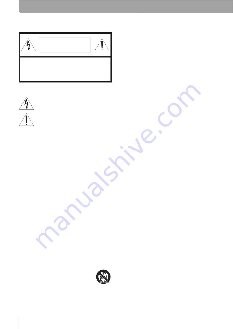
CAUTION

RISK OF ELECTRIC SHOCK 

DO NOT OPEN

CAUTION: TO REDUCE THE RISK OF 

ELECTRIC SHOCK, DO NOT REMOVE 

COVER (OR BACK). NO USER-SERVICEABLE 

PARTS INSIDE. REFER SERVICING TO 

QUALIFIED SERVICE PERSONNEL.

• Explanation of Graphical Symbols

This graphic symbol is intended to alert you to the 
presence of uninsulated “dangerous voltage” within the 
product’s enclosure that may be of sufficient magnitude 
to constitute a risk of electric shock to persons.

This graphic symbol is intended to alert you to the 
presence of important operating and maintenance 
(servicing) instructions in the literature accompanying 
the appliance.

1

Read Instructions – All the safety and operating 
instructions should be read before you operate the 
product.

2

Retain Instructions – The safety and operating 
instructions should be retained for future reference.

3

Heed Warnings – All warnings on the product and in the 
operating instructions should be adhered to.

4

Follow Instructions – All operating and use instructions 
should be followed.

5

Cleaning – Unplug this product from the PC before 
cleaning. Do not use liquid cleaners or aerosol cleaners.

6

A t t a c h m e n t s   –   D o   n o t   u s e   a t t a c h m e n t s   n o t 
recommended by the product manufacturer as they may 
cause hazards.

7

Water and Moisture – Do not use this product near water 
– near a bath tub, wash bowl, kitchen sink, or laundry 
tub; in a wet basement; or near a swimming pool; and 
the like.

8

Accessories – Do not place this product on an unstable 
cart, stand, tripod, bracket, or table. The product may 
fall, causing serious injury to a child or adult, and 
serious damage to the product. Use only with a cart, 
stand, tripod, bracket, or table recommended by the 
manufacturer, or sold with the product. Any mounting of 
the product should follow the manufacturer’s instructions, 
and should use a mounting accessory recommended 
by the manufacturer.

9

A product and cart combination should be moved 
with care. Quick stops, excessive force, and uneven 
surfaces may cause the product and cart combination 
to overturn.

10 Ventilation – Slots and openings in the cabinet are 

provided for ventilation and to ensure reliable operation 
of the product and to protect it from overheating, and 
these openings must not be blocked or covered. The 
openings should never be blocked by placing the 
product on a bed, sofa, rug, or other similar surface. This 
product should not be placed in a built-in installation 
such as a bookcase or rack unless proper ventilation is 
provided or the manufacturer’s instructions have been 
adhered to.

11 Power Sources – This product should be operated only 

from the type of power source indicated on the marking 
label. If you are not sure of the type of power supply 
to your home, consult your product dealer or local 
power company. For products intended to operate from 
battery power, or other sources, refer to the operating 
instructions.

12 USB cable Protection – USB cable should be routed so 

that they are not likely to be walked on or pinched by 
items placed upon or against them, paying particular 
attention to cords at plugs, convenience receptacles, 
and the point where they exit from the product.

13 Lightning – For added protection for this product during 

a lightning storm, or when it is left unattended and 
unused for long periods of time, unplug it from the PC 
and disconnect the antenna or cable system. This will 
prevent damage to the product due to lightning and 
power-line surges.

14 Power Lines – An outside antenna system should not be 

located in the vicinity of overhead power lines or other 
electric light or power circuits, or where it can fall into 
such power lines or circuits. When installing an outside 
antenna system, extreme care should be taken to keep 
from touching such power lines or circuits as contact 
with them might be fatal.

15 Object and Liquid Entry – Never push objects of any 

kind into this product through openings as they may 
touch dangerous voltage points or short-out parts that 
could result in a fire or electric shock. Never spill liquid 
of any kind on the product.

16 Servicing – Do not attempt to service this product 

yourself as opening or removing covers may expose 
you to dangerous voltage or other hazards. Refer all 
servicing to qualified service personnel.

17 Damage Requiring Service – Unplug this product from 

the PC and refer servicing to qualified service personnel 
under the following conditions:

a) When the USB cable is damaged,

b) If liquid has been spilled, or objects have fallen into 

the product,

c) If the product has been exposed to rain or water,

i

Summary of Contents for PJP-CAM1

Page 1: ...ntroller screen to the top 8 Configuring the Video Output Format setting 8 Saving setting information 9 Importing setting information 9 Checking the PJP CAM1 Controller version 9 Auto Switch Shooting Mode 10 Shooting the front image Front Mode 10 Shooting the entire circumference Upside Mode 11 Shooting the document OHP Mode 12 Using the camera in handheld style Release Mode 13 Manual Shooting Mode...

Page 2: ...protect it from overheating and these openings must not be blocked or covered The openings should never be blocked by placing the product on a bed sofa rug or other similar surface This product should not be placed in a built in installation such as a bookcase or rack unless proper ventilation is provided or the manufacturer s instructions have been adhered to 11 Power Sources This product should ...

Page 3: ...his manual meets FCC requirements Modifications not expressly approved by Yamaha may void your authority granted by the FCC to use the product 2 IMPORTANT When connecting this product to accessories and or another product use only high quality shielded cables Cable s supplied with this product MUST be used Follow all installation instructions Failure to follow instructions could void your FCC autho...

Page 4: ...ed 11 Condensation will form when the surrounding temperature changes suddenly Disconnect the USB cable then leave the unit alone 12 When using the unit for a long time the unit may become warm Disconnect the USB cable then leave the unit alone for cooling 13 To prevent damage by lightning keep the cables disconnected during a lightning storm FOR CANADIAN CUSTOMERS To prevent electric shock match ...

Page 5: ...product includes the following accessories Before using this product make sure you received all of the following parts USB cable x 1 Video cable x 1 Camera stand x 1 Document table x 1 CD ROM x 1 Owner s manual this manual x 1 1 ...

Page 6: ...ers DirectX 8 0 or later when using Windows XP PJP 10 Ver 2 0 or later when using in combination with a PJC Yamaha ProjectPhone Note If your system does not meet the following conditions update the firmware When using in combination with a PC PJP Firmware Compatible OS PJP 50R Ver 1 34 or later Windows XP PJP 100UH Ver 1 40 or later Windows XP Windows Vista PJP 25UR Ver 1 12 or later Windows XP Win...

Page 7: ... cover Remove this before using the camera Camera stand You can fold the camera stand to store easily when not in use Camera USB port Connect to the computer using the USB cable MIC terminal Reserved for future extension VIDEO terminal Outputs video signals Controls and Functions 3 ...

Page 8: ... starts 3 Click Next The License agreement screen appears 4 Read the contents carefully and then click Yes The message prompting you to connect this unit appears If you do not agree with the contents of the license agreement click No to cancel the installation 5 Connect this unit to the computer using the supplied USB cable The installation starts Tip Although a warning message regarding hardware ...

Page 9: ...age appears 5 Click Finish Tip If the message to reboot the computer appears reboot it Checking the status of this unit After the connection is complete follow the procedure below to check whether the computer recognizes this unit properly 1 From the taskbar select Start Control Panel System Hardware tab Device Manager The Device Manager screen appears Note If the System icon is not displayed in t...

Page 10: ...be changed In this case select Start All Programs YAMAHA PJP CAM1 Camera Driver PJP CAM1 Settings to start it Basic Operations This chapter describes how to operate the basic functions of this unit 3 Right click and then select Show Controller The PJP CAM1 Controller screen appears 4 Configure the settings Change the settings of this unit according to the use environment To quit the PJP CAM1 Contro...

Page 11: ...e shooting mode between Auto auto switch shooting mode and Manual manual shooting mode Camera Mode display Shows the camera mode currently selected This function is available only when the Auto tab is selected Zoom buttons Adjust the zoom setting Control buttons Configure the shooting method The functions of these buttons change depending on the camera mode Position Adjustment buttons Adjust the po...

Page 12: ... image quality Note When a blue screen appears this unit is being used by another application To close the PJP CAM1 screen Repeat the above step Moving the PJP CAM1 Controller screen to the top Follow the procedure below to set the PJP CAM1 Controller screen always on the top of the desktop 1 From the menu bar of the PJP CAM1 Controller screen select File Settings The Settings screen appears 2 Che...

Page 13: ... Importing setting information Follow the procedure below to import setting information from a file 1 From the menu bar of the PJP CAM1 Controller screen select File Import The Open screen appears 2 Select a file of which information is imported and then click Open The setting information is imported Checking the PJP CAM1 Controller version In the PJP CAM1 Controller screen select File About PJP CAM...

Page 14: ...de This mode is for shooting the front image of participants You can adjust the shooting position in the PJP CAM1 Controller screen 1 Select the Auto tab 2 Turn the camera to the front Automatically switches to Front Mode 3 Use the Control buttons to select the shooting method Selects the default shooting range Selects the maximum shooting range 4 Use the Zoom buttons and Position Adjustment butto...

Page 15: ...rn the camera upward Automatically switches to Upside Mode 3 Use the Control buttons to select the shooting method Displays the partial image Displays the entire circumference in double column panoramic format Displays the entire circumference in hemispheric format 4 Use the Zoom buttons and Position Adjustment buttons to adjust the shooting position Note You cannot adjust the shooting position wh...

Page 16: ... 2 Turn the camera downward Automatically switches to OHP Mode 3 Attach the supplied document table to this unit Fit the cut on the document table to the camera stand 4 Use the Control buttons to select the shooting method Configures the field angle suited for A5 148 x 210 mm documents Rotates the image by 90 degrees 5 Use the Zoom buttons to adjust the shooting position 12 ...

Page 17: ...hile holding down the Release button rotate the camera to release it Automatically switches to Release Mode 3 Direct the camera toward the subject 4 Use the Zoom buttons to adjust the shooting position To select the default shooting range click To install the camera 1 Attach the camera to the camera stand so that the marks face each other 2 While holding down the Release button rotate the camera t...

Page 18: ...he camera 3 Use the Control buttons to select the shooting method Displays the image with the maximum field angle setting Displays the entire circumference in double column panoramic format Displays the entire circumference in hemispheric format 4 Use the Zoom buttons to adjust the shooting position Note You cannot adjust the shooting position when selecting or 14 ...

Page 19: ...puter To connect a PJP 50R Refer to PJP 50R Audio Driver Instruction Manual the PDF file in the PJP 50R AudioDriver folder included in the supplied CD ROM To connect a PJP 100UH PJP 25UR Refer to the instruction manual of your PJP Note To use a PJP 25UR you need to run the PJP 25UR Controller Refer to PJP 25UR User s Manual Tip When using this unit in combination with a PJC refer to ProjectCast In...

Page 20: ...cking box Tip To adjust the shooting position without the auto tracking function use the Orientation Selection radio button Auto tracking shooting in all directions Follow the procedure below to shoot an image of the entire circumference and switch the display image automatically based on the talker s position detected by the PJP s microphones 1 In the PJP CAM1 Controller screen select the Auto ta...

Page 21: ...s of this product Uploading or posting this program at a website accessible by the general public is prohibited unless you have permission from Yamaha 3 Production of duplicates You may only duplicate this program for the purpose of backup or when upgrading multiple units of this product 4 Inhibition of decompiling reverse engineering or disassembling You may not decompile reverse engineer disasse...

Page 22: ...1 Controller screen select File PJP CAM1 Firmware Update The PJP CAM1 License Agreement screen appears 2 Read the contents carefully select Accept all terms of the license agreement and then click OK The PJP CAM1 Firmware Update screen appears If you do not agree with the contents of the license agreement click Don t accept the license agreement to cancel the firmware update 3 Select Download from ...

Page 23: ...s 1 From the menu bar of the PJP CAM1 Controller screen select File PJP CAM1 Firmware Update The PJP CAM1 License Agreement screen appears 2 Read the contents carefully select Accept all terms of the license agreement and then click OK The PJP CAM1 Firmware Update screen appears If you do not agree with the contents of the license agreement click Don t accept the license agreement to cancel the fir...

Page 24: ...0 to 85 no condensation Radio interference standard FCC Part 15 Class A US EN55022 Class A EU USB port mini USB port USB1 1 Video output interface Video NTSC PAL Connector mini jack External microphone input interface Connector mini jack monaural plug in power Camera 1 2 type single plate CMOS Approx 3 15 million pixels diagonal field angle 180 degrees Accessories USB cable x 1 Video cable x 1 Came...

Page 25: ...M LUXEMBOURG Yamaha Music Central Europe GmbH Branch Benelux Clarissenhof 5 b 4133 AB Vianen The Netherlands Tel 0347 358 040 FRANCE Yamaha Musique France BP 70 77312 Marne la Vallée Cedex 2 France Tel 01 64 61 4000 ITALY Yamaha Musica Italia S P A Viale Italia 88 20020 Lainate Milano Italy Tel 02 935 771 SPAIN PORTUGAL Yamaha Musica Iberica S A Ctra de la Coruna km 17 200 28230 Las Rozas Madrid S...

Page 26: ...YAMAHA CORPORATION 10 1 Nakazawa cho Hamamatsu Shizuoka 430 8650 Japan 2008 All rights reserved As of March 2008 Printed in Japan WN33390 ...

Reviews: