background image

PING-PONG RECORDING

Ping-pong recording is a technique you can use to squeeze more than just 4 parts onto your 4-track machine.
This is accomplished by re-recording a mix of existing tracks onto an open track. Once tracks have been combined in this

way on a new track, the original tracks can be erased, clearing them for additional overdubs,

In ping-pong recording, you can record parts on tracks 1,

2, and 3, for example, and then re-record these tracks
onto track 4, using the mixer controls to set up the right
balance between the 3 original tracks. You now have a

“mix” of the first 3 tracks on track 4, and tracks 1, 2, and 3
are available for more recording. That’s already the equivalent
of 6 “tracks” on your 4-track recorder. While mixing the

first 3 tracks down onto track 4 you can also mix in a live

instrument via the MT120 mixer section. That would give

you 4 parts recorded on track 4 of the tape. With the 3
tracks you still have available for recording, that’s a total

of 7 tracks. Now, if you record only 2 of the remaining
tracks and ping-pong these to track 3 while mixing in
another live instrument, you’ll have 4 parts on tracks 4, 3
parts on track 3, and 2 tracks available. That’s a total of 9.

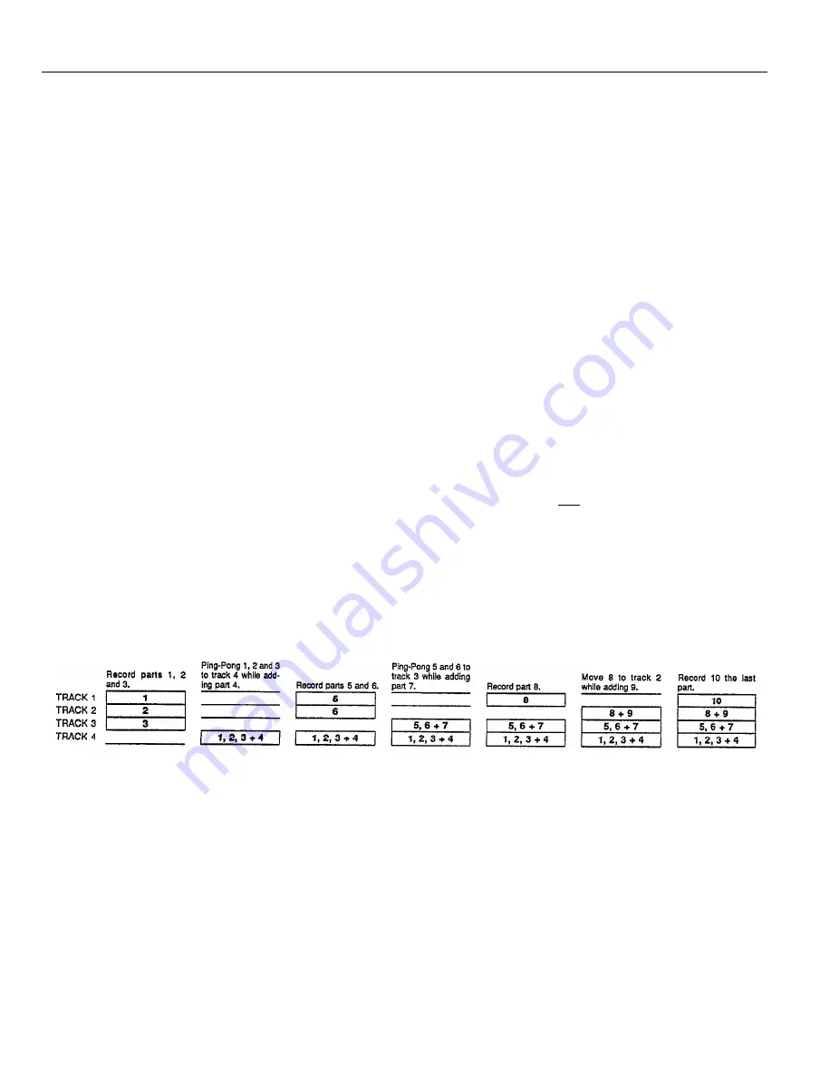
Following this procedure it is actually possible to record
up to 10 individual tracks without re-recording any single

track more than once (refer to the illustration).

[Note] 

Ping-ponging is a critical step because the tracks

to be ping-ponged must be mixed 

perfectly 

before

you can go on to recording the subsequent tracks.
This is because once they’re ping-ponged and

new material has been recorded on the original

tracks, their balance and individual sound 

cannot

be changed unless you go back and record the
original tracks all over again.

[Note] 

It is recommended that you record using the 9.5

cm/sec tape speed with dbx ON if you plan to
combine tracks using the ping-pong technique.

Under some conditions, use of the 4.8 cm/sec

tape speed with noise reduction OFF will cause
feedback when a previously recorded track is re-

recorded onto an adjacent track.

[Note] 

Ping-Pong recording technique requires that multiple

tracks are directed to tape via PAN controls. Re-

member that a signal appearing at the stereo AUX
RETURN will also be added along with the tracks
being recorded or ping-ponged. To prevent an
effect from being recorded, set the AUX RETURN

fader to “0” (all the way off).

EXAMPLE: Recording tracks “1” through “10” using the Ping-pong process.

17

Summary of Contents for MT120

Page 1: ...YAMAHA AUTHORIZED PRODUCT MANUAL MULTITRACK CASSETTE RECORDER ...

Page 2: ...YAMAHA MULTITRACK CASSETTE RECORDER OPERATION MANUAL ...

Page 3: ...not be situated on a bed sofa rug or similar surface that may block the ven tilation openings or placed in a built in installation such as a bookcase or cabinet that may impede the flow of air through the ventilation openings 9 Heat The appliance should be situated away from heat sources such as radiators heat registers stoves or other appliances including amplifiers that produce heat 10 11 12 13 ...

Page 4: ...S DE BRUITS RADIOELECTRIQUES DEPASSANT LES LIMITES APPLICABLES AUX APPAREILS NUMERIQUES DE LA CLASSE B PRESCRITES DANS LE REGLEMENT SUR LE BROUILLAGE RADIOELECTRIQUE EDICTE PAR LE MINISTERE DES COMMUNICATIONS DU CANADA This applies only to products distributed by YAMAHA CANADA MUSIC LTD Dette apparat overholder det gaeldende EF direktiv vedrørende radiostøj Cet appareil est conforme aux prescripti...

Page 5: ...ks at once or in any combination MT120 is the ideal choice for recording bands or layering tracks at home And because it s a YAMAHA you know that the MT120 will give you the very finest sound quality and overall performance available In order to make use of the MT120 s many features and obtain maximum performance we urge you to read this operation manual thoroughly and keep it in a safe place for ...

Page 6: ...ANDLE CABLES CAREFULLY Always plug and unplug cables including the AC cord by gripping the connector not the cord 6 CLEAN WITH A SOFT DRY CLOTH Never use solvents such as benzine or thinner to clean the unit Wipe clean with a soft dry cloth 7 ALWAYS USE THE CORRECT POWER SUP PLY The MT120 is sold with the appropriate power specifi cations for the local area power supply voltage and power consumpti...

Page 7: ...THE CONTROLS AND CONNECTORS CONTROL PANEL FRONT PANEL REAR PANEL 4 MT120 MULTlTRACK CASSETTE RECORDER ...

Page 8: ...levels when recording and to balance mix the sound from the recorder s tracks when playing back a recording Noise and distortion are at their lowest at input fader level 7 REC SELECT Switches The REC SELECT switches are used when recording to assign send the signal from each mixer channel either directly to the corresponding track of the re corder or to a different track via the PAN controls see C...

Page 9: ...the STEREO OUT jacks 6 MT120 MULTITRACK CASSETTE RECORDER MASTER Fader The MASTER fader sets the overall output level of the MT120 mixer section and thus the level of the output signal appearing at the STEREO OUT jacks The MAS TER fader also affects recording level when any of the mixer section s channels are assigned to the record er s tracks via the PAN controls see SETTlNG RE CORDING LEVELS on ...

Page 10: ...back Note When switched ON the graphic equalizer can affect signals being routed to tape via the PAN controls when the REC SELECT switches which are set to L or R The graphic equalizer will not affect signals being routed to tape via REC SE LECT switches which are set to 1 4 Transport Controls These light touch electronic transport controls provide smooth sure control of the tape transport functio...

Page 11: ...old the cassette with the open end the end at which you can see tape facing the transport controls First press the rear edge of the cassette DOWN and UNDER the central retaining finger at the rear of the cassette com partment Then gently press the front of the cassette DOWN to seat the cassette in place SEE DIAGRAM 8 MT120 MULTITRACK CASSETTE RECORDER Note Since the MT120 uses the entire width of ...

Page 12: ... connector MONITOR OUT R and L Jacks These jacks output the same signal fed to the PHONES jack at line level Control the level volume of the output using the MONITOR PHONES control The MONITOR OUT jacks can be connected to a stereo sound system for monitoring and listening They are RCA pin type jacks POWER Switch Press the POWER switch once to turn power ON a second time to turn power OFF When the...

Page 13: ...CONNECTION EXAMPLES BASIC CONNECTIONS Make sure the power to all equipment is OFF when making connections 10 MT120 MULTITRACK CASSETTE RECORDER ...

Page 14: ...necessary to break out the tabs for both the A and B sides of the tape When you d like to record over a tape with the tabs broken out just cover the holes where the tabs were with a small piece of adhesive tape PREVENTING ACCIDENTAL TAPE ERASURE l l Taking up tape slack If the tape in the cassette is slack or some portion of the tape is out of the cassette shell there is a risk it may become tangl...

Page 15: ...Tracks a Select channel to track assignment for each overdub b Set records level for each overdub c Record the overdub 3 Track Combining a If necessary use ping pong technique to combine tracks and clear them for additional overdubs 4 Mixdown a Set up for monitoring the mix b Set up a rough mix and add effects c Finalize and rehearse the mix d Connect the MT120 STEREO OUT jacks to a stereo cassett...

Page 16: ...ctly to track 1 of the recorder This applies in the same way to all other channels and tracks The panned channel to track assignment method makes it possible to assign several of the mixer s channels to a single recorder track or single mixer channels can be assigned to a track of a different numbers Each of the REC SELECT switches has either an L or R position These correspond to the left L and r...

Page 17: ...ording because it allows you to listen to the four tape tracks while leaving input faders available to route signal sources to tape Material already recorded on any of the recorder s tracks is delivered to the PHONES jack and MONITOR OUT jacks via the corresponding MONITOR controls In this case an input source can only be heard when it is assigned to a track via the appropriate REC SELECT switch a...

Page 18: ... set at about 7 or 8 on its scale to achieve the above mentioned meter reading This is to ensure the best possible signal to noise ratio and allow plenty of plus and minus leeway for later adjustment If the fader setting is way off try adjusting the volume control on the instrument or other source until you can get the optimum reading with a fader setting between 7 and 8 After levels are set press...

Page 19: ...to track assignment for the new track 4 Check your monitor settings to ensure that you can monitor the previously recorded track s as well as the new track to be recorded the MONITOR SELECT switch should normally be set to MONITOR 5 Set the recording level for the new track 6 You can now rehearse the overdub without actually recording by simply playing back the already recorded track s and playing...

Page 20: ...s on tracks 4 3 parts on track 3 and 2 tracks available That s a total of 9 Following this procedure it is actually possible to record up to 10 individual tracks without re recording any single track more than once refer to the illustration Note Ping ponging is a critical step because the tracks to be ping ponged must be mixed perfectly before you can go on to recording the subsequent tracks This ...

Page 21: ...ER fader setting until you can hear the tracks you ve recorded and the channel 4 meter reads around 0 on the meter scale Adjust the MONITOR 4 control for the most com fortable monitoring level 2 Adjust the input 1 2 and 3 faders carefully until you get the desired balance between the first three tracks You ll notice that as you adjust the balance between tracks the channel 4 meter reading might ch...

Page 22: ...e and adjust the sound of each track individually This simply means raising the fader of a single track adding effects or other signal processing as required then repeating the process on the next track until all tracks have been carefully checked MT120 s 5 band GRAPHIC EQUALIZER can be used to add or subtract high mid and low frequency components from the overall mix creating a more exciting and ...

Page 23: ... sent to the equalizer Therefore it can be used during ping pong recording mixdown operation and when recording with the REC SELECT control set to L or R The equalizer cannot be used when the REC SELECT control is set to 1 4 however since each channel signal is recorded directly on the appropriate track The graphic equalizer affects only the signal paths marked with bold lines in the diagram below...

Page 24: ...uts to an external mixer In mixdown individual tracks can be processed using a signal processor which receives signal from the TAPE OUT jack and the output of which is returned to a channel s INPUT jack See diagram Processing Individual Tracks In Mixdown Using TAPE OUT Jacks 21 ...

Page 25: ...TURN jacks can be adjusted using the AUX RETURN control and the resulting signal is combined with the MT120 s main stereo output signal Since the returned effect signal is combined with the mixer s stereo output signal the AUX SEND RETURN loop can be used in mixdown to add an effect to tracks when they are being recorded In this case tracks must be assigned to tape using the panned channel to trac...

Page 26: ... mode punch out by switching the REC SELECT switch for that track to OFF The red REC PAUSE LED will begin to flash Footswitch Punch in out 1 Plug a YAMAHA FC4 or FC5 optional footswitch into the MT120 PUNCH l O jack 2 Set the REC SELECT switch for the track to be punched in to the appropriate record position and press the REC PAUSE button to activate the rec pause mode The red REC PAUSE LED should...

Page 27: ...wing problems l Recording playback and erasure are not possible l Reduced playback sound level l Fluctuating and or distorted sound l Excessive noise l A drop in level at the high frequencies If any of the above problems occur clean the heads careful before assuming the fault is with the recorder Use a commercially available head cleaning kit read the instructions provided with the kit or wipe car...

Page 28: ... AUX RETURN level control nominal 16 dB AUX RETURN level control max 1 k ohm Greater than 10 k ohms 10 dB into 50 k ohms 8 to 40 ohms 45 mW 45 mW 40 ohms 1 k ohm Greater than 10 k ohms 10 dB into 50 k ohms 1 k ohm Greater than 10 k ohms 10 dB into 50 k ohms 1 k ohm Greater than 10 k ohms 10 dB into 50 k ohms ELECTRICAL SPECIFICATIONS Frequency Response NR OUT S N ratio 3 THD Level Distortion Chann...

Page 29: ...BLOCK DIAGRAM ...

Page 30: ......

Page 31: ...aitteen toisiopiiriin kytketty käyttökytkin ei irroita koko laitetta verkosta AVVERTENZA L apparecchio rimane sotto tensione anche quando è spento tramite I interuttore principale SERVICE This product is supported by YAMAHA s worldwide network of factory trained and qualified dealer service personnel In the event of a problem contact your nearest YAMAHA dealer ENTRETIEN L entretien de cet appareil...

Page 32: ...YAMAHA 9202 R4 Printed in Japan ...

Page 33: ...YAMAHA Yamaha Corporation of America 6600 Orangethorpe Avenue P O Box 6600 Buena Park CA 90622 6600 9 15 26680 Recyclable ...

Reviews: