background image

4. Screens

MMP1 Operation Manual

11

HPF cutoff 
frequency

Drag or use the mouse wheel to change 
the HPF cutoff frequency. To return the 
setting to 80 Hz, simultaneously hold 
down the <Ctrl> key (Windows) or the 
<command> key (Mac) and click on the 
control.

LPF

Click to turn the LPF (Low Pass Filter) on 
(green) or off.

LPF cutoff 
frequency

Drag or use the mouse wheel to change 
the LPF cutoff frequency. To return the 
setting to 16 kHz, simultaneously hold 
down the <Ctrl> key (Windows) or the 
<command> key (Mac) and click on the 
control.

INSERT

Click to turn the Insert on (green) or off.

Send Destination

Select the signal to send to the Insert.

Return Source

Select the signal to be returned from the 
Insert.

(Insert) Trim

Drag or use the mouse wheel to adjust 
signal levels to be sent to the Insert. To 
return the setting to 0 dB, simultaneously 
hold down the <Ctrl> key (Windows) or 
the <command> key (Mac) and click on 
the control.

SIGNAL CHAIN

Displays the signal processors applied to 
audio signals in the order in which they 
are applied (descending order).

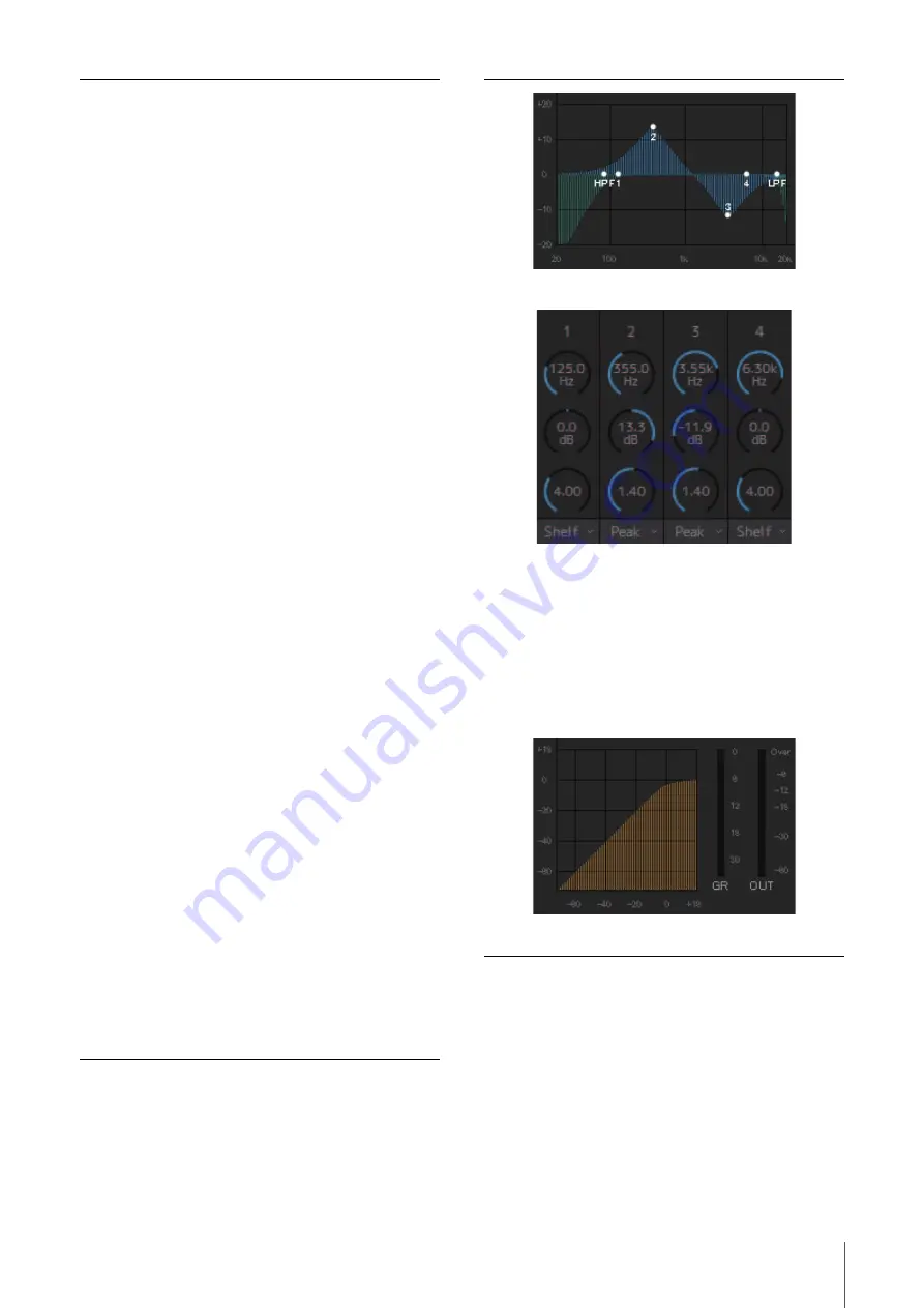
EQ

Click to turn the EQ on (green) or off.
You can choose from the following four EQ 
algorithms. The color of the bar at the 
bottom of the EQ graph will change based 
on the algorithm selected.

PRECISE

This EQ strives for ultimate precision and 
controllability. It enables you to adjust the 
target point precisely, and flexibly satisfies 
various requirements for sound making. 
Low/High Shelving filters feature a “Q” 
parameter, which enables you to adjust 
the knee characteristics.

AGGRESSIVE

This EQ is musical and effective. It 
enables you to add a powerful, creative 
edge and serves as a powerful tool for 
artistic expression.

SMOOTH

This EQ focuses on smooth sound 
qualities. It contributes to a natural sound 
without changing the atmosphere of the 
original.

LEGACY

This is the standard EQ that has been 
provided on Yamaha digital mixers since 
the PM1D and PM5D.

Displays the EQ graph and filters.

Drag or use the mouse wheel to change four band EQ 
parameters (Frequency, Gain, Q). To return these parameters to 
their default values, simultaneously hold down the <Ctrl> key 
(Windows) or the <command> key (Mac) and click on the 
corresponding control. Default values are F: 125 Hz/355 Hz/
3.55 kHz/6.3 kHz, G: 0 dB, and Q: 4.0 (Shelf)/1.4 (Peak)/1.0 
(Notch). You can also select the EQ type from Peak and Shelf 
(Shelving), or Peak and Notch.

COMP

Click to turn the compressor on (green) or 
off.

Displays the COMP graph together with the GR meter and the 
OUT meter.

Summary of Contents for MMP1

Page 1: ...Find or Search from the Acrobat Reader Edit menu and enter a key word to locate the related information anywhere in the document You can also click on desired items and topics you want to refer to in...

Page 2: ...reen 51 5 Configuring System Settings 52 5 1 Basic settings example 52 5 2 Bass Management 59 5 3 Lip Sync Delay 60 5 4 Commentary functions 61 6 Appendix 64 6 1 Error messages 64 6 2 MMP1 Editor keyb...

Page 3: ...latency cue mix 3 Speaker Management function max 32x32 matrix This adjusts monitor signals The matrix input stage comes with a bass management crossover filter to allow for unrestricted bass managem...

Page 4: ...P1 Controller for iPad Connect the MMP1 Controller to the MMP1 on your network one unit for convenience and ease in controlling certain MMP1 functions NOTE Before using the MMP1 Controller you will ne...

Page 5: ...itor offline without connection to or control of the MMP1 Exit Closes the MMP1 Editor NIC Select the network interface card connected to the MMP1 to operate Device Select the MMP1 to operate Click the...

Page 6: ...E Only the MMP1 Editor can be used to configure basic settings Basic settings must be configured on the MMP1 Editor before the MMP1 Controller can be used 1 Select file icon on the menu bar then selec...

Page 7: ...s when changing Scenes Error icon Cooling fan has stopped Please contact your Yamaha dealer and have qualified Yamaha service personnel inspect the cooling fan The backup battery voltage is reduced Pl...

Page 8: ...l strips For setting EQ compressor insert pan output level and other values for each channel strip User Assignable functions For displaying and enabling operation of User Assignable functions Click th...

Page 9: ...el strip and then set the parameters in the Selected Channel tab on the Main screen To bring up the context menu for Windows right click anywhere within the section or for Mac hold down the control ke...

Page 10: ...range values entered will be corrected to the maximum or minimum value allowed You can also use the mouse wheel to change the output level Channel name Enter a channel name of up to 17 alphanumeric ch...

Page 11: ...color of the bar at the bottom of the EQ graph will change based on the algorithm selected PRECISE This EQ strives for ultimate precision and controllability It enables you to adjust the target point...

Page 12: ...1 and 2 while muting outputs from Main Monitor 3 onwards When PFL is on signals will not be sent to the Main Monitors even when this button is turned on MUTE Click to turn mute on yellow or off PAN Dr...

Page 13: ...ctly Out of range values entered will be corrected to the maximum or minimum value allowed NOTE You can use the mouse wheel while holding down Shift to make minor adjustments Changing this value will...

Page 14: ...pear and function as An on off button an latch type button that switches on and off each time you click it A push button a momentary type button that works while the button is held down A display indi...

Page 15: ...on the Settings screen The signal position displayed on the meters can be selected in the System tab of the Scene tab on the Settings screen Meters Displays Monitor Matrix Out meters Monitor section F...

Page 16: ...the setting to 0 dB simultaneously hold down the Ctrl key Windows or the command key Mac and click on the control Click MUTE to mute Studio Speaker Output Trim Drag or use the mouse wheel to adjusts...

Page 17: ...e MISC tab of the Scene tab on the Settings screen Store Click to store a Snapshot at the selected location Recall Click to recall load the selected Snapshot Name Click to select a Snapshot or an empt...

Page 18: ...x In to Out on green or off and setting Send levels Source For selecting monitor matrix input sources NOTE The same items can be configured on the Input Patch tab on the Patch screen Type No The Monit...

Page 19: ...nitor Matrix tab of the Scene tab on the Settings screen you cannot set Monitor Sources 1 8 to send to the Main Monitor Downmix L R or Headphone L R on this screen Use the Monitor Control tab on the M...

Page 20: ...er Matrix Out Displays Speaker Matrix Out names Speaker Matrix In For selecting input sources and adjusting the levels of the selected input sources Speaker matrix Click to turn Send on purple or off...

Page 21: ...rossover filter type in the Speaker Matrix tab of the Scene tab on the Settings screen The color of the text will be orange when the FIR filter is temporarily changed to the IIR filter with the talkba...

Page 22: ...d This is used to switch between Speaker Sets when the speaker matrix is being used for another application Speaker Set Displays the Speaker Set to which the Speaker Matrix Out belongs NOTE You can se...

Page 23: ...s higher than 96 kHz You can change the sample rate in the MISC tab of the Scene tab on the Settings screen You can select the format for Monitor Sources 1 8 and Cue Sources 1 8 from the Monitor Matri...

Page 24: ...key Mac on the Source fields drag up or down on the fields to select several input sources at the same time Dante Out For selecting the audio signal output from the Dante PRIMARY SECONDARY connectors...

Page 25: ...gnals to the channel strip are output directly without passing through the channel strip Monitor Matrix Meter Out 1 32 Main Monitor Cue Studio Speaker and AUX signals output to the meter Downmix Meter...

Page 26: ...o 17 alphanumeric characters and symbols To bring up the context menu for Windows right click anywhere within the section or for Mac hold down the control key and then click in the section NOTE Set Co...

Page 27: ...x Out type You can configure type settings in Monitor Matrix tab of the Scene tab on the Settings screen Label Double click to set a Monitor Matrix Out or Speaker Matrix Out name Enter a channel name...

Page 28: ...setting is used when applying a FIR filter with bass management configured Select this check to automatically change the FIR filter to an IIR filter when Talkback is turned on Applying an FIR filter f...

Page 29: ...sources CH Type For audio that is output to the monitor speakers the audio sent to the main speakers should be set to Monitor audio sent to LFE channels to LFE and audio used for other applications t...

Page 30: ...set to THRU Cutoff can be selected when the Filter is HPF or LPF IIR Slope Determines filter shoulder characteristics when an IIR filter is applied NOTE Cutoff can be selected when the Filter is HPF...

Page 31: ...interrupt destination from 1 8 Bus Select the mic input used for Talkback Mic 1 and Mic 2 for Bus 1 refer to Talkback Mic In 1 1 and 1 2 on the Patch screen and Mic 1 and Mic 2 for Bus 2 refer to Talk...

Page 32: ...ion set Enter a channel name up to 17 alphanumeric characters and symbols To insert a line break at any point simultaneously hold the Alt key and press Enter Windows or hold the option key and press r...

Page 33: ...splays the RTB Return TalkBack status for the channel strip Oscillator Source Select a frequency or pink noise Select a signal to output from the oscillator This is intended to give users a means of s...

Page 34: ...ctivation The mute and dimmer settings are restored to what they were when turning off the MMP1 Current At the time of MMP1 power activation the monitor level mute and dimmer settings are restored to...

Page 35: ...o MMP1 I O connector I O signals Label Double click to set each input output signal name Enter a channel name up to 17 alphanumeric characters and symbols NOTE Names set here will be used as the signa...

Page 36: ...oltage is High Low Executes the Function when the input voltage is Low On Edge Executes the Function when the input voltage changes from Low to High Off Edge Executes the Function when the input volta...

Page 37: ...s it only to the RTB bus Scene Recall Select the Scene number Recalls the selected Scene Snapshot Recall Select a Snapshot number Recalls the selected Snapshot Talkback Destination Select a Talkback i...

Page 38: ...annel strip is turned on Generic Function Select the GPI Out Function number Enables output when the selected GPI Out Function is turned on System Alarm Enables output when an error occurs with the MM...

Page 39: ...g a Scene or Snapshot when turned off the Scene or Snapshot will be stored recalled without a confirmation message Talkback Button Behavior Click to choose the Talkback Button Behavior see below Latch...

Page 40: ...1 Getting Started for more information about setting the MMP1 unit DIP switch IP address Mode Displays the connection type with the MMP1 unit MAC Address Displays the MAC address for the MMP1 unit Cha...

Page 41: ...nit to be updated NOTE You must log in as an Administrator to update the firmware of the MMP1 unit You can also revert the MMP1 unit s firmware to an earlier version if desired Connect Information Dis...

Page 42: ...or view and displays the Information screen Selects a Scene Switches screens Displays online offline status Tap to display the Select MMP1 dialog box Double tap with two fingers to mute all output Dou...

Page 43: ...channels can be displayed as the send destinations If there are 13 or more channels on the Main Monitor only the first 12 channels will appear here Area 2 of the image will appear differently dependin...

Page 44: ...n red Peak hold circuits are not displayed NOTE Up to 12 Main Monitor channels are displayed If there are 13 or more channels on the Main Monitor only the first 12 channels will appear here Double tap...

Page 45: ...nablefunctions You can also swipe this to change to a meter display This is used to set the left half of the screen to be operated to Main Monitor output This is used to set the left half of the scree...

Page 46: ...Peak hold circuits are not displayed REF Tap to call up the reference level and then hold this down for at least two seconds until the indicator flashes to store the current Monitor Level value as th...

Page 47: ...he PFL Pre Fader Listen bus on green or off Turn this on to send pre fader audio signals to Main Monitors 1 and 2 while muting outputs from Main Monitor 3 onwards AFL Turns output to the AFL After Fad...

Page 48: ...d to audio signals in the order in which they are applied descending order Trim Drag to adjust the output level for the selected channel Double tap to return this value to 0 PFL Turns output to the PF...

Page 49: ...the shoulder characteristics AGGRESSIVE This EQ is musical and effective It enables you to add a positive creative edge and serves as a powerful tool for artistic expression SMOOTH This EQ focuses on...

Page 50: ...mation When turned on green a confirmation dialog box will appear when recalling a Scene and when turned off the Scene will be recalled without a confirmation message Talkback Button Behavior Latch To...

Page 51: ...ormation screen Displays information pertaining to the MMP1 unit Nickname Displays the nickname for the MMP1 unit NOTE This nickname can be set on the Information screen in the MMP1 Editor Version Dis...

Page 52: ...gn where Main Monitor 1 2 is interpreted as L R is recommended 5 1 Basic settings example This example is based on the system outlined in the following block diagram 5 1 1 Preparation 1 Launch the MMP...

Page 53: ...flected on the Monitor Matrix screen 4 Assign an input source to Monitor Source NOTE While holding down the right mouse button Windows or the control key Mac on the Source fields drag up or down on th...

Page 54: ...Patch Assign Speaker Set A 1 6 to Analog Out 1 6 connected to the 5 1 speakers and assign Speaker Set B1 2 to Analog Out 7 8 connected to the stereo speakers 8 Route the Main Monitor output to the Spe...

Page 55: ...hown in the image below Double click the Label field to enter a name Click the Color field to change button color Settings screen Scene User Assignable Create User Assignable buttons for Speaker Set A...

Page 56: ...output and Studio Speaker output needs to be in stereo 13 Assign mic preamp output to a channel strip NOTE While holding down the right mouse button Windows or the control key Mac on the Source fields...

Page 57: ...d to the recording DAW and Cue STU and Headphone Out to AES EBU Out 1 6 connected to the headphones and the speakers The cue mixes are created now 5 1 4 Talkback settings 16 Assign Talkback mic output...

Page 58: ...User Assignable Create User Assignable buttons for Talkback Destination 1 and Talkback Destination 2 to easily turn Talkback on and off from the Main screen 19 Confirm that the buttons for turning Tal...

Page 59: ...ers separately create a separate set of inputs for stereo speakers in addition to the inputs for bass management Since these filters are applied to bass management inputs they are not compatible with...

Page 60: ...images on the video monitor use the lip sync delay function to delay audio output from the Main Monitor to match audio and video content This delay will only apply to the Main Monitor does not apply t...

Page 61: ...igned to Channel Strip In 1 A because the mic preamp output is connected to the ANALOG INPUT 1 connector on the MMP1 2 Configure settings to turn mics on and off using a foot controller or other such...

Page 62: ...ically when the mic is on Settings screen Scene System In the example shown in the image above STU1 output is set to be muted when the channel strip 1 mic is on 5 4 3 Lighting up the On Air sign when...

Page 63: ...trip 1 by bypassing the mic audio mute function The parameter 1 signifies channel strip 1 2 Confirm that the Cough Mute Override button disabling the mic on off function for mic users appears on the M...

Page 64: ...s that can be connected with the MMP1 Editor has been reached Error Another error occurred Message Description Incorrect password The password you entered is incorrect Maximum number of channels excee...

Page 65: ...trl 3 command 3 Displays the Monitor Matrix screen Ctrl 4 command 4 Displays the Speaker Matrix screen Ctrl 5 command 5 Displays the Speaker Management screen Ctrl 6 command 6 Displays the Patch scree...

Page 66: ...tting 21 Function 32 G General 34 GPI 36 GPI In 36 GPI IN functions 37 GPI Out 36 GPI OUT functions 38 H Headphone Monitor Level 13 45 HPF 10 49 HPF LPF EQ tabs 49 I IIR Slope 30 Information screen 40...

Page 67: ...15 17 Source 18 20 29 SOURCE A SOURCE B 10 48 Source Label 18 Speaker Allocation 30 Speaker Label 50 Speaker Management screen 22 Speaker Matrix 29 Speaker Matrix screen 20 Speaker Set 22 SPL 43 45 S...

Reviews: