


BASIC SERVICE INFORMATION
1-27
EAS30402
ELECTRICAL SYSTEM
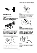
Electrical parts handling
NOTICE
ECA16600
Never disconnect a battery lead while the en-
gine is running; otherwise, the electrical
components could be damaged.
NOTICE
ECA16751
When disconnecting the battery leads from
the battery, be sure to disconnect the nega-
tive battery lead first, then the positive bat-
tery lead. If the positive battery lead is
disconnected first and a tool or similar item
contacts the vehicle, a spark could be gener-
ated, which is extremely dangerous.
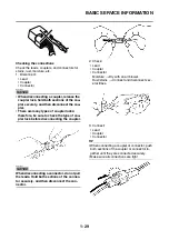
TIP
If a battery lead is difficult to disconnect due to
rust on the battery terminal, remove the rust us-
ing hot water.
NOTICE
ECA16760
Be sure to connect the battery leads to the
correct battery terminals. Reversing the bat-
tery lead connections could damage the
electrical components.
NOTICE
ECA16771
When connecting the battery leads to the
battery, be sure to connect the positive bat-
tery lead first, then the negative battery lead.
If the negative battery lead is connected first
and a tool or similar item contacts the vehi-
cle while the positive battery lead is being
connected, a spark could be generated,
which is extremely dangerous.
NOTICE
ECA16610
Turn the main switch to “OFF” before dis-
connecting or connecting an electrical com-
ponent.
Summary of Contents for MBK XMAX 2014
Page 1: ...2014 SERVICE MANUAL YP125R YP125RA 2DM F8197 E0 ...
Page 6: ......
Page 8: ......
Page 64: ...TIGHTENING TORQUES 2 17 Muffler tightening sequence 1 2 3 ...
Page 72: ...LUBRICATION SYSTEM DIAGRAMS 2 25 EAS2DM1116 LUBRICATION SYSTEM DIAGRAMS 1 2 3 4 5 3 ...
Page 78: ...CABLE ROUTING 2 31 Steering head front view 1 2 3 4 5 6 8 8 A 7 7 ...
Page 80: ...CABLE ROUTING 2 33 Front brake left side view for YP125R 1 2 2 1 1 2 2 D E A B C ...
Page 82: ...CABLE ROUTING 2 35 Front brake left side view for YP125RA 2 1 1 2 1 2 2 A B D E C ...
Page 92: ...CABLE ROUTING 2 45 Frame right side view 3 2 4 1 2 3 A B 6 5 3 A B 3 3 2 3 3 A A B A B B 3 ...
Page 94: ...CABLE ROUTING 2 47 Engine right side view 6 6 6 6 C D C D D C 10 B 9 5 6 1 2 8 3 4 5 6 7 A ...
Page 98: ...CABLE ROUTING 2 51 Frame left side view C D C D 2 1 E 1 2 D C 6 1 4 5 3 2 1 7 3 2 1 A B ...
Page 100: ...CABLE ROUTING 2 53 Engine left side view 1 1 1 1 1 2 3 4 5 6 7 8 9 7 7 A B A B A B 1 ...
Page 106: ...CABLE ROUTING 2 59 Rear brake right side view 2 2 2 2 2 2 1 1 2 3 A B C 3 ...
Page 110: ...CABLE ROUTING 2 63 ...
Page 228: ...REAR SHOCK ABSORBER ASSEMBLIES AND SWINGARM 4 89 ...
Page 231: ......
Page 291: ...CRANKSHAFT 5 60 a 1 ...
Page 292: ...CRANKSHAFT 5 61 ...
Page 302: ...WATER PUMP 6 9 ...
Page 313: ......
Page 331: ...CHARGING SYSTEM 8 18 ...
Page 349: ...COOLING SYSTEM 8 36 ...
Page 391: ...FUEL PUMP SYSTEM 8 78 ...
Page 400: ...IMMOBILIZER SYSTEM 8 87 a Light on b Light off ...
Page 401: ...IMMOBILIZER SYSTEM 8 88 ...
Page 405: ...ABS ANTI LOCK BRAKE SYSTEM for YP125RA 8 92 ...
Page 439: ...ABS ANTI LOCK BRAKE SYSTEM for YP125RA 8 126 ...
Page 464: ...ELECTRICAL COMPONENTS 8 151 ...
Page 476: ......
Page 477: ......
Page 478: ......


