CYLINDER AND PISTON
5-26
EAS2DM1045
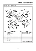
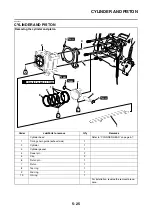
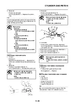
REMOVING THE PISTON
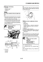
1. Remove:
• Piston pin clips “1”
• Piston pin “2”
• Piston “3”
NOTICE
ECA13810
Do not use a hammer to drive the piston pin
out.
TIP
• Before removing the piston pin clips, cover the
crankcase opening with a clean rag to prevent
them from falling into the crankcase.
• Before removing the piston pin, deburr the pis-
ton pin clip groove and the piston pin bore ar-
ea. If both areas are deburred and the piston
pin is still difficult to remove, remove it with the
piston pin puller set “4”.
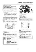
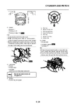
2. Remove:
• Top ring
• 2nd ring
• Oil ring
TIP
When removing a piston ring, open the end gap
with your fingers and lift the other side of the ring
over the piston crown.
EAS2DM1046
CHECKING THE CYLINDER AND PISTON
1. Check:
• Piston wall
• Cylinder wall
Vertical scratches
→
Rebore or replace the
cylinder, and replace the piston and piston
rings as a set.
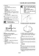
2. Measure:
• Piston-to-cylinder clearance
▼▼▼
▼
▼ ▼▼▼
▼
▼ ▼▼▼
▼
▼ ▼▼▼
▼
▼ ▼▼▼
▼
▼ ▼▼▼
▼
▼▼▼
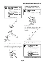
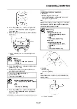
a. Measure cylinder bore “C” with the cylinder
bore gauge.
TIP
Measure cylinder bore “C” by taking side-to-side
and front-to-back measurements of the cylinder.
Then, find the average of the measurements.
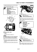
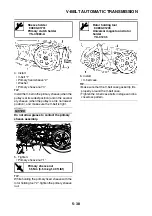
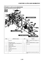
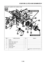
Piston pin puller set
90890-01304
Piston pin puller
YU-01304
1
2
3
Bore
52.000–52.010 mm (2.0472–
2.0476 in)
Taper limit
0.050 mm (0.0020 in)
Out of round limit
0.005 mm (0.0002 in)
“C” = maximum of D
1
–D
2
“T” = maximum of D
1
or D
2
- maximum of D
5
or D
6
“R” = maximum of D
1
, D
3
or D
5
- minimum of
D
2
, D
4
or D
6
Summary of Contents for MBK XMAX 2014
Page 1: ...2014 SERVICE MANUAL YP125R YP125RA 2DM F8197 E0 ...
Page 6: ......
Page 8: ......
Page 64: ...TIGHTENING TORQUES 2 17 Muffler tightening sequence 1 2 3 ...
Page 72: ...LUBRICATION SYSTEM DIAGRAMS 2 25 EAS2DM1116 LUBRICATION SYSTEM DIAGRAMS 1 2 3 4 5 3 ...
Page 78: ...CABLE ROUTING 2 31 Steering head front view 1 2 3 4 5 6 8 8 A 7 7 ...
Page 80: ...CABLE ROUTING 2 33 Front brake left side view for YP125R 1 2 2 1 1 2 2 D E A B C ...
Page 82: ...CABLE ROUTING 2 35 Front brake left side view for YP125RA 2 1 1 2 1 2 2 A B D E C ...
Page 92: ...CABLE ROUTING 2 45 Frame right side view 3 2 4 1 2 3 A B 6 5 3 A B 3 3 2 3 3 A A B A B B 3 ...
Page 94: ...CABLE ROUTING 2 47 Engine right side view 6 6 6 6 C D C D D C 10 B 9 5 6 1 2 8 3 4 5 6 7 A ...
Page 98: ...CABLE ROUTING 2 51 Frame left side view C D C D 2 1 E 1 2 D C 6 1 4 5 3 2 1 7 3 2 1 A B ...
Page 100: ...CABLE ROUTING 2 53 Engine left side view 1 1 1 1 1 2 3 4 5 6 7 8 9 7 7 A B A B A B 1 ...
Page 106: ...CABLE ROUTING 2 59 Rear brake right side view 2 2 2 2 2 2 1 1 2 3 A B C 3 ...
Page 110: ...CABLE ROUTING 2 63 ...
Page 228: ...REAR SHOCK ABSORBER ASSEMBLIES AND SWINGARM 4 89 ...
Page 231: ......
Page 291: ...CRANKSHAFT 5 60 a 1 ...
Page 292: ...CRANKSHAFT 5 61 ...
Page 302: ...WATER PUMP 6 9 ...
Page 313: ......
Page 331: ...CHARGING SYSTEM 8 18 ...
Page 349: ...COOLING SYSTEM 8 36 ...
Page 391: ...FUEL PUMP SYSTEM 8 78 ...
Page 400: ...IMMOBILIZER SYSTEM 8 87 a Light on b Light off ...
Page 401: ...IMMOBILIZER SYSTEM 8 88 ...
Page 405: ...ABS ANTI LOCK BRAKE SYSTEM for YP125RA 8 92 ...
Page 439: ...ABS ANTI LOCK BRAKE SYSTEM for YP125RA 8 126 ...
Page 464: ...ELECTRICAL COMPONENTS 8 151 ...
Page 476: ......
Page 477: ......
Page 478: ......

