


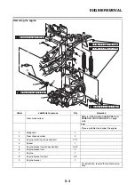
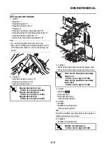


CYLINDER HEAD
5-10
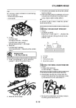
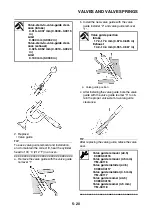
TIP
Do not use a sharp instrument to avoid damag-
ing or scratching:
• Spark plug bore threads
• Valve seats
2. Check:
• Cylinder head
Damage/scratches
→
Replace.
• Cylinder head water jacket
Mineral deposits/rust
→
Eliminate.
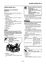
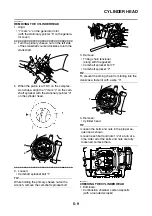
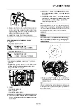
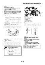
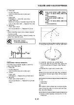
3. Measure:
• Cylinder head warpage
Out of specification
→
Resurface the cylinder
head.
▼▼▼
▼
▼ ▼▼▼
▼
▼ ▼▼▼
▼
▼ ▼▼▼
▼
▼ ▼▼▼
▼
▼ ▼▼▼
▼
▼▼▼
a. Place a straightedge “1” and a thickness
gauge “2” across the cylinder head.
b. Measure the warpage.
c. If the limit is exceeded, resurface the cylinder
head as follows.
d. Place 400–600 grit wet sandpaper on the sur-
face plate and resurface the cylinder head
using a figure-eight sanding pattern.
TIP
To ensure an even surface, rotate the cylinder
head several times.
▲▲▲
▲
▲ ▲▲▲
▲
▲ ▲▲▲
▲
▲ ▲▲▲
▲
▲ ▲▲▲
▲
▲ ▲▲▲
▲
▲▲▲
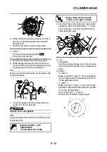
EAS2DM1034
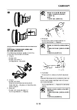
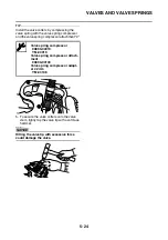
CHECKING THE CAMSHAFT SPROCKET
1. Check:
• Camshaft sprocket
More than 1/4 tooth wear “a”
→
Replace the
camshaft sprocket, timing chain and crank-
shaft as a set.
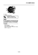
EAS24190
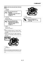
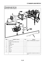
CHECKING THE TIMING CHAIN TENSIONER
1. Check:
• Timing chain tensioner
Cracks/damage
→
Replace.
▼▼▼
▼
▼ ▼▼▼
▼
▼ ▼▼▼
▼
▼ ▼▼▼
▼
▼ ▼▼▼
▼
▼ ▼▼▼
▼
▼▼▼
a. Remove the timing chain tensioner plug.
b. While lightly pressing the timing chain ten-
sioner rod by hand, turn the tensioner rod ful-
ly clockwise with a thin screwdriver “1”.
c. Remove the screwdriver and slowly release
the timing chain tensioner rod.
Warpage limit
0.05 mm (0.0020 in)
1
2
a. 1/4 tooth
b. Correct
1. Timing chain roller
2. Camshaft sprocket
1
Summary of Contents for MBK XMAX 2014
Page 1: ...2014 SERVICE MANUAL YP125R YP125RA 2DM F8197 E0 ...
Page 6: ......
Page 8: ......
Page 64: ...TIGHTENING TORQUES 2 17 Muffler tightening sequence 1 2 3 ...
Page 72: ...LUBRICATION SYSTEM DIAGRAMS 2 25 EAS2DM1116 LUBRICATION SYSTEM DIAGRAMS 1 2 3 4 5 3 ...
Page 78: ...CABLE ROUTING 2 31 Steering head front view 1 2 3 4 5 6 8 8 A 7 7 ...
Page 80: ...CABLE ROUTING 2 33 Front brake left side view for YP125R 1 2 2 1 1 2 2 D E A B C ...
Page 82: ...CABLE ROUTING 2 35 Front brake left side view for YP125RA 2 1 1 2 1 2 2 A B D E C ...
Page 92: ...CABLE ROUTING 2 45 Frame right side view 3 2 4 1 2 3 A B 6 5 3 A B 3 3 2 3 3 A A B A B B 3 ...
Page 94: ...CABLE ROUTING 2 47 Engine right side view 6 6 6 6 C D C D D C 10 B 9 5 6 1 2 8 3 4 5 6 7 A ...
Page 98: ...CABLE ROUTING 2 51 Frame left side view C D C D 2 1 E 1 2 D C 6 1 4 5 3 2 1 7 3 2 1 A B ...
Page 100: ...CABLE ROUTING 2 53 Engine left side view 1 1 1 1 1 2 3 4 5 6 7 8 9 7 7 A B A B A B 1 ...
Page 106: ...CABLE ROUTING 2 59 Rear brake right side view 2 2 2 2 2 2 1 1 2 3 A B C 3 ...
Page 110: ...CABLE ROUTING 2 63 ...
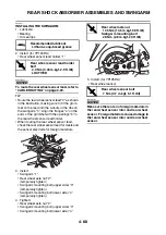
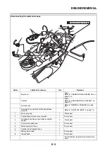
Page 228: ...REAR SHOCK ABSORBER ASSEMBLIES AND SWINGARM 4 89 ...
Page 231: ......
Page 291: ...CRANKSHAFT 5 60 a 1 ...
Page 292: ...CRANKSHAFT 5 61 ...
Page 302: ...WATER PUMP 6 9 ...
Page 313: ......
Page 331: ...CHARGING SYSTEM 8 18 ...
Page 349: ...COOLING SYSTEM 8 36 ...
Page 391: ...FUEL PUMP SYSTEM 8 78 ...
Page 400: ...IMMOBILIZER SYSTEM 8 87 a Light on b Light off ...
Page 401: ...IMMOBILIZER SYSTEM 8 88 ...
Page 405: ...ABS ANTI LOCK BRAKE SYSTEM for YP125RA 8 92 ...
Page 439: ...ABS ANTI LOCK BRAKE SYSTEM for YP125RA 8 126 ...
Page 464: ...ELECTRICAL COMPONENTS 8 151 ...
Page 476: ......
Page 477: ......
Page 478: ......


