


ABS (ANTI-LOCK BRAKE SYSTEM) (for YP125RA)
4-63
EAS2DM1016
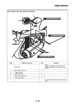
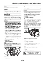
REMOVING THE HYDRAULIC UNIT
ASSEMBLY
NOTICE
ECA2DM1012
Unless necessary, avoid removing and in-
stalling the brake hoses of the hydraulic unit
assembly.
WARNING
EWA13930
Refill with the same type of brake fluid that is
already in the system. Mixing fluids may re-
sult in a harmful chemical reaction, leading
to poor braking performance.
NOTICE
ECA2DM1013
• Handle the ABS components with care,
since they have been accurately adjusted.
Keep them away from dirt and do not sub-
ject them to shocks.
• Do not turn the main switch to “ON” when
removing the hydraulic unit assembly.
• Do not clean with compressed air.
• Do not reuse the brake fluid.
• Brake fluid may damage painted surfaces
and plastic parts. Therefore, always clean
up any spilt brake fluid immediately.
• Do not allow any brake fluid to contact the
couplers. Brake fluid may damage the cou-
plers and cause bad contacts.
• If the union bolts for the hydraulic unit as-
sembly have been removed, be sure to
tighten them to the specified torque and
bleed the brake system.
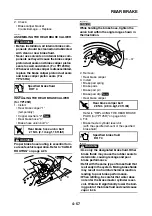
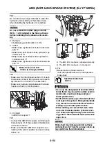
1. Disconnect:
• ABS ECU coupler “1”
TIP
Pull the lock lever “a” of the ABS ECU coupler in
the direction of the arrow shown, and then dis-
connect the coupler.
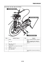
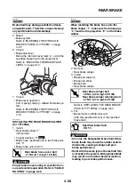
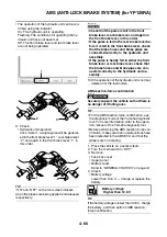
2. Remove:
• Brake hoses
TIP
Do not operate the brake levers while removing
the brake hoses.
NOTICE
ECA2DM1014
When removing the brake hoses, cover the
area around the hydraulic unit assembly to
catch any spilt brake fluid. Do not allow the
brake fluid to contact other parts.
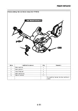
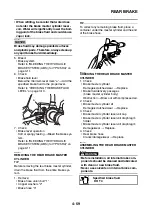
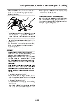
3. Remove:
• Hydraulic unit assembly “1”
TIP
• To avoid brake fluid leakage and to prevent for-
eign materials from entering the hydraulic unit
assembly, insert a rubber plug “a” or a bolt
(M10
×
1.25) into each flare nut hole.
• When using a bolt, do not tighten the bolt until
the bolt head touches the hydraulic unit. Other-
wise, the brake pipe seating surface could be
deformed.
EAS2DM1017
CHECKING THE HYDRAULIC UNIT
ASSEMBLY
1. Check:
• Hydraulic unit assembly
Cracks/damage
→
Replace the hydraulic unit
assembly and the brake hoses that are con-
nected to the assembly as a set.
EAS2DM1018
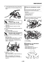
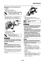
INSTALLING THE HYDRAULIC UNIT
ASSEMBLY
1. Install:
• Hydraulic unit assembly
• Hydraulic unit assembly bracket
a
1
T
R
.
.
Hydraulic unit assembly bolt
7 Nm (0.7 m·kgf, 5.1 ft·lbf)
a
1
Summary of Contents for MBK XMAX 2014
Page 1: ...2014 SERVICE MANUAL YP125R YP125RA 2DM F8197 E0 ...
Page 6: ......
Page 8: ......
Page 64: ...TIGHTENING TORQUES 2 17 Muffler tightening sequence 1 2 3 ...
Page 72: ...LUBRICATION SYSTEM DIAGRAMS 2 25 EAS2DM1116 LUBRICATION SYSTEM DIAGRAMS 1 2 3 4 5 3 ...
Page 78: ...CABLE ROUTING 2 31 Steering head front view 1 2 3 4 5 6 8 8 A 7 7 ...
Page 80: ...CABLE ROUTING 2 33 Front brake left side view for YP125R 1 2 2 1 1 2 2 D E A B C ...
Page 82: ...CABLE ROUTING 2 35 Front brake left side view for YP125RA 2 1 1 2 1 2 2 A B D E C ...
Page 92: ...CABLE ROUTING 2 45 Frame right side view 3 2 4 1 2 3 A B 6 5 3 A B 3 3 2 3 3 A A B A B B 3 ...
Page 94: ...CABLE ROUTING 2 47 Engine right side view 6 6 6 6 C D C D D C 10 B 9 5 6 1 2 8 3 4 5 6 7 A ...
Page 98: ...CABLE ROUTING 2 51 Frame left side view C D C D 2 1 E 1 2 D C 6 1 4 5 3 2 1 7 3 2 1 A B ...
Page 100: ...CABLE ROUTING 2 53 Engine left side view 1 1 1 1 1 2 3 4 5 6 7 8 9 7 7 A B A B A B 1 ...
Page 106: ...CABLE ROUTING 2 59 Rear brake right side view 2 2 2 2 2 2 1 1 2 3 A B C 3 ...
Page 110: ...CABLE ROUTING 2 63 ...
Page 228: ...REAR SHOCK ABSORBER ASSEMBLIES AND SWINGARM 4 89 ...
Page 231: ......
Page 291: ...CRANKSHAFT 5 60 a 1 ...
Page 292: ...CRANKSHAFT 5 61 ...
Page 302: ...WATER PUMP 6 9 ...
Page 313: ......
Page 331: ...CHARGING SYSTEM 8 18 ...
Page 349: ...COOLING SYSTEM 8 36 ...
Page 391: ...FUEL PUMP SYSTEM 8 78 ...
Page 400: ...IMMOBILIZER SYSTEM 8 87 a Light on b Light off ...
Page 401: ...IMMOBILIZER SYSTEM 8 88 ...
Page 405: ...ABS ANTI LOCK BRAKE SYSTEM for YP125RA 8 92 ...
Page 439: ...ABS ANTI LOCK BRAKE SYSTEM for YP125RA 8 126 ...
Page 464: ...ELECTRICAL COMPONENTS 8 151 ...
Page 476: ......
Page 477: ......
Page 478: ......


