


FEATURES
1-3
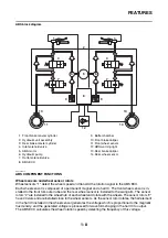
EAS37P1141
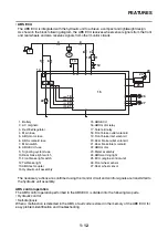
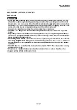
FI SYSTEM
The fuel pump delivers fuel to the fuel injector via the fuel filter. The pressure regulator maintains the
fuel pressure that is applied to the fuel injector at a certain level. Accordingly, when the energizing signal
from the ECU energizes the fuel injector, the fuel passage opens, causing the fuel to be injected into
the intake manifold only during the time the passage remains open. Therefore, the longer the length of
time the fuel injector is energized (injection duration), the greater the volume of fuel that is supplied.
Conversely, the shorter the length of time the fuel injector is energized (injection duration), the lesser
the volume of fuel that is supplied.
The injection duration and the injection timing are controlled by the ECU. Signals that are input from the
throttle position sensor, coolant temperature sensor, lean angle sensor, crankshaft position sensor, in-
take air pressure sensor, intake air temperature sensor, speed sensor (for YP125R), front wheel sensor
(for YP125RA) and O
2
sensor enable the ECU to determine the injection duration. The injection timing
is determined through the signals from the crankshaft position sensor. As a result, the volume of fuel
that is required by the engine can be supplied at all times in accordance with the driving conditions.
1
3
4
14
15
17
18
6
B
5
12
2
7
9
8
10
11
C
13
16
A
1. Fuel pump
2. Pressure regulator
3. Fuel injector
4. Ignition coil
5. Coolant temperature sensor
6. ECU (engine control unit)
7. ISC (idle speed control) unit
8. Throttle position sensor
9. Lean angle sensor
10. Speed sensor (for YP125R)
11. Front wheel sensor (for YP125RA)
12. O
2
sensor
13. Catalytic converter
14. Crankshaft position sensor
15. Intake air pressure sensor
16. Throttle body
17. Intake air temperature sensor
18. Air filter case
A. Fuel system
B. Air system
C. Control system
Summary of Contents for MBK XMAX 2014
Page 1: ...2014 SERVICE MANUAL YP125R YP125RA 2DM F8197 E0 ...
Page 6: ......
Page 8: ......
Page 64: ...TIGHTENING TORQUES 2 17 Muffler tightening sequence 1 2 3 ...
Page 72: ...LUBRICATION SYSTEM DIAGRAMS 2 25 EAS2DM1116 LUBRICATION SYSTEM DIAGRAMS 1 2 3 4 5 3 ...
Page 78: ...CABLE ROUTING 2 31 Steering head front view 1 2 3 4 5 6 8 8 A 7 7 ...
Page 80: ...CABLE ROUTING 2 33 Front brake left side view for YP125R 1 2 2 1 1 2 2 D E A B C ...
Page 82: ...CABLE ROUTING 2 35 Front brake left side view for YP125RA 2 1 1 2 1 2 2 A B D E C ...
Page 92: ...CABLE ROUTING 2 45 Frame right side view 3 2 4 1 2 3 A B 6 5 3 A B 3 3 2 3 3 A A B A B B 3 ...
Page 94: ...CABLE ROUTING 2 47 Engine right side view 6 6 6 6 C D C D D C 10 B 9 5 6 1 2 8 3 4 5 6 7 A ...
Page 98: ...CABLE ROUTING 2 51 Frame left side view C D C D 2 1 E 1 2 D C 6 1 4 5 3 2 1 7 3 2 1 A B ...
Page 100: ...CABLE ROUTING 2 53 Engine left side view 1 1 1 1 1 2 3 4 5 6 7 8 9 7 7 A B A B A B 1 ...
Page 106: ...CABLE ROUTING 2 59 Rear brake right side view 2 2 2 2 2 2 1 1 2 3 A B C 3 ...
Page 110: ...CABLE ROUTING 2 63 ...
Page 228: ...REAR SHOCK ABSORBER ASSEMBLIES AND SWINGARM 4 89 ...
Page 231: ......
Page 291: ...CRANKSHAFT 5 60 a 1 ...
Page 292: ...CRANKSHAFT 5 61 ...
Page 302: ...WATER PUMP 6 9 ...
Page 313: ......
Page 331: ...CHARGING SYSTEM 8 18 ...
Page 349: ...COOLING SYSTEM 8 36 ...
Page 391: ...FUEL PUMP SYSTEM 8 78 ...
Page 400: ...IMMOBILIZER SYSTEM 8 87 a Light on b Light off ...
Page 401: ...IMMOBILIZER SYSTEM 8 88 ...
Page 405: ...ABS ANTI LOCK BRAKE SYSTEM for YP125RA 8 92 ...
Page 439: ...ABS ANTI LOCK BRAKE SYSTEM for YP125RA 8 126 ...
Page 464: ...ELECTRICAL COMPONENTS 8 151 ...
Page 476: ......
Page 477: ......
Page 478: ......


