
4
Replacement
4-11
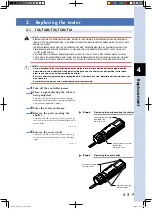
2.5 N15/N15D/N18/N18D
w
WARNING
• BEFORE STARTING THE REPLACEMENT WORK, BE SURE TO DISCONNECT THE ROBOT FROM THE CONTROLLER OR
TURN OFF THE CONTROLLER POWER. IF THE ROBOT OPERATES DURING THE REPLACEMENT WORK, THIS MAY CAUSE
SERIOUS ACCIDENT.
• THE REPLACEMENT WORK WITH THE COvER REMOvED MUST BE PERFORMED ONLY BY PERSONS WHO HAvE THE
REQUIRED QUALIFICATIONS DESCRIBED IN “2. QUALIFICATION OF OPERATORS/WORKERS” IN SECTION 4.1 OF
“SAFETY INSTRUCTIONS”.
• BE CAREFUL NOT TO NEGLECT TIGHTENING SCREWS OR BOLTS. IF ANY COvER IS NOT SECURED FIRMLY, THIS MAY
CAUSE NOISE, COvER DROPPING AND FLYING, HAND ENTANGLEMENT IN DRIvE UNIT DURING TEACHING, OR BURN
DUE TO HAND IN CONTACT WITH HOT SURFACE. SO, BE SURE TO TIGHTEN ALL THE SCREWS AND BOLTS SECURELY.
c
CAUTION
• Be sure to wear safety gloves before starting the work. If you touch any steel material part with bare hands, this
may cause rust.
• Be careful not to drop any screw or bolt during cover removal work.
• Since a positional shift occurs after replacing the motor, return-to-origin must be performed again and the
point data must be re-specified. When removing the parts, note their positional relation and assembly order.
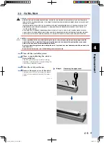
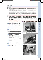
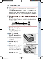
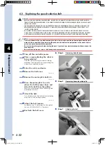
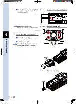
• Provide a space of at least 300mm between each end of the robot and the wall. Do not pull out the ball screw
nut section from the ball screw.
1
Turn off the controller power.
2
Place a sign indicating the robot is
being adjusted.
Place a sign indicating the robot is being
adjusted, to keep others from operating the
controller or operation panel.
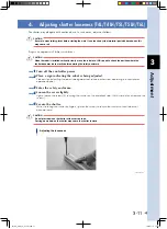
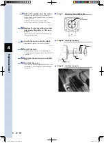
3
Enter the safety enclosure.
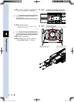
4
Remove the end covers 1 (upper
end covers) from both ends of the
robot.
n
NOTE
For details about how to remove the cover, see
"3. Installing the robot" in Chapter 2 of the
Installation Manual.
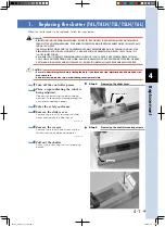
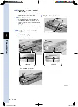
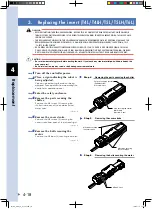
5
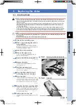
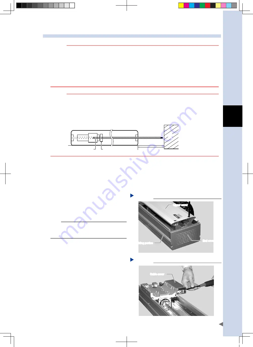
Remove the upper cover.
Remove the screws (4) securing the upper
cover of the robot and remove the upper
cover.
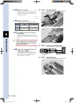
6
Remove the end cover 2 (located at
the lower portion) from both ends.
Remove the screws (2) securing the end
cover of the robot and remove the end
cover 2. For the N15 robot, turn over the
molding portion, remove the screws (2 each
on the left and right), and remove the end
cover 2.
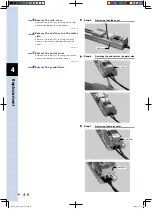
Removing the cover
Step 5-6
Upper cover
Molding portion
End cover 2
53402-AA-00
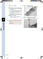
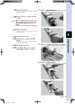
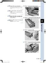
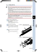
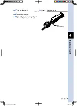
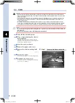
7
Remove the cable cover.
Removing the cable cover
Step 7
Cable cover
53403-AA-00
Allow a space of
300mm or more.
Wall
Ball screw
(Do not pull out.)
Nut section
FLIP-X_maint_E_V1.50.indb 11
18/05/15 15:01
Summary of Contents for FLIP-X Series
Page 2: ...FLIP X_maint_E_V1 50 indb 2 18 05 15 15 00...
Page 40: ...FLIP X_maint_E_V1 50 indb 2 18 05 15 15 01...
Page 41: ...Chapter 1 Overview Contents 1 Overview 1 1 FLIP X_maint_E_V1 50 indb 1 18 05 15 15 01...
Page 42: ...FLIP X_maint_E_V1 50 indb 2 18 05 15 15 01...
Page 44: ...FLIP X_maint_E_V1 50 indb 2 18 05 15 15 01...
Page 46: ...FLIP X_maint_E_V1 50 indb 2 18 05 15 15 01...
Page 60: ...FLIP X_maint_E_V1 50 indb 2 18 05 15 15 01...
Page 72: ...FLIP X_maint_E_V1 50 indb 12 18 05 15 15 01...
Page 74: ...FLIP X_maint_E_V1 50 indb 2 18 05 15 15 01...
Page 104: ...FLIP X_maint_E_V1 50 indb 2 18 05 15 15 01...


