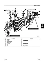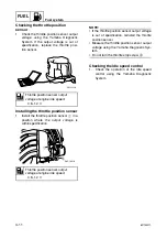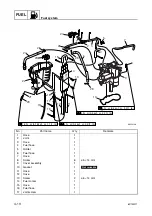
FUEL
Fuel system
4-19
6C13G11
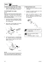
5.
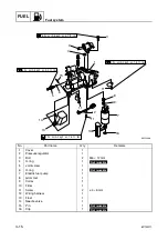
Remove the needle valve and other com-
ponents.
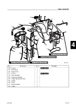
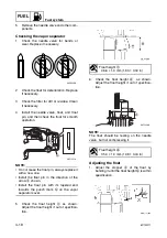
Checking the vapor separator
1.
Check the needle valve for bends or
wear. Replace if necessary.
2.
Check the float for deterioration. Replace
if necessary.
3.
Check the filter for dirt or residue. Clean
if necessary.
4.
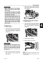
Install the needle valve, float, and float
pin, and then check the float for smooth
operation.
NOTE:
• Do not reuse the float pin, always replace it
with a new one.
• Install the float pin in the direction of the
arrow
a
shown.
• Install the float pin with its tapered end
towards the punch mark
b
on the vapor
separator cover.
5.
Check the float height
c
as shown.
Adjust the float height if out of specifica-
tion.
6.
Check the float height
d
as shown.
Adjust the float height if out of specifica-
tion.
NOTE:
The float should be resting on the needle
valve, but not compressing it.
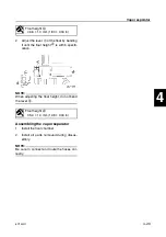
Adjusting the float
1.
Adjust the stopper
a
of the float by
bending it until the float height
b
is within
specification.
S6D54200
S6C14210
a
b
Float height
c
:
46.6
±
1.0 mm (1.83
±
0.04 in)
Float height
d
:
35.0
±
1.0 mm (1.38
±
0.04 in)
S6C14200
d
Summary of Contents for F50F
Page 1: ...F50F FT50G F60C FT60D SERVICE MANUAL 6C1 28197 3G 11 290551 ...
Page 4: ......
Page 48: ...SPEC Specifications 2 25 6C13G11 MEMO ...
Page 190: ...LOWR Lower unit 6 47 6C13G11 Shimming FT50 FT60 6 ...
Page 195: ...6C13G11 6 52 1 2 3 4 5 6 7 8 9 MEMO Backlash FT50 FT60 ...
Page 221: ...6C13G11 7 24 1 2 3 4 5 6 7 8 9 Steering arm ...
Page 249: ...6C13G11 7 52 1 2 3 4 5 6 7 8 9 MEMO Power trim and tilt electrical system ...
Page 272: ...ELEC Electrical systems 8 21 6C13G11 MEMO ...
Page 301: ...6C13G11 i 5 1 2 3 4 5 6 7 8 9 Index MEMO ...
Page 303: ......
Page 304: ...YAMAHA MOTOR CO LTD Printed in the Netherlands Jul 2004 1 2 1 CR E_2 ...

