6C13G11
6-42
1
2
3
4
5
6
7
8
9
2.
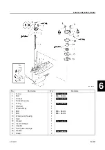
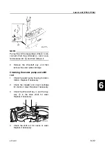
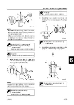
Install the new needle bearing into the
forward gear to the specified depth.
Assembling the drive shaft
1.
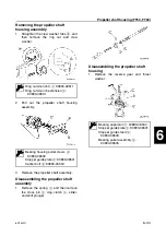
Install a new drive shaft bearing into the
drive shaft using a press.
Installing the pinion
1.
Install the forward gear, then the drive
shaft assembly, pinion, and pinion nut,
and then tighten the nut to the specified
torque.
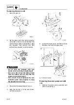
Installing the propeller shaft housing
1.
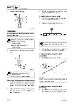
Install the washer
1
and propeller shaft
assembly
2
into the propeller shaft
housing assembly
3
.
2.
Apply grease to a new O-ring.
Needle bearing attachment
1
:
90890-06607
Needle bearing attachment
2
:
90890-06614
Driver rod L3
3
: 90890-06652
Depth
a
:
0.95–1.45 mm (0.04–0.06 in)
Bearing inner race attachment
1
:
90890-06643
Drive shaft holder 4
1
: 90890-06518
Pinion nut holder
2
:
New: 90890-06715
Current: 90890-06505
T
R
.
.
Pinion nut:
93 N·m (9.3 kgf·m, 68.6 ft·lb)
S68S6400
1
2
Summary of Contents for F50F
Page 1: ...F50F FT50G F60C FT60D SERVICE MANUAL 6C1 28197 3G 11 290551 ...
Page 4: ......
Page 48: ...SPEC Specifications 2 25 6C13G11 MEMO ...
Page 190: ...LOWR Lower unit 6 47 6C13G11 Shimming FT50 FT60 6 ...
Page 195: ...6C13G11 6 52 1 2 3 4 5 6 7 8 9 MEMO Backlash FT50 FT60 ...
Page 221: ...6C13G11 7 24 1 2 3 4 5 6 7 8 9 Steering arm ...
Page 249: ...6C13G11 7 52 1 2 3 4 5 6 7 8 9 MEMO Power trim and tilt electrical system ...
Page 272: ...ELEC Electrical systems 8 21 6C13G11 MEMO ...
Page 301: ...6C13G11 i 5 1 2 3 4 5 6 7 8 9 Index MEMO ...
Page 303: ......
Page 304: ...YAMAHA MOTOR CO LTD Printed in the Netherlands Jul 2004 1 2 1 CR E_2 ...

